
Hardware Maintenance Manual
Page 9
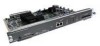
...Figure 2-24 Figure 2-25 Figure 2-26 Figure 2-27 Figure 2-28 Figure 2-29 Figure 2-30 Figure 2-31 Figure 2-32 Cisco 4000 Series Chassis-Front Panel 1-2 Cisco 4000 Series Memory Systems and Software Images 1-4 Installation Checklist 2-5 Router-Rear View Showing Slot Numbering and Interface Ports 2-7 Router-...FDDI Network Interface Connector, MIC Type 2-26 Dual-Attachment Multimode FDDI Module-End View 2-27 Dual-Attachment FDDI Optical Bypass Switch and PHY Connections 2-27 Single-Attachment Multimode FDDI Module-End View 2-28 4-Port BRI Network Processor Module 2-29 8-Port BRI Network Processor ...
...Figure 2-24 Figure 2-25 Figure 2-26 Figure 2-27 Figure 2-28 Figure 2-29 Figure 2-30 Figure 2-31 Figure 2-32 Cisco 4000 Series Chassis-Front Panel 1-2 Cisco 4000 Series Memory Systems and Software Images 1-4 Installation Checklist 2-5 Router-Rear View Showing Slot Numbering and Interface Ports 2-7 Router-...FDDI Network Interface Connector, MIC Type 2-26 Dual-Attachment Multimode FDDI Module-End View 2-27 Dual-Attachment FDDI Optical Bypass Switch and PHY Connections 2-27 Single-Attachment Multimode FDDI Module-End View 2-28 4-Port BRI Network Processor Module 2-29 8-Port BRI Network Processor ...
Hardware Maintenance Manual
Page 47
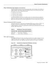
...Figure 2-24) use simplex FC-type connectors (see Figure 2-25). If the distance between two connected stations is the SAS and contains the PHY-A port. The ports accept standard 8.7 to 10/125-micron single-mode fiber-optic cable, supporting connections at distances up to 1.2 miles .... Figure 2-24 Dual-Attachment Single-Mode FDDI Module-End View PHY-B XMTR PHY-A RCVR FDDI WARNING PHY-B RING OP PHY-A RING OP AVOID EXPOSURE-INVISIBLE LASER RADIATION IS EMITTED FROM THESE APERTURES. 1300 NM CLASS 1 LASER PRODUCT LASERKLASSE 1 CISCO SYSTEMS, INC. 170 WEST TASMAN DRIVE SAN JOSE, CA 95134...
...Figure 2-24) use simplex FC-type connectors (see Figure 2-25). If the distance between two connected stations is the SAS and contains the PHY-A port. The ports accept standard 8.7 to 10/125-micron single-mode fiber-optic cable, supporting connections at distances up to 1.2 miles .... Figure 2-24 Dual-Attachment Single-Mode FDDI Module-End View PHY-B XMTR PHY-A RCVR FDDI WARNING PHY-B RING OP PHY-A RING OP AVOID EXPOSURE-INVISIBLE LASER RADIATION IS EMITTED FROM THESE APERTURES. 1300 NM CLASS 1 LASER PRODUCT LASERKLASSE 1 CISCO SYSTEMS, INC. 170 WEST TASMAN DRIVE SAN JOSE, CA 95134...
Hardware Maintenance Manual
Page 48
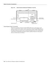
...) for network and chassis connections in multimode FDDI applications. The PHY-A port is the bottom port (see Figure 2-24 and Figure 2-27), and PHY-B is the top port on the other DAS and PHY-B on the module to PHY-B on the other DAS. 2-26 Cisco 4000 Series Hardware Installation and Maintenance H1349a Avoid exposure and...
...) for network and chassis connections in multimode FDDI applications. The PHY-A port is the bottom port (see Figure 2-24 and Figure 2-27), and PHY-B is the top port on the other DAS and PHY-B on the module to PHY-B on the other DAS. 2-26 Cisco 4000 Series Hardware Installation and Maintenance H1349a Avoid exposure and...
Hardware Maintenance Manual
Page 49
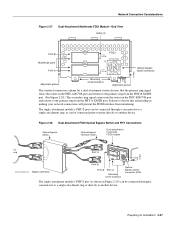
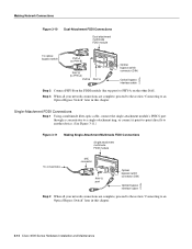
... Optical bypass switch Optical bypass interface cable Dual-attachment multimode FDDI module To ring PHY-A PHY-B PHY-A RING OP FDDI OPT-BYPASS RING OP H1405a Bypass operation PHY-B PHY-B PHY-A Mounting screw locations Optical bypass switch connector (DIN) The single-attachment module's PHY-S port (as shown in making your network connections will prevent the FDDI interface from...
... Optical bypass switch Optical bypass interface cable Dual-attachment multimode FDDI module To ring PHY-A PHY-B PHY-A RING OP FDDI OPT-BYPASS RING OP H1405a Bypass operation PHY-B PHY-B PHY-A Mounting screw locations Optical bypass switch connector (DIN) The single-attachment module's PHY-S port (as shown in making your network connections will prevent the FDDI interface from...
Hardware Maintenance Manual
Page 50
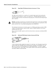
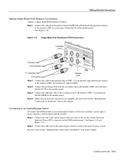
... is enabled, and the ring will be unaffected. Network Connection Considerations Figure 2-29 Single-Attachment Multimode FDDI Module-End View LED PHY-S Multimode port Alignment groove PHY-S FDDI OPT-BYPASS PHY-S RING OPT Optical bypass switch connector H1401a Mounting screw locations Alignment groove Optical Bypass Switch Connections Both the dual-attachment and single... optical bypass switch is lost , the optical bypass switch is detected or if the operator chooses to take the router out of the ring. 2-28 Cisco 4000 Series Hardware Installation and Maintenance
... is enabled, and the ring will be unaffected. Network Connection Considerations Figure 2-29 Single-Attachment Multimode FDDI Module-End View LED PHY-S Multimode port Alignment groove PHY-S FDDI OPT-BYPASS PHY-S RING OPT Optical bypass switch connector H1401a Mounting screw locations Alignment groove Optical Bypass Switch Connections Both the dual-attachment and single... optical bypass switch is lost , the optical bypass switch is detected or if the operator chooses to take the router out of the ring. 2-28 Cisco 4000 Series Hardware Installation and Maintenance
Hardware Maintenance Manual
Page 69
... by the apparatus, together with these procedures to PHY-B on the FDDI module (the bottom port) to make Fiber Distributed Data Interface (FDDI) connections. Failure to safely install the Cisco Systems BRI module correctly within the rating of the... apparatus are also SELV circuits. (SELV circuits are as follows: • +5 VDC/2.5 mA • +12 VDC/100 mA • -12 VDC/100 mA Ensure that the power drawn by any auxiliary apparatus, lies within a host chassis, seek advice from a qualified telecommunications engineer...
... by the apparatus, together with these procedures to PHY-B on the FDDI module (the bottom port) to make Fiber Distributed Data Interface (FDDI) connections. Failure to safely install the Cisco Systems BRI module correctly within the rating of the... apparatus are also SELV circuits. (SELV circuits are as follows: • +5 VDC/2.5 mA • +12 VDC/100 mA • -12 VDC/100 mA Ensure that the power drawn by any auxiliary apparatus, lies within a host chassis, seek advice from a qualified telecommunications engineer...
Hardware Maintenance Manual
Page 70
..., proceed to the section "Connecting to an Optical Bypass Switch" later in this chapter. 3-12 Cisco 4000 Series Hardware Installation and Maintenance Single-Attachment FDDI Connections Step 1 Using a multimode fiber-optic cable, connect the single-attachment module's PHY-S port through a concentrator to a single-attachment ring, or connect it point-to-point directly...
..., proceed to the section "Connecting to an Optical Bypass Switch" later in this chapter. 3-12 Cisco 4000 Series Hardware Installation and Maintenance Single-Attachment FDDI Connections Step 1 Using a multimode fiber-optic cable, connect the single-attachment module's PHY-S port through a concentrator to a single-attachment ring, or connect it point-to-point directly...
Hardware Maintenance Manual
Page 71
...Final Connections to the Router" later in this chapter. A at the primary ring upstream station) to the module's PHY-A receive port, labeled RCVR on the module panel. A transmit port labeled XMTR on the FDDI module panel. (...12.) Figure 3-12 Single-Mode Dual-Attachment FDDI Connections To primary ring From secondary ring Transmitter ports PHY-B XMTR PHY-A RCVR FDDI PRHINYG-BOP PRHINYG-AOP WARNING C1SD7AAIS0TNCEWJO: OESSALFSARYVTESOOS,TEMITCDRACEATESLRMHAXMA9SEPSLDS5SAAO,I11SEANSIE3TNAURL4IDPOKARC-LSER1EN.AER7-SIRIVI0TSSNEPUE6VERR1IMOSEDIISTBUT.CLETED S"PCueobrfmcohrpmalipeatsnecwr ...
...Final Connections to the Router" later in this chapter. A at the primary ring upstream station) to the module's PHY-A receive port, labeled RCVR on the module panel. A transmit port labeled XMTR on the FDDI module panel. (...12.) Figure 3-12 Single-Mode Dual-Attachment FDDI Connections To primary ring From secondary ring Transmitter ports PHY-B XMTR PHY-A RCVR FDDI PRHINYG-BOP PRHINYG-AOP WARNING C1SD7AAIS0TNCEWJO: OESSALFSARYVTESOOS,TEMITCDRACEATESLRMHAXMA9SEPSLDS5SAAO,I11SEANSIE3TNAURL4IDPOKARC-LSER1EN.AER7-SIRIVI0TSSNEPUE6VERR1IMOSEDIISTBUT.CLETED S"PCueobrfmcohrpmalipeatsnecwr ...
Hardware Maintenance Manual
Page 89
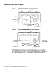
.... (See Figure 4-12.) Figure 4-10 Dual-Attachment Single-Mode FDDI Module-End View PHY-B XMTR PHY-A RCVR FDDI WARNING PHY-B RING OP PHY-A RING OP AVOID EXPOSURE-INVISIBLE LASER RADIATION IS EMITTED FROM THESE APERTURES. 1300 NM CLASS 1 LASER PRODUCT LASERKLASSE 1 CISCO SYSTEMS, INC. 170 WEST TASMAN DRIVE SAN JOSE, CA 95134-1706 DATE: "Complies...
.... (See Figure 4-12.) Figure 4-10 Dual-Attachment Single-Mode FDDI Module-End View PHY-B XMTR PHY-A RCVR FDDI WARNING PHY-B RING OP PHY-A RING OP AVOID EXPOSURE-INVISIBLE LASER RADIATION IS EMITTED FROM THESE APERTURES. 1300 NM CLASS 1 LASER PRODUCT LASERKLASSE 1 CISCO SYSTEMS, INC. 170 WEST TASMAN DRIVE SAN JOSE, CA 95134-1706 DATE: "Complies...
Hardware Maintenance Manual
Page 90
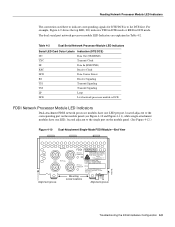
...not actively inserted into the ring, the LED is inserted into a ring. 4-10 Cisco 4000 Series Hardware Installation and Maintenance Dual-attachment FDDI module LEDs indicate which PHY on the network processor module is not lit. when the LED is not lit, it...Reading Network Processor Module LED Indicators Figure 4-11 Dual-Attachment Multimode FDDI Module-End View LEDs (2) PHY-B Multimode ports PHY-A Alignment groove PHY-B PHY-A PHY-B RING OP FDDI OPT-BYPASS PHY-A RING OP Optical bypass switch connector H1400a Mounting screw locations Alignment groove Figure 4-12 Single-Attachment...
...not actively inserted into the ring, the LED is inserted into a ring. 4-10 Cisco 4000 Series Hardware Installation and Maintenance Dual-attachment FDDI module LEDs indicate which PHY on the network processor module is not lit. when the LED is not lit, it...Reading Network Processor Module LED Indicators Figure 4-11 Dual-Attachment Multimode FDDI Module-End View LEDs (2) PHY-B Multimode ports PHY-A Alignment groove PHY-B PHY-A PHY-B RING OP FDDI OPT-BYPASS PHY-A RING OP Optical bypass switch connector H1400a Mounting screw locations Alignment groove Figure 4-12 Single-Attachment...