
Hardware Maintenance Manual
Page 9
... Cisco 4000 Series Memory Systems and Software Images 1-4 Installation Checklist 2-5 Router-Rear View Showing Slot Numbering and Interface Ports 2-7 Router-Rear View Showing Serial Port Unit Numbering 2-8 Slot Filler Panel 2-9 Ethernet Network Processor Module with AUI and 10BaseT Connectors 2-11 Single-Port Ethernet... FDDI Network Interface Connector, MIC Type 2-26 Dual-Attachment Multimode FDDI Module-End View 2-27 Dual-Attachment FDDI Optical Bypass Switch and PHY Connections 2-27 Single-Attachment Multimode FDDI Module-End View 2-28 4-Port BRI Network Processor Module 2-29 8-Port BRI...
... Cisco 4000 Series Memory Systems and Software Images 1-4 Installation Checklist 2-5 Router-Rear View Showing Slot Numbering and Interface Ports 2-7 Router-Rear View Showing Serial Port Unit Numbering 2-8 Slot Filler Panel 2-9 Ethernet Network Processor Module with AUI and 10BaseT Connectors 2-11 Single-Port Ethernet... FDDI Network Interface Connector, MIC Type 2-26 Dual-Attachment Multimode FDDI Module-End View 2-27 Dual-Attachment FDDI Optical Bypass Switch and PHY Connections 2-27 Single-Attachment Multimode FDDI Module-End View 2-28 4-Port BRI Network Processor Module 2-29 8-Port BRI...

Hardware Maintenance Manual
Page 28
..., Number 1 and Number 2 Phillips • One serial port adapter cable for multimode Fiber Distributed Data Interface (FDDI) connections. 2-6 Cisco 4000 Series Hardware Installation and Maintenance Each time a procedure is completed. • Upgrades and removal or replacement procedures-Use the Site Log...most provide either a V.35, EIA/TIA-449, or EIA-530 electrical interface. • Ethernet transceiver. • Token Ring media attachment unit (MAU). • Optical bypass switch or concentrator for each serial port to connect each procedure is performed on the router, update...
..., Number 1 and Number 2 Phillips • One serial port adapter cable for multimode Fiber Distributed Data Interface (FDDI) connections. 2-6 Cisco 4000 Series Hardware Installation and Maintenance Each time a procedure is completed. • Upgrades and removal or replacement procedures-Use the Site Log...most provide either a V.35, EIA/TIA-449, or EIA-530 electrical interface. • Ethernet transceiver. • Token Ring media attachment unit (MAU). • Optical bypass switch or concentrator for each serial port to connect each procedure is performed on the router, update...

Hardware Maintenance Manual
Page 29
... Slot 3 Token Ring port 10BaseT Chassis Serial interface ports port release screw Slot 1 Ethernet port Slot 2 Dual serial module H1033a Token Ring module Ethernet module Auxiliary port Console port Power On/off switch Slot Numbering The chassis contains slots for the modules in Figure 2-2 are as listed ...viewed from the rear, the power cable and power switch appear on the right side of the same type. Any module can be moved to any other available slot location. Table 2-1 Slot No. 1 2 3 Unit Numbering for Dual Serial, Ethernet, and Token Ring Modules Interface Type Serial Port ...
... Slot 3 Token Ring port 10BaseT Chassis Serial interface ports port release screw Slot 1 Ethernet port Slot 2 Dual serial module H1033a Token Ring module Ethernet module Auxiliary port Console port Power On/off switch Slot Numbering The chassis contains slots for the modules in Figure 2-2 are as listed ...viewed from the rear, the power cable and power switch appear on the right side of the same type. Any module can be moved to any other available slot location. Table 2-1 Slot No. 1 2 3 Unit Numbering for Dual Serial, Ethernet, and Token Ring Modules Interface Type Serial Port ...
Hardware Maintenance Manual
Page 30
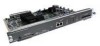
...a slot filler panel. INPUT 100-240VAC 50/60HZ 3.0-1.5 AMPS Power On/off switch Table 2-3 Slot No. 1 2 3 Unit Numbering Addresses for Dual Serial and Two Ethernet Modules Interface Type Serial Port (Top) Serial Port (Bottom) Ethernet Ethernet Unit Address No. 1 0 0 1 Figure 2-3 shows a chassis configured with ... to Make Connections If the Token Ring module in Figure 2-2 was replaced by a second Ethernet module, the unit addresses would be as listed in Table 2-2. H1402 a 2-8 Cisco 4000 Series Hardware Installation and Maintenance Table 2-2 Slot No. 1 2 3 Unit Numbering Addresses...
...a slot filler panel. INPUT 100-240VAC 50/60HZ 3.0-1.5 AMPS Power On/off switch Table 2-3 Slot No. 1 2 3 Unit Numbering Addresses for Dual Serial and Two Ethernet Modules Interface Type Serial Port (Top) Serial Port (Bottom) Ethernet Ethernet Unit Address No. 1 0 0 1 Figure 2-3 shows a chassis configured with ... to Make Connections If the Token Ring module in Figure 2-2 was replaced by a second Ethernet module, the unit addresses would be as listed in Table 2-2. H1402 a 2-8 Cisco 4000 Series Hardware Installation and Maintenance Table 2-2 Slot No. 1 2 3 Unit Numbering Addresses...
Hardware Maintenance Manual
Page 85
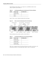
...the line. • TX (transmit)-When lit, this indicates the autopolarity reading detected the polarity was defective and corrected for it (switched it indicates a ring speed of 16 Mbps; Reading Network Processor Module LED Indicators • POL (polarity)-When lit, this indicates the... system is sending Ethernet transmissions. when not lit, it ). • LNK (link)-When lit, this indicates 10BaseT is selected, and the link is available. &#...
...the line. • TX (transmit)-When lit, this indicates the autopolarity reading detected the polarity was defective and corrected for it (switched it indicates a ring speed of 16 Mbps; Reading Network Processor Module LED Indicators • POL (polarity)-When lit, this indicates the... system is sending Ethernet transmissions. when not lit, it ). • LNK (link)-When lit, this indicates 10BaseT is selected, and the link is available. &#...
Hardware Maintenance Manual
Page 138
...type 2-10, 4-4 meminfo D-4 o (display virtual configuration register) C-3 o/r (reset) C-3 reload B-2 reset D-3 ROM monitor diagnostics Cisco 4000-M C-1 Cisco 4500-M D-1 Cisco 4700 D-1 setup 3-22 show version B-2 stack D-4 sysret D-4 t (test) C-3 terminal padding 3-2 component tray layout 5-5 config...Cisco 4500-M D-4 Cisco 4700 D-4 displaying settings C-3 resetting C-3 confreg command D-4 connections 10BaseT 2-10 9-pin D-type 3-2 auxiliary port 2-9 considerations when making 2-10 console port 2-9 Ethernet attaching to network 3-3 port, considerations 2-12 final 3-22 NT1 3-6 optical bypass switch...
...type 2-10, 4-4 meminfo D-4 o (display virtual configuration register) C-3 o/r (reset) C-3 reload B-2 reset D-3 ROM monitor diagnostics Cisco 4000-M C-1 Cisco 4500-M D-1 Cisco 4700 D-1 setup 3-22 show version B-2 stack D-4 sysret D-4 t (test) C-3 terminal padding 3-2 component tray layout 5-5 config...Cisco 4500-M D-4 Cisco 4700 D-4 displaying settings C-3 resetting C-3 confreg command D-4 connections 10BaseT 2-10 9-pin D-type 3-2 auxiliary port 2-9 considerations when making 2-10 console port 2-9 Ethernet attaching to network 3-3 port, considerations 2-12 final 3-22 NT1 3-6 optical bypass switch...
Hardware Maintenance Manual
Page 140
... software from Flash B-6 log, site 2-6 M maintenance, system 5-1 making connections auxiliary port 2-9 console port 3-1 Ethernet 2-10, 3-3 FDDI 2-25, 3-11 final 3-22 network 3-2 optical bypass switch 2-28, 3-13 serial 2-19, 3-4, 3-5 Token Ring 2-14, 3-2 media-type command 2-10, 4-4 meminfo command D-4 memory adding shared-memory SIMMs 5-13 system-memory SIMMs 5-8 6 Cisco 4000 Series Hardware Installation and Maintenance
... software from Flash B-6 log, site 2-6 M maintenance, system 5-1 making connections auxiliary port 2-9 console port 3-1 Ethernet 2-10, 3-3 FDDI 2-25, 3-11 final 3-22 network 3-2 optical bypass switch 2-28, 3-13 serial 2-19, 3-4, 3-5 Token Ring 2-14, 3-2 media-type command 2-10, 4-4 meminfo command D-4 memory adding shared-memory SIMMs 5-13 system-memory SIMMs 5-8 6 Cisco 4000 Series Hardware Installation and Maintenance

Hardware Maintenance Manual
Page 141
... C-2 preventing C-2 network activity indicator 4-4 connection considerations network processor module ATM 2-34 network processor modules dual serial 2-20 Ethernet 2-10 FDDI 2-27, 4-10 LED indicators 4-4 locations 5-6 removing 5-4 replacing 5-20 Token Ring 2-13 nonreturn to zero...) C-3 o/r command (reset) C-3 opening the chassis 5-1 operating conditions European Community F-1 temperature 1-3 operating conditions United Kingdom E-1 optical bypass switch connecting to 3-13 uses 2-28 ordering publications xv overview, series 1-1 P packing list 2-36 pinouts auxiliary port A-2 BRI 3-8, A-22 ...
... C-2 preventing C-2 network activity indicator 4-4 connection considerations network processor module ATM 2-34 network processor modules dual serial 2-20 Ethernet 2-10 FDDI 2-27, 4-10 LED indicators 4-4 locations 5-6 removing 5-4 replacing 5-20 Token Ring 2-13 nonreturn to zero...) C-3 o/r command (reset) C-3 opening the chassis 5-1 operating conditions European Community F-1 temperature 1-3 operating conditions United Kingdom E-1 optical bypass switch connecting to 3-13 uses 2-28 ordering publications xv overview, series 1-1 P packing list 2-36 pinouts auxiliary port A-2 BRI 3-8, A-22 ...
