Hardware Installation Guide
Page 5
... Quotient, TransPath, and VCO are registered trademarks of Cisco Systems, Inc.; CCIP, CCSP, the Cisco Arrow logo, the Cisco Powered Network mark, Cisco Unity, Follow Me Browsing, FormShare, and StackWise are trademarks of the word partner does not imply a partnership relationship between Cisco and any other company. (0304R) Catalyst 3750 Switch Hardware Installation Guide Copyright © 2003...
... Quotient, TransPath, and VCO are registered trademarks of Cisco Systems, Inc.; CCIP, CCSP, the Cisco Arrow logo, the Cisco Powered Network mark, Cisco Unity, Follow Me Browsing, FormShare, and StackWise are trademarks of the word partner does not imply a partnership relationship between Cisco and any other company. (0304R) Catalyst 3750 Switch Hardware Installation Guide Copyright © 2003...
Hardware Installation Guide
Page 7
... Obtaining Technical Assistance xxv Cisco.com xxvi Technical Assistance Center xxvi Cisco TAC Website xxvii Cisco TAC Escalation Center xxvii Obtaining Additional Publications and Information xxviii Using Express Setup 1-1 Taking Out What You Need 1-2 Powering On the Switch 1-3 Starting Express Setup 1-4 Configuring the Switch Settings 1-9 Verifying Switch IP Address (Optional) 1-10 Catalyst 3750 Switch Hardware...
... Obtaining Technical Assistance xxv Cisco.com xxvi Technical Assistance Center xxvi Cisco TAC Website xxvii Cisco TAC Escalation Center xxvii Obtaining Additional Publications and Information xxviii Using Express Setup 1-1 Taking Out What You Need 1-2 Powering On the Switch 1-3 Starting Express Setup 1-4 Configuring the Switch Settings 1-9 Verifying Switch IP Address (Optional) 1-10 Catalyst 3750 Switch Hardware...

Hardware Installation Guide
Page 8
... Slots 2-7 SFP Modules 2-7 LEDs 2-8 System LED 2-9 RPS LED 2-9 Master LED 2-10 Port LEDs and Modes 2-10 Rear Panel Description 2-14 StackWise Ports 2-15 Power Connectors 2-16 Internal Power Supply Connector 2-16 Cisco RPS Connector 2-16 Console Port 2-17 Management Options 2-18 Network Configurations 2-19 Switch Installation 3-1 Preparing for Installation 3-1 Warnings 3-2 EMC Regulatory Statements...
... Slots 2-7 SFP Modules 2-7 LEDs 2-8 System LED 2-9 RPS LED 2-9 Master LED 2-10 Port LEDs and Modes 2-10 Rear Panel Description 2-14 StackWise Ports 2-15 Power Connectors 2-16 Internal Power Supply Connector 2-16 Cisco RPS Connector 2-16 Console Port 2-17 Management Options 2-18 Network Configurations 2-19 Switch Installation 3-1 Preparing for Installation 3-1 Warnings 3-2 EMC Regulatory Statements...

Hardware Installation Guide
Page 9
... 3-11 Planning the Stack 3-12 Planning Considerations 3-12 Powering Considerations 3-13 Cabling Considerations 3-14 Recommended Cabling Configurations 3-15 Installing the Switch 3-17 Rack Mounting 3-18 Removing Screws from the Switch 3-19 Attaching Brackets to the Catalyst 3750G-24TS Switch 3-20 Attaching Brackets to the Catalyst 3750-24TS, 3750G-24T, 3750G-12S, and 3750...
... 3-11 Planning the Stack 3-12 Planning Considerations 3-12 Powering Considerations 3-13 Cabling Considerations 3-14 Recommended Cabling Configurations 3-15 Installing the Switch 3-17 Rack Mounting 3-18 Removing Screws from the Switch 3-19 Attaching Brackets to the Catalyst 3750G-24TS Switch 3-20 Attaching Brackets to the Catalyst 3750-24TS, 3750G-24T, 3750G-12S, and 3750...

Hardware Installation Guide
Page 11
... Through the Console Port D-3 Taking Out What You Need D-4 Stacking the Switches (Optional) D-5 Connecting to the Console Port D-7 Starting the Terminal Emulation Software D-9 Connecting to a Power Source D-9 Entering the Initial Configuration Information D-10 IP Settings D-10 Completing the Setup Program D-11 78-15136-02...
... Through the Console Port D-3 Taking Out What You Need D-4 Stacking the Switches (Optional) D-5 Connecting to the Console Port D-7 Starting the Terminal Emulation Software D-9 Connecting to a Power Source D-9 Entering the Initial Configuration Information D-10 IP Settings D-10 Completing the Setup Program D-11 78-15136-02...

Hardware Installation Guide
Page 12
Contents E A P P E N D I X INDEX Translated Safety Warnings E-1 Attaching the Cisco RPS (model PWR300-AC-RPS-N1) E-1 Attaching the Cisco RPS (model PWR675-AC-RPS-N1) E-2 Installation Warning E-4 Installation Instructions E-5 Jewelry Removal Warning E-6 Stacking the Chassis Warning...Overtemperature Warning E-14 Working During Lightning Activity E-16 Product Disposal Warning E-17 Chassis Warning for Rack-Mounting and Servicing E-19 Redundant Power Supply Connection Warning E-24 Switch Installation Warning E-25 Restricted Area E-27 Ethernet Cable Shielding in Offices E-28 Laser Beam Exposure E-30...
Contents E A P P E N D I X INDEX Translated Safety Warnings E-1 Attaching the Cisco RPS (model PWR300-AC-RPS-N1) E-1 Attaching the Cisco RPS (model PWR675-AC-RPS-N1) E-2 Installation Warning E-4 Installation Instructions E-5 Jewelry Removal Warning E-6 Stacking the Chassis Warning...Overtemperature Warning E-14 Working During Lightning Activity E-16 Product Disposal Warning E-17 Chassis Warning for Rack-Mounting and Servicing E-19 Redundant Power Supply Connection Warning E-24 Switch Installation Warning E-25 Restricted Area E-27 Ethernet Cable Shielding in Offices E-28 Laser Beam Exposure E-30...

Hardware Installation Guide
Page 14
...Hardware Warranty A Cisco product hardware warranty is supported for assistance: http://www.cisco.com/public/Support_root.shtml. Enter this part number in Adobe Portable Document Format (PDF). Read the document online, or click the PDF icon to view the document. Catalyst 3750 Switch ...on the customer location. Replacement, Repair, or Refund Policy for Hardware Cisco or its service center will use the product, provided that the fan and power supply warranty is limited to five (5) years. Cisco Limited Lifetime Hardware Warranty Terms 3. Actual delivery times can also contact ...
...Hardware Warranty A Cisco product hardware warranty is supported for assistance: http://www.cisco.com/public/Support_root.shtml. Enter this part number in Adobe Portable Document Format (PDF). Read the document online, or click the PDF icon to view the document. Catalyst 3750 Switch ...on the customer location. Replacement, Repair, or Refund Policy for Hardware Cisco or its service center will use the product, provided that the fan and power supply warranty is limited to five (5) years. Cisco Limited Lifetime Hardware Warranty Terms 3. Actual delivery times can also contact ...
Hardware Installation Guide
Page 29
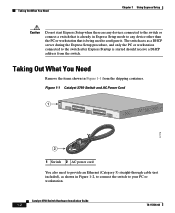
The setup procedure includes these steps: • Taking Out What You Need, page 1-2 • Powering On the Switch, page 1-3 • Starting Express Setup, page 1-4 • Configuring the Switch Settings, page 1-9 • Where to determine the release. For quick ...Program." Note Express Setup is supported on the rear panel of the switch to Go Next, page 1-12 78-15136-02 Catalyst 3750 Switch Hardware Installation Guide 1-1 CH A P T E R 1 Using Express Setup This chapter provides a quick, step-by-step setup procedure for switches running Cisco IOS Release 12.1(14)EA1 or later.
The setup procedure includes these steps: • Taking Out What You Need, page 1-2 • Powering On the Switch, page 1-3 • Starting Express Setup, page 1-4 • Configuring the Switch Settings, page 1-9 • Where to determine the release. For quick ...Program." Note Express Setup is supported on the rear panel of the switch to Go Next, page 1-12 78-15136-02 Catalyst 3750 Switch Hardware Installation Guide 1-1 CH A P T E R 1 Using Express Setup This chapter provides a quick, step-by-step setup procedure for switches running Cisco IOS Release 12.1(14)EA1 or later.
Hardware Installation Guide
Page 30
... 1 SYST RPS MASTR STAT 1X DUPLX SPEED STACK MODE 2X 11X 13X 12X 14X 23X Catalyst 3750 SERIES 24X 97175 2 1 Switch 2 AC power cord You also need to provide an Ethernet (Category 5) straight-through cable (not included), as a DHCP server during the Express Setup procedure, and only the ...
... 1 SYST RPS MASTR STAT 1X DUPLX SPEED STACK MODE 2X 11X 13X 12X 14X 23X Catalyst 3750 SERIES 24X 97175 2 1 Switch 2 AC power cord You also need to provide an Ethernet (Category 5) straight-through cable (not included), as a DHCP server during the Express Setup procedure, and only the ...

Hardware Installation Guide
Page 31
Figure 1-3 Connecting the Power 1 STACK 1 STACK 2 CONSOLE 1.2A-100R>06A-A2T4,IN05GV0-~60 HZ DSCPIENPCPO+IUWF1T2IEESvDRFISO@NUR1MP3RPAAELNYMUOATLE 97176 1 Switch 2 2 AC power cord 78-15136-02 Catalyst 3750 Switch Hardware Installation Guide 1-3 Chapter 1 Using Express Setup Figure 1-2 Ethernet Cable Powering On the Switch 89887 Powering On the Switch Complete these steps to power on the switch: Step 1 Connect one end of the AC power cord to the power connector on the switch rear panel, as shown in Figure 1-3.
Figure 1-3 Connecting the Power 1 STACK 1 STACK 2 CONSOLE 1.2A-100R>06A-A2T4,IN05GV0-~60 HZ DSCPIENPCPO+IUWF1T2IEESvDRFISO@NUR1MP3RPAAELNYMUOATLE 97176 1 Switch 2 2 AC power cord 78-15136-02 Catalyst 3750 Switch Hardware Installation Guide 1-3 Chapter 1 Using Express Setup Figure 1-2 Ethernet Cable Powering On the Switch 89887 Powering On the Switch Complete these steps to power on the switch: Step 1 Connect one end of the AC power cord to the power connector on the switch rear panel, as shown in Figure 1-3.

Hardware Installation Guide
Page 32
... create a username with Express Setup. For information about troubleshooting a POST failure, see Chapter 4, "Troubleshooting," to determine a course of the power cable to ensure that the switch can use the Cluster Managment Suite (CMS) or the command-line interface (CLI). The switch acts as ... the PC or workstation connected to configure a switch. The MASTR LED is complete, only the SYST and STAT LEDs remain green. Catalyst 3750 Switch Hardware Installation Guide 1-4 78-15136-02 POST lasts approximately 1 minute. Starting Express Setup Express Setup is a browser-based program...
... create a username with Express Setup. For information about troubleshooting a POST failure, see Chapter 4, "Troubleshooting," to determine a course of the power cable to ensure that the switch can use the Cluster Managment Suite (CMS) or the command-line interface (CLI). The switch acts as ... the PC or workstation connected to configure a switch. The MASTR LED is complete, only the SYST and STAT LEDs remain green. Catalyst 3750 Switch Hardware Installation Guide 1-4 78-15136-02 POST lasts approximately 1 minute. Starting Express Setup Express Setup is a browser-based program...

Hardware Installation Guide
Page 42
..., autonegotiates the speed and supports only full-duplex mode • The Catalyst 3750 switches support stacking. Connection for optional Cisco RPS 300 redundant power system that operates on AC input and supplies backup DC power output to nine switches in half-duplex mode at 10 or 100 Mbps... either operate at 10, 100, or 1000 Mbps in full-duplex mode or in a stack by cabling the StackWise ports. Catalyst 3750 Switch Hardware Installation Guide 2-2 78-15136-02 Catalyst 3750-48TS-48 10/100 Ethernet ports and 4 SFP module slots - These are hot-swappable • Power redundancy -
..., autonegotiates the speed and supports only full-duplex mode • The Catalyst 3750 switches support stacking. Connection for optional Cisco RPS 300 redundant power system that operates on AC input and supplies backup DC power output to nine switches in half-duplex mode at 10 or 100 Mbps... either operate at 10, 100, or 1000 Mbps in full-duplex mode or in a stack by cabling the StackWise ports. Catalyst 3750 Switch Hardware Installation Guide 2-2 78-15136-02 Catalyst 3750-48TS-48 10/100 Ethernet ports and 4 SFP module slots - These are hot-swappable • Power redundancy -

Hardware Installation Guide
Page 43
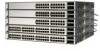
.../100 ports are grouped in Figure 2-2 and Figure 2-3. Connection for optional Cisco RPS 675 redundant power system that operates on AC input and supplies backup DC power output to 28. 78-15136-02 Catalyst 3750 Switch Hardware Installation Guide 2-3 Figure 2-1 Catalyst 3750-24TS Front Panel 86541 SYST RPS MASTR STAT DUPLX SPEED STACK MODE... 34 56 78 9 10 11 12 11X 2X 12X 13 14 13X 15 16 17 18 19 20 21 22 23 24 23X 14X 24X Catalyst 3750 SERIES 1 2 1 2 1 10/100 ports 2 SFP module ports The 10/100/1000 ports on the far left, as shown in pairs. Chapter 2 Product ...
.../100 ports are grouped in Figure 2-2 and Figure 2-3. Connection for optional Cisco RPS 675 redundant power system that operates on AC input and supplies backup DC power output to 28. 78-15136-02 Catalyst 3750 Switch Hardware Installation Guide 2-3 Figure 2-1 Catalyst 3750-24TS Front Panel 86541 SYST RPS MASTR STAT DUPLX SPEED STACK MODE... 34 56 78 9 10 11 12 11X 2X 12X 13 14 13X 15 16 17 18 19 20 21 22 23 24 23X 14X 24X Catalyst 3750 SERIES 1 2 1 2 1 10/100 ports 2 SFP module ports The 10/100/1000 ports on the far left, as shown in pairs. Chapter 2 Product ...

Hardware Installation Guide
Page 49
...Active button on page 3-44. RPS is connected but is connected and ready to provide back-up power, if required. Contact Cisco Systems. The internal power supply in a fault condition. RPS LED The RPS LED shows the RPS status. Chapter 2 Product... Overview Front Panel Description System LED The System LED shows whether the system is receiving power and is providing power to the switch (redundancy has been allocated to this device). 78-15136-02 Catalyst...
...Active button on page 3-44. RPS is connected but is connected and ready to provide back-up power, if required. Contact Cisco Systems. The internal power supply in a fault condition. RPS LED The RPS LED shows the RPS status. Chapter 2 Product... Overview Front Panel Description System LED The System LED shows whether the system is receiving power and is providing power to the switch (redundancy has been allocated to this device). 78-15136-02 Catalyst...

Hardware Installation Guide
Page 50
For more information about the Cisco RPS 300, refer to the Cisco RPS 300 Redundant Power System Hardware Installation Guide. Master LED The Master LED shows the stack master status. Table 2-2 lists the LED colors and their associated port ...in the stack also display SPEED. 2-10 Catalyst 3750 Switch Hardware Installation Guide 78-15136-02 Note The Cisco RPS 300 does not support the Catalyst 3750G-24TS switches. Front Panel Description Chapter 2 Product Overview For more information about the Cisco RPS 675, refer to the Cisco RPS 675 Redundant Power System Hardware Installation Guide.
For more information about the Cisco RPS 300, refer to the Cisco RPS 300 Redundant Power System Hardware Installation Guide. Master LED The Master LED shows the stack master status. Table 2-2 lists the LED colors and their associated port ...in the stack also display SPEED. 2-10 Catalyst 3750 Switch Hardware Installation Guide 78-15136-02 Note The Cisco RPS 300 does not support the Catalyst 3750G-24TS switches. Front Panel Description Chapter 2 Product Overview For more information about the Cisco RPS 675, refer to the Cisco RPS 675 Redundant Power System Hardware Installation Guide.

Hardware Installation Guide
Page 54
Rear Panel Description Chapter 2 Product Overview Rear Panel Description The switch rear panels have an AC power connector, an RPS connector, an RJ-45 console port, and two StackWise ports. (See Figure 2-8 and Figure 2-9.) Figure 2-8 Catalyst 3750-24TS, 3750G-24T, 3750G-12S, and 3750-48TS Rear Panel 86548 STACK 1 STACK 2 CONSOLE 1.6A-100R...
Rear Panel Description Chapter 2 Product Overview Rear Panel Description The switch rear panels have an AC power connector, an RPS connector, an RJ-45 console port, and two StackWise ports. (See Figure 2-8 and Figure 2-9.) Figure 2-8 Catalyst 3750-24TS, 3750G-24T, 3750G-12S, and 3750-48TS Rear Panel 86548 STACK 1 STACK 2 CONSOLE 1.6A-100R...

Hardware Installation Guide
Page 55
... (CAB-STACK-50CM, CAB-STACK-1M, or CAB-STACK-3M), and connect only to other nonapproved Cisco cables or equipment. Chapter 2 Product Overview Figure 2-9 Catalyst 3750G-24TS Rear Panel Rear Panel Description 86547 STACK 1 STACK 2 CONSOLE DSCPIENPCPO+IUWF1TI2EESvDRFISO@NUR1MP7RPAaELNYMUOATLE 1 23 ...RJ-45 console port 3 Fan exhaust 4 AC power connector 5 RPS connector StackWise Ports The Catalyst 3750 switch ships with a 0.5-meter StackWise cable (72-2632-XX CABASY) that you can order these StackWise cables from your Cisco sales representative: • CAB-STACK-50CM= (0.5-meter...
... (CAB-STACK-50CM, CAB-STACK-1M, or CAB-STACK-3M), and connect only to other nonapproved Cisco cables or equipment. Chapter 2 Product Overview Figure 2-9 Catalyst 3750G-24TS Rear Panel Rear Panel Description 86547 STACK 1 STACK 2 CONSOLE DSCPIENPCPO+IUWF1TI2EESvDRFISO@NUR1MP7RPAaELNYMUOATLE 1 23 ...RJ-45 console port 3 Fan exhaust 4 AC power connector 5 RPS connector StackWise Ports The Catalyst 3750 switch ships with a 0.5-meter StackWise cable (72-2632-XX CABASY) that you can order these StackWise cables from your Cisco sales representative: • CAB-STACK-50CM= (0.5-meter...

Hardware Installation Guide
Page 56
... Guide 78-15136-02 Note The Cisco RPS 300 does not support the Catalyst 3750G-24TS switches. You can also connect the Cisco RPS 300 or the Cisco RPS 675 to an AC power outlet. Internal Power Supply Connector The internal power supply is powered through the internal power supply. Cisco RPS 300 The Cisco RPS 300 has two output levels...
... Guide 78-15136-02 Note The Cisco RPS 300 does not support the Catalyst 3750G-24TS switches. You can also connect the Cisco RPS 300 or the Cisco RPS 675 to an AC power outlet. Internal Power Supply Connector The internal power supply is powered through the internal power supply. Cisco RPS 300 The Cisco RPS 300 has two output levels...

Hardware Installation Guide
Page 57
...the RPS receptacle. For more information on page B-1. 78-15136-02 Catalyst 3750 Switch Hardware Installation Guide 2-17 For console port and adapter pinout information, see the "Connector and Cable Specifications" section on the Cisco RPS 300, refer to one failed device at a time. If ... need to provide an RJ-45-to the Cisco RPS 675 Redundant Power System Hardware Installation Guide. The Cisco RPS 675 has two output levels: -48V and 12V with a total maximum output power of network traffic. The RPS is a redundant power system that can support six external network devices ...
...the RPS receptacle. For more information on page B-1. 78-15136-02 Catalyst 3750 Switch Hardware Installation Guide 2-17 For console port and adapter pinout information, see the "Connector and Cable Specifications" section on the Cisco RPS 300, refer to one failed device at a time. If ... need to provide an RJ-45-to the Cisco RPS 675 Redundant Power System Hardware Installation Guide. The Cisco RPS 675 has two output levels: -48V and 12V with a total maximum output power of network traffic. The RPS is a redundant power system that can support six external network devices ...

Hardware Installation Guide
Page 61
Read the topics and perform the procedures in mind while planning your switch and how to interpret the power-on self-test (POST) that ensures proper operation. It describes how to install the switch and make connections to Go Next, page 3-50 Preparing ...: • Preparing for Installation This section covers these topics: • Warnings, page 3-2 • EMC Regulatory Statements, page 3-4 • Installation Guidelines, page 3-6 78-15136-02 Catalyst 3750 Switch Hardware Installation Guide 3-1 CH A P T E R 3 Switch Installation This chapter describes how to start your stack.
Read the topics and perform the procedures in mind while planning your switch and how to interpret the power-on self-test (POST) that ensures proper operation. It describes how to install the switch and make connections to Go Next, page 3-50 Preparing ...: • Preparing for Installation This section covers these topics: • Warnings, page 3-2 • EMC Regulatory Statements, page 3-4 • Installation Guidelines, page 3-6 78-15136-02 Catalyst 3750 Switch Hardware Installation Guide 3-1 CH A P T E R 3 Switch Installation This chapter describes how to start your stack.
