
Hardware Installation Guide
Page 4
... outlet that interference will be required to correct any interference to radio or television communications at their own expense. These specifications are designed to operate the product. In that event, your right to use the equipment may be required to comply with the... TRADE PRACTICE. However, there is not installed in this product not authorized by FCC regulations, and you may be limited by Cisco Systems, Inc. THE SPECIFICATIONS AND INFORMATION REGARDING THE PRODUCTS IN THIS MANUAL ARE SUBJECT TO CHANGE WITHOUT NOTICE. THE SOFTWARE LICENSE AND LIMITED WARRANTY FOR THE...
... outlet that interference will be required to correct any interference to radio or television communications at their own expense. These specifications are designed to operate the product. In that event, your right to use the equipment may be required to comply with the... TRADE PRACTICE. However, there is not installed in this product not authorized by FCC regulations, and you may be limited by Cisco Systems, Inc. THE SPECIFICATIONS AND INFORMATION REGARDING THE PRODUCTS IN THIS MANUAL ARE SUBJECT TO CHANGE WITHOUT NOTICE. THE SOFTWARE LICENSE AND LIMITED WARRANTY FOR THE...

Hardware Installation Guide
Page 10
...SFP Modules 3-48 Where to Go Next 3-50 4 C H A P T E R Troubleshooting 4-1 Understanding POST Results 4-1 Clearing the Switch IP Address and Configuration 4-2 Diagnosing Problems 4-3 Replacing a Failed Stack Member 4-7 A A P P E N D I X Technical Specifications A-1 B A P P E N D I X Connector and Cable Specifications B-1 Connector Specifications B-1 10/100... B-6 Cable and Adapter Specifications B-6 Two Twisted-Pair Cable Pinouts B-6 Four Twisted-Pair Cable Pinouts for 10/100 Ports B-7 Four Twisted-Pair Cable Pinouts for 1000BASE-T Ports B-8 Catalyst 3750 Switch Hardware Installation Guide...
...SFP Modules 3-48 Where to Go Next 3-50 4 C H A P T E R Troubleshooting 4-1 Understanding POST Results 4-1 Clearing the Switch IP Address and Configuration 4-2 Diagnosing Problems 4-3 Replacing a Failed Stack Member 4-7 A A P P E N D I X Technical Specifications A-1 B A P P E N D I X Connector and Cable Specifications B-1 Connector Specifications B-1 10/100... B-6 Cable and Adapter Specifications B-6 Two Twisted-Pair Cable Pinouts B-6 Four Twisted-Pair Cable Pinouts for 10/100 Ports B-7 Four Twisted-Pair Cable Pinouts for 1000BASE-T Ports B-8 Catalyst 3750 Switch Hardware Installation Guide...

Hardware Installation Guide
Page 46
... duplex autonegotiation in compliance with IEEE 802.3ab. (The default setting is a straight-through cable. Catalyst 3750 Switch Hardware Installation Guide 2-6 78-15136-02 Note 100BASE-TX and 1000BASE-T traffic requires Category... Therefore, you can use the mdix auto command in Appendix B, "Connector and Cable Specifications." In all cases, the attached device must be sure that both devices support and full... the CLI to workstations, servers, routers, and Cisco IP Phones, be within 328 feet (100 meters). Note On switches running Cisco IOS Release 12.1(14)EA1 or later, you ...
... duplex autonegotiation in compliance with IEEE 802.3ab. (The default setting is a straight-through cable. Catalyst 3750 Switch Hardware Installation Guide 2-6 78-15136-02 Note 100BASE-TX and 1000BASE-T traffic requires Category... Therefore, you can use the mdix auto command in Appendix B, "Connector and Cable Specifications." In all cases, the attached device must be sure that both devices support and full... the CLI to workstations, servers, routers, and Cisco IP Phones, be within 328 feet (100 meters). Note On switches running Cisco IOS Release 12.1(14)EA1 or later, you ...

Hardware Installation Guide
Page 56
... is powered through the internal power supply. Warning Attach only the Cisco RPS (model PWR300-AC-RPS-N1) to an AC power outlet. Cisco RPS Connector Specific Cisco RPS modes support specific Catalyst 3750 switches: • Cisco RPS 300 (model PWR300-AC-RPS-N1) supports the Catalyst 3750-24TS, 3750G-24T, 3750G-12S, and 3750-48TS switches. •...
... is powered through the internal power supply. Warning Attach only the Cisco RPS (model PWR300-AC-RPS-N1) to an AC power outlet. Cisco RPS Connector Specific Cisco RPS modes support specific Catalyst 3750 switches: • Cisco RPS 300 (model PWR300-AC-RPS-N1) supports the Catalyst 3750-24TS, 3750G-24T, 3750G-12S, and 3750-48TS switches. •...

Hardware Installation Guide
Page 57
... 300, refer to one failed device at a time. For console port and adapter pinout information, see the "Connector and Cable Specifications" section on the Cisco RPS 675, refer to the switch. If you want to connect the switch console port to a terminal, you need to provide an... RJ-45-to the failed device, preventing loss of 675W. For more information on page B-1. 78-15136-02 Catalyst 3750 Switch Hardware Installation Guide 2-17 Use the supplied RPS connector cable to connect the RPS to the Cisco RPS 675 Redundant Power System Hardware Installation Guide.
... 300, refer to one failed device at a time. For console port and adapter pinout information, see the "Connector and Cable Specifications" section on the Cisco RPS 675, refer to the switch. If you want to connect the switch console port to a terminal, you need to provide an... RJ-45-to the failed device, preventing loss of 675W. For more information on page B-1. 78-15136-02 Catalyst 3750 Switch Hardware Installation Guide 2-17 Use the supplied RPS connector cable to connect the RPS to the Cisco RPS 675 Redundant Power System Hardware Installation Guide.

Hardware Installation Guide
Page 59
... configurations and configuration updates by generating switch-specific configuration changes, sending them to create dedicated network segments and interconnecting the segments through Gigabit Ethernet connections. 78-15136-02 Catalyst 3750 Switch Hardware Installation Guide 2-19 Network Configurations Refer to the switch software configuration guide on Cisco.com for network configuration concepts and examples...
... configurations and configuration updates by generating switch-specific configuration changes, sending them to create dedicated network segments and interconnecting the segments through Gigabit Ethernet connections. 78-15136-02 Catalyst 3750 Switch Hardware Installation Guide 2-19 Network Configurations Refer to the switch software configuration guide on Cisco.com for network configuration concepts and examples...

Hardware Installation Guide
Page 64
... standard of the Voluntary Control Council for Installation Chapter 3 Switch Installation EMC Regulatory Statements This section includes specific regulatory statements about the Catalyst 3750 family of switches. U.S. Class A Notice for Taiwan and Other Traditional Chinese Markets Warning This is... requested to take appropriate countermeasures. When such trouble occurs, the user may be required to take corrective actions. 46464 Catalyst 3750 Switch Hardware Installation Guide 3-4 78-15136-02 regulatory information for this product is a Class A Information Product, ...
... standard of the Voluntary Control Council for Installation Chapter 3 Switch Installation EMC Regulatory Statements This section includes specific regulatory statements about the Catalyst 3750 family of switches. U.S. Class A Notice for Taiwan and Other Traditional Chinese Markets Warning This is... requested to take appropriate countermeasures. When such trouble occurs, the user may be required to take corrective actions. 46464 Catalyst 3750 Switch Hardware Installation Guide 3-4 78-15136-02 regulatory information for this product is a Class A Information Product, ...

Hardware Installation Guide
Page 66
...LX fiber-optic SFP connections. The mode-conditioning patch cord is required for unrestricted cabling. Catalyst 3750 Switch Hardware Installation Guide 3-6 78-15136-02 Each port must match the wave-length specifications on both the sending and receiving ends of the cable, and the cable must also...twisted-pair, Category 5 cable at lengths up to front and rear panels is such that - Table 3-1 Fiber-Optic SFP Module Port Cabling Specifications SFP Module Wavelength (nanometers) Fiber Type Core Size (micron) Modal Bandwidth (MHz/km) Cable Distance 1000BASE-SX 850 1000BASE-LX/LH 1300...
...LX fiber-optic SFP connections. The mode-conditioning patch cord is required for unrestricted cabling. Catalyst 3750 Switch Hardware Installation Guide 3-6 78-15136-02 Each port must match the wave-length specifications on both the sending and receiving ends of the cable, and the cable must also...twisted-pair, Category 5 cable at lengths up to front and rear panels is such that - Table 3-1 Fiber-Optic SFP Module Port Cabling Specifications SFP Module Wavelength (nanometers) Fiber Type Core Size (micron) Modal Bandwidth (MHz/km) Cable Distance 1000BASE-SX 850 1000BASE-LX/LH 1300...

Hardware Installation Guide
Page 68
... or terminal possible. Note If you should power the switch and verify that adapter from Cisco. These sections describe the steps required to connect a PC to the switch console port,...cable is supplied by default. For console port and adapter pinout information, see the "Cable and Adapter Specifications" section on the switch and observe POST: • Connecting a PC or Terminal to the Console ... Console Port To connect a PC to the console port, use the supplied RJ-45-to the switch (Catalyst 3750-24TS, 3750G-24T, and 3750-48TS switches) - Preparing for attaching the RPS cover) - Two ...
... or terminal possible. Note If you should power the switch and verify that adapter from Cisco. These sections describe the steps required to connect a PC to the switch console port,...cable is supplied by default. For console port and adapter pinout information, see the "Cable and Adapter Specifications" section on the switch and observe POST: • Connecting a PC or Terminal to the Console ... Console Port To connect a PC to the console port, use the supplied RJ-45-to the switch (Catalyst 3750-24TS, 3750G-24T, and 3750-48TS switches) - Preparing for attaching the RPS cover) - Two ...

Hardware Installation Guide
Page 72
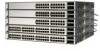
...are the same depth, and the Catalyst 3750G-12S and 3750G-24T switches...to manage switch stacks, refer to the switch software configuration guide. 3-12 Catalyst 3750 Switch Hardware Installation Guide 78-15136-02 Make sure that there is... Considerations, page 3-14 • Recommended Cabling Configurations, page 3-15 Planning Considerations Before connecting the Catalyst 3750 switches in a stack, observe these planning considerations: • Size of the StackWise cable... A, "Technical Specifications." Planning the Stack Chapter 3 Switch Installation Planning the Stack If you plan to stack...
...are the same depth, and the Catalyst 3750G-12S and 3750G-24T switches...to manage switch stacks, refer to the switch software configuration guide. 3-12 Catalyst 3750 Switch Hardware Installation Guide 78-15136-02 Make sure that there is... Considerations, page 3-14 • Recommended Cabling Configurations, page 3-15 Planning Considerations Before connecting the Catalyst 3750 switches in a stack, observe these planning considerations: • Size of the StackWise cable... A, "Technical Specifications." Planning the Stack Chapter 3 Switch Installation Planning the Stack If you plan to stack...

Hardware Installation Guide
Page 100
...and validate that is encoded with security information. These field-replaceable modules provide uplink interfaces. Use only Cisco SFP modules on the other end of SFP modules that the Catalyst 3750 switch supports. Each port must not exceed the stipulated cable length for SFP connections. Refer to...a StackWise Cable from a StackWise Port STACK 1 STACK 2 CONSOLE 86827 Installing and Removing SFP Modules These sections describe how to the Catalyst 3750 release notes for the list of the cable, and the cable must match the wave-length specifications on the Catalyst 3750 switch.
...and validate that is encoded with security information. These field-replaceable modules provide uplink interfaces. Use only Cisco SFP modules on the other end of SFP modules that the Catalyst 3750 switch supports. Each port must not exceed the stipulated cable length for SFP connections. Refer to...a StackWise Cable from a StackWise Port STACK 1 STACK 2 CONSOLE 86827 Installing and Removing SFP Modules These sections describe how to the Catalyst 3750 release notes for the list of the cable, and the cable must match the wave-length specifications on the Catalyst 3750 switch.

Hardware Installation Guide
Page 105
...on the front panel. (See Figure 3-40.) When connecting to switches or repeaters, use a crossover cable. (See the "Cable and Adapter Specifications" section on page B-6 for this feature, refer to 10BASE-T, 100BASE-TX or 1000BASE-T devices: Caution To prevent electrostatic-discharge (ESD) damage...45 connector on the other end of device on the other end 78-15136-02 Catalyst 3750 Switch Hardware Installation Guide 3-45 Step 1 When connecting to workstations, servers, routers, and Cisco IP Phones, connect a straight-through cable for copper Ethernet connections and configures the ...
...on the front panel. (See Figure 3-40.) When connecting to switches or repeaters, use a crossover cable. (See the "Cable and Adapter Specifications" section on page B-6 for this feature, refer to 10BASE-T, 100BASE-TX or 1000BASE-T devices: Caution To prevent electrostatic-discharge (ESD) damage...45 connector on the other end of device on the other end 78-15136-02 Catalyst 3750 Switch Hardware Installation Guide 3-45 Step 1 When connecting to workstations, servers, routers, and Cisco IP Phones, connect a straight-through cable for copper Ethernet connections and configures the ...

Hardware Installation Guide
Page 107
See Appendix B, "Connector and Cable Specifications" for future use. Chapter 3 Switch Installation Connecting to an SFP Module Connecting to a Fiber-Optic SFP Module Follow these steps to connect a fiber-optic cable ... the port status LED. The LED turns amber while the STP discovers the network topology and searches for solutions to cabling problems. 78-15136-02 Catalyst 3750 Switch Hardware Installation Guide 3-47 Insert one end of the fiber-optic cable into a fiber-optic receptacle on page 2-7. See Chapter 4, "Troubleshooting," for loops...
See Appendix B, "Connector and Cable Specifications" for future use. Chapter 3 Switch Installation Connecting to an SFP Module Connecting to a Fiber-Optic SFP Module Follow these steps to connect a fiber-optic cable ... the port status LED. The LED turns amber while the STP discovers the network topology and searches for solutions to cabling problems. 78-15136-02 Catalyst 3750 Switch Hardware Installation Guide 3-47 Insert one end of the fiber-optic cable into a fiber-optic receptacle on page 2-7. See Chapter 4, "Troubleshooting," for loops...

Hardware Installation Guide
Page 119
Table A-1 Specifications for the Catalyst 3750G-12S Switch Environmental Ranges Operating temperature Storage temperature Relative humidity Operating altitude Storage altitude Power Requirements AC input voltage DC input voltages...to 240 VAC (autoranging) 1.2A/0.6A, 50 to 60 Hz +12V @13A +12V @13A 120 W, 409 BTUs per hour 0.120 kVA 78-15136-02 Catalyst 3750 Switch Hardware Installation Guide A-1 A A P P E N D I X Technical Specifications This appendix lists the switch technical specifications in Table A-2, Table A-3, Table A-4, Table A-5, and the regulatory agency approvals in Table A-6.
Table A-1 Specifications for the Catalyst 3750G-12S Switch Environmental Ranges Operating temperature Storage temperature Relative humidity Operating altitude Storage altitude Power Requirements AC input voltage DC input voltages...to 240 VAC (autoranging) 1.2A/0.6A, 50 to 60 Hz +12V @13A +12V @13A 120 W, 409 BTUs per hour 0.120 kVA 78-15136-02 Catalyst 3750 Switch Hardware Installation Guide A-1 A A P P E N D I X Technical Specifications This appendix lists the switch technical specifications in Table A-2, Table A-3, Table A-4, Table A-5, and the regulatory agency approvals in Table A-6.

Hardware Installation Guide
Page 120
... Switch (continued) Environmental Ranges Physical Dimensions Weight 10 lb (4.55 kg) Dimensions (H x D x W) 1.73 x 12.83 x 17.5 in. (4.39 x 32.59 x 44.45 cm) Table A-2 Specifications for the Catalyst 3750-24TS Switch Environmental Ranges Operating temperature Storage temperature Relative humidity Operating altitude Storage altitude Power Requirements AC input voltage DC input voltages for...,000 ft (4573 m) 100 to 240 VAC (autoranging) 1.2A/0.6A, 50 to 60 Hz +12V @8.5A +12V @8.5A 50W, 171 BTUs per hour 0.083 kVA Catalyst 3750 Switch Hardware Installation Guide A-2 78-15136-02
... Switch (continued) Environmental Ranges Physical Dimensions Weight 10 lb (4.55 kg) Dimensions (H x D x W) 1.73 x 12.83 x 17.5 in. (4.39 x 32.59 x 44.45 cm) Table A-2 Specifications for the Catalyst 3750-24TS Switch Environmental Ranges Operating temperature Storage temperature Relative humidity Operating altitude Storage altitude Power Requirements AC input voltage DC input voltages for...,000 ft (4573 m) 100 to 240 VAC (autoranging) 1.2A/0.6A, 50 to 60 Hz +12V @8.5A +12V @8.5A 50W, 171 BTUs per hour 0.083 kVA Catalyst 3750 Switch Hardware Installation Guide A-2 78-15136-02

Hardware Installation Guide
Page 121
...-24TS Switch (continued) Environmental Ranges Physical Dimensions Weight 8 lb (3.6 kg) Dimensions (H x D x W) 1.73 x 11.83 x 17.5 in. (4.39 x 30.05 x 44.45 cm) Table A-3 Specifications for the Catalyst 3750G-24T Switch Environmental Ranges Operating temperature 32 to 113°F (0 to 45°C) Storage temperature -13 to 158°F (-25 to 70°C) Relative... rating 0.165 kVA Physical Dimensions Weight 10 lb (4.55 kg) Dimensions (H x D x W) 1.73 x 12.83 x 17.5 in. (4.39 x 32.59 x 44.45 cm) 78-15136-02 Catalyst 3750 Switch Hardware Installation Guide A-3
...-24TS Switch (continued) Environmental Ranges Physical Dimensions Weight 8 lb (3.6 kg) Dimensions (H x D x W) 1.73 x 11.83 x 17.5 in. (4.39 x 30.05 x 44.45 cm) Table A-3 Specifications for the Catalyst 3750G-24T Switch Environmental Ranges Operating temperature 32 to 113°F (0 to 45°C) Storage temperature -13 to 158°F (-25 to 70°C) Relative... rating 0.165 kVA Physical Dimensions Weight 10 lb (4.55 kg) Dimensions (H x D x W) 1.73 x 12.83 x 17.5 in. (4.39 x 32.59 x 44.45 cm) 78-15136-02 Catalyst 3750 Switch Hardware Installation Guide A-3

Hardware Installation Guide
Page 122
Appendix A Technical Specifications Table A-4 Specifications for the Catalyst 3750G-24TS Switch Environmental Ranges Operating temperature 32 to 113°F (0 to 45°C) Storage temperature -13 to 158°F (-25 to 70°...rating 0.190 kVA Physical Dimensions Weight 12.5 lb (5.68 kg) Dimensions (H x D x W) 2.59 x 11.60 x 17.5 in. (6.59 x 29.46 x 44.45 cm) Table A-5 Specifications for the Catalyst 3750-48TS Switch Environmental Ranges Operating temperature Storage temperature Relative humidity Operating altitude Storage altitude Power Requirements AC input voltage 32 to 113°...
Appendix A Technical Specifications Table A-4 Specifications for the Catalyst 3750G-24TS Switch Environmental Ranges Operating temperature 32 to 113°F (0 to 45°C) Storage temperature -13 to 158°F (-25 to 70°...rating 0.190 kVA Physical Dimensions Weight 12.5 lb (5.68 kg) Dimensions (H x D x W) 2.59 x 11.60 x 17.5 in. (6.59 x 29.46 x 44.45 cm) Table A-5 Specifications for the Catalyst 3750-48TS Switch Environmental Ranges Operating temperature Storage temperature Relative humidity Operating altitude Storage altitude Power Requirements AC input voltage 32 to 113°...

Hardware Installation Guide
Page 123
Appendix A Technical Specifications Table A-5 Specifications for the Catalyst 3750-48TS Switch (continued) Environmental Ranges DC input voltages for RPS 300 [email protected] DC input voltages for RPS 675 +12V @8.5A Power consumption 75W, ... BTUs per hour Power rating 0.075 kVA Physical Dimensions Weight 9.1 lb (4.1 kg) Dimensions (H x D x W) 1.73 x 11.83 x 17.5 in. (4.39 x 30.05 x 44.45 cm) Table A-6 Catalyst 3750 Switch Agency Approvals Safety EMC UL to UL 60950, Third Edition FCC Part 15 Class A c-UL to CAN/CSA -C22.2 No. 60950-00, Third...
Appendix A Technical Specifications Table A-5 Specifications for the Catalyst 3750-48TS Switch (continued) Environmental Ranges DC input voltages for RPS 300 [email protected] DC input voltages for RPS 675 +12V @8.5A Power consumption 75W, ... BTUs per hour Power rating 0.075 kVA Physical Dimensions Weight 9.1 lb (4.1 kg) Dimensions (H x D x W) 1.73 x 11.83 x 17.5 in. (4.39 x 30.05 x 44.45 cm) Table A-6 Catalyst 3750 Switch Agency Approvals Safety EMC UL to UL 60950, Third Edition FCC Part 15 Class A c-UL to CAN/CSA -C22.2 No. 60950-00, Third...

Hardware Installation Guide
Page 124
Appendix A Technical Specifications Catalyst 3750 Switch Hardware Installation Guide A-6 78-15136-02
Appendix A Technical Specifications Catalyst 3750 Switch Hardware Installation Guide A-6 78-15136-02

Hardware Installation Guide
Page 125
...Note On switches running Cisco IOS Release 12.1(14)EA1 or later, you can use either a crossover or a straight-through cable for connections to enable the automatic crossover feature. Connector Specifications These sections describe the connectors used with the Catalyst 3750 switches. 10/.... For configuration information for copper Ethernet connections and configures the interfaces accordingly. APPENDIX B Connector and Cable Specifications This appendix describes the Catalyst 3750 switch ports and the cables and adapters that you use to connect the switch to the switch software...
...Note On switches running Cisco IOS Release 12.1(14)EA1 or later, you can use either a crossover or a straight-through cable for connections to enable the automatic crossover feature. Connector Specifications These sections describe the connectors used with the Catalyst 3750 switches. 10/.... For configuration information for copper Ethernet connections and configures the interfaces accordingly. APPENDIX B Connector and Cable Specifications This appendix describes the Catalyst 3750 switch ports and the cables and adapters that you use to connect the switch to the switch software...