
Installation Guide
Page 7
... Powering On the Switch and Running POST 2-17 Connecting to the 10/100 Ports 2-18 Connecting to the GBIC Module Ports 2-20 Connecting to a 1000BaseX GBIC Module Port 2-21 Connecting to a GigaStack GBIC Module Port 2-22 Connecting a PC or Terminal to the Console Port 2-23 Assigning Switch Information 2-24 Using the Setup Program 2-25 Using BOOTP 2-29 Default Configuration Settings 2-29 Where to Go Next 2-31 Troubleshooting 3-1 Understanding POST Results 3-2 Diagnosing Problems 3-3 Contents 78-6456-03 Catalyst 3500 Series XL Hardware Installation Guide...
... Powering On the Switch and Running POST 2-17 Connecting to the 10/100 Ports 2-18 Connecting to the GBIC Module Ports 2-20 Connecting to a 1000BaseX GBIC Module Port 2-21 Connecting to a GigaStack GBIC Module Port 2-22 Connecting a PC or Terminal to the Console Port 2-23 Assigning Switch Information 2-24 Using the Setup Program 2-25 Using BOOTP 2-29 Default Configuration Settings 2-29 Where to Go Next 2-31 Troubleshooting 3-1 Understanding POST Results 3-2 Diagnosing Problems 3-3 Contents 78-6456-03 Catalyst 3500 Series XL Hardware Installation Guide...

Installation Guide
Page 25
... such as backbone switches, aggregating 10/100 and Gigabit Ethernet traffic from other switches. A feature specific to the Catalyst 3524-PWR XL switch is its ability to provide inline power to Cisco IP Phones. (Phone adapters are not required when connecting to the Catalyst 3524-PWR XL 10/100 switch ports.) Figure 1-1 shows the switch models in different network topologies Features The Catalyst 3500 series XL switches-also referred to as Catalyst 3500 XL switches-are stackable 10/100 Ethernet switches to which...
... such as backbone switches, aggregating 10/100 and Gigabit Ethernet traffic from other switches. A feature specific to the Catalyst 3524-PWR XL switch is its ability to provide inline power to Cisco IP Phones. (Phone adapters are not required when connecting to the Catalyst 3524-PWR XL 10/100 switch ports.) Figure 1-1 shows the switch models in different network topologies Features The Catalyst 3500 series XL switches-also referred to as Catalyst 3500 XL switches-are stackable 10/100 Ethernet switches to which...

Installation Guide
Page 26
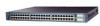
... 1-1 Catalyst 3500 Series XL Switches Switch Description WS-C3508G-XL 8 GBIC1-based gigabit module slots 1 SYSTEM 2 3 RPS 4 5 MODE STATUS UTIL DUPLX SPEED 6 7 8 WS-C3512-XL 12 autosensing10/100 Ethernet ports 2 GBIC-based gigabit module slots WS-C3524-XL 24 autosensing 10/100 Ethernet ports 2 fixed GBIC-based gigabit module slots WS-C3524-PWR-XL 24 autosensing 10/100 inline-power Ethernet ports 2 GBIC-based gigabit module slots WS-C3548-XL 48 autosensing 10/100 Ethernet ports 2 GBIC-based gigabit module slots 1. GBIC = Gigabit Interface Converter MODE SYSTEM...
... 1-1 Catalyst 3500 Series XL Switches Switch Description WS-C3508G-XL 8 GBIC1-based gigabit module slots 1 SYSTEM 2 3 RPS 4 5 MODE STATUS UTIL DUPLX SPEED 6 7 8 WS-C3512-XL 12 autosensing10/100 Ethernet ports 2 GBIC-based gigabit module slots WS-C3524-XL 24 autosensing 10/100 Ethernet ports 2 fixed GBIC-based gigabit module slots WS-C3524-PWR-XL 24 autosensing 10/100 inline-power Ethernet ports 2 GBIC-based gigabit module slots WS-C3548-XL 48 autosensing 10/100 Ethernet ports 2 GBIC-based gigabit module slots 1. GBIC = Gigabit Interface Converter MODE SYSTEM...

Installation Guide
Page 27
... multicast traffic • Broadcast storm control to prevent performance degradation from broadcast storms • Switch Port Analyzer (SPAN) port monitoring on any port • Support for command switch redundancy • Support for optional Cisco 600W Redundant Power System (RPS) that operates on AC input and supplies DC output to four 1000BaseZX GBICs with the Catalyst 3508G XL switch) Management • Cisco IOS command-line interface (CLI) through the console port or Telnet • CiscoView device-management application • Cluster Management Suite, a web...
... multicast traffic • Broadcast storm control to prevent performance degradation from broadcast storms • Switch Port Analyzer (SPAN) port monitoring on any port • Support for command switch redundancy • Support for optional Cisco 600W Redundant Power System (RPS) that operates on AC input and supplies DC output to four 1000BaseZX GBICs with the Catalyst 3508G XL switch) Management • Cisco IOS command-line interface (CLI) through the console port or Telnet • CiscoView device-management application • Cluster Management Suite, a web...

Installation Guide
Page 28
... VLANs • ISL and IEEE 802.1Q trunking support on all ports • Support for voice VLAN ID (VVID) • High-speed EtherChannel connections between switches and servers • 8192 MAC addresses • IEEE 802.1p capable • CGMP to limit the flooding of IP multicast traffic • Broadcast storm control to prevent performance degradation from broadcast storms • SPAN port monitoring on any port • Support for command switch redundancy • Support for Cisco GBIC modules...
... VLANs • ISL and IEEE 802.1Q trunking support on all ports • Support for voice VLAN ID (VVID) • High-speed EtherChannel connections between switches and servers • 8192 MAC addresses • IEEE 802.1p capable • CGMP to limit the flooding of IP multicast traffic • Broadcast storm control to prevent performance degradation from broadcast storms • SPAN port monitoring on any port • Support for command switch redundancy • Support for Cisco GBIC modules...

Installation Guide
Page 29
...; Connection for optional Cisco RPS 600 that operates on all 10/100 ports • Support for optional Cisco RPS 300 that you press.) These front-panel components are described in this section. 78-6456-04 Catalyst 3500 Series XL Hardware Installation Guide 1-5 The front panel of the Catalyst 3512, 3524, 3524-PWR and 3548 XL switches (Figure 1-3, Figure 1-4, Figure 1-5, and Figure 1-6) have a set of LEDs and a Mode button...
...; Connection for optional Cisco RPS 600 that operates on all 10/100 ports • Support for optional Cisco RPS 300 that you press.) These front-panel components are described in this section. 78-6456-04 Catalyst 3500 Series XL Hardware Installation Guide 1-5 The front panel of the Catalyst 3512, 3524, 3524-PWR and 3548 XL switches (Figure 1-3, Figure 1-4, Figure 1-5, and Figure 1-6) have a set of LEDs and a Mode button...

Installation Guide
Page 31
... hubs through standard RJ-45 connectors and Category 3, 4, or 5 cabling 78-6456-04 Catalyst 3500 Series XL Hardware Installation Guide 1-7 The first member of 100 meters, to a distance of the pair (port 1) is above the second member (port 2). Chapter 1 Product Overview Figure 1-5 Catalyst 3524-PWR XL Switch Front-Panel Description 30291 12 1X 34 56 78 MODE SYSTEM RPS STATUS 2X DUPLX SPEED LINE PWR 9 10 11...
... hubs through standard RJ-45 connectors and Category 3, 4, or 5 cabling 78-6456-04 Catalyst 3500 Series XL Hardware Installation Guide 1-7 The first member of 100 meters, to a distance of the pair (port 1) is above the second member (port 2). Chapter 1 Product Overview Figure 1-5 Catalyst 3524-PWR XL Switch Front-Panel Description 30291 12 1X 34 56 78 MODE SYSTEM RPS STATUS 2X DUPLX SPEED LINE PWR 9 10 11...

Installation Guide
Page 32
... is required for 100BaseTX traffic. The 10/100 ports on the Catalyst 3512, 3524, and 3548 XL switches-must be set for inline power on a port, the port Catalyst 3500 Series XL Hardware Installation Guide 1-8 78-6456-04 Refer to the Cisco IOS Desktop Switching Software Configuration Guide for more information about these cables do not work for ports operating at 10 Mbps can : • Provide -48V DC power to the 10/100 ports on the Catalyst 3512, 3524, 3524...
... is required for 100BaseTX traffic. The 10/100 ports on the Catalyst 3512, 3524, and 3548 XL switches-must be set for inline power on a port, the port Catalyst 3500 Series XL Hardware Installation Guide 1-8 78-6456-04 Refer to the Cisco IOS Desktop Switching Software Configuration Guide for more information about these cables do not work for ports operating at 10 Mbps can : • Provide -48V DC power to the 10/100 ports on the Catalyst 3512, 3524, 3524...

Installation Guide
Page 33
..., refer to the documentation that came with your Cisco IP Phone. Using the required Cisco proprietary signaling and cabling, the maximum distance for creating a 1-Gbps stack configuration of up to nine Catalyst 3500 XL switches. GBIC Module Slots The Cisco Gigabit Interface Converter (GBIC) module slots support the following modules to provide flexibility in a point-to-point configuration) or up to which the Cisco IP Phone is first connected becomes its backup...
..., refer to the documentation that came with your Cisco IP Phone. Using the required Cisco proprietary signaling and cabling, the maximum distance for creating a 1-Gbps stack configuration of up to nine Catalyst 3500 XL switches. GBIC Module Slots The Cisco Gigabit Interface Converter (GBIC) module slots support the following modules to provide flexibility in a point-to-point configuration) or up to which the Cisco IP Phone is first connected becomes its backup...

Installation Guide
Page 40
... Cisco RPS 300, refer to interpret the port LED colors after you change a mode, press the Mode button until the desired mode is lost. The port modes (Table 1-6) determine the type of the switch is down , or a fan on the RPS. To select or change port modes, the meaning of the power supplies in the Catalyst 3548 XL switch, press the Mode label. Table 1-7 and Table 1-8 explain how to the Cisco Redundant Power System 300 Hardware Installation Guide. When you change the port mode...
... Cisco RPS 300, refer to interpret the port LED colors after you change a mode, press the Mode button until the desired mode is lost. The port modes (Table 1-6) determine the type of the switch is down , or a fan on the RPS. To select or change port modes, the meaning of the power supplies in the Catalyst 3548 XL switch, press the Mode label. Table 1-7 and Table 1-8 explain how to the Cisco Redundant Power System 300 Hardware Installation Guide. When you change the port mode...

Installation Guide
Page 41
... (port status) UTL (utilization) DUPLEX LED Color Off Solid green Flashing green Alternating green-amber Solid amber Green Off Green Meaning No link. The inline power status: on a logarithmic scale. Port is transmitting or receiving data. Chapter 1 Product Overview Front-Panel Description Table 1-6 Port Mode LEDs (continued) Mode LED DUPLX SPEED LINE PWR Port Mode Port duplex mode Port speed Port inline power Description The port duplex mode: full duplex or half duplex. Port is not forwarding. Port was disabled by management or an address violation or was blocked by Spanning Tree...
... (port status) UTL (utilization) DUPLEX LED Color Off Solid green Flashing green Alternating green-amber Solid amber Green Off Green Meaning No link. The inline power status: on a logarithmic scale. Port is transmitting or receiving data. Chapter 1 Product Overview Front-Panel Description Table 1-6 Port Mode LEDs (continued) Mode LED DUPLX SPEED LINE PWR Port Mode Port duplex mode Port speed Port inline power Description The port duplex mode: full duplex or half duplex. Port is not forwarding. Port was disabled by management or an address violation or was blocked by Spanning Tree...
Installation Guide
Page 49
...data. Network Configuration Examples This section provides network configuration concepts and includes examples of the switch, to access the CLI. The switch supports a comprehensive set configuration parameters and to view switch status and performance information. Chapter 1 Product Overview Network Configuration Examples • Cisco IOS command-line interface (CLI) Connect a PC or terminal directly to the console port, located on the rear panel of using the switch to create dedicated network segments and interconnecting the segments through Fast Ethernet and Gigabit Ethernet...
...data. Network Configuration Examples This section provides network configuration concepts and includes examples of the switch, to access the CLI. The switch supports a comprehensive set configuration parameters and to view switch status and performance information. Chapter 1 Product Overview Network Configuration Examples • Cisco IOS command-line interface (CLI) Connect a PC or terminal directly to the console port, located on the rear panel of using the switch to create dedicated network segments and interconnecting the segments through Fast Ethernet and Gigabit Ethernet...

Installation Guide
Page 50
... routers to which network users require equal access-directly to the Fast Ethernet or Gigabit Ethernet switch ports so that support at least two queues per port to create a GigaStack loopback. 1-26 Catalyst 3500 Series XL Hardware Installation Guide 78-6456-04 Use switches that they have their own Fast Ethernet or Gigabit Ethernet segment. • Use the Fast EtherChannel or Gigabit EtherChannel feature between the switch and its connected workstations. • The increased power of users accessing the Internet • Create smaller network...
... routers to which network users require equal access-directly to the Fast Ethernet or Gigabit Ethernet switch ports so that support at least two queues per port to create a GigaStack loopback. 1-26 Catalyst 3500 Series XL Hardware Installation Guide 78-6456-04 Use switches that they have their own Fast Ethernet or Gigabit Ethernet segment. • Use the Fast EtherChannel or Gigabit EtherChannel feature between the switch and its connected workstations. • The increased power of users accessing the Internet • Create smaller network...
Installation Guide
Page 53
... line. 78-6456-04 Catalyst 3500 Series XL Hardware Installation Guide 1-29 to the 10/100 switch ports for redundant cluster management. The Catalyst 3500 XL switches in this network are connected to the Internet through a GigaStack GBIC on each user and improving server response time. When a workstation is a high-bandwidth connection (such as a switch cluster, with primary and secondary command switches for their own 10- This GigaStack also can be configured as Fast Ethernet or Gigabit Ethernet...
... line. 78-6456-04 Catalyst 3500 Series XL Hardware Installation Guide 1-29 to the 10/100 switch ports for redundant cluster management. The Catalyst 3500 XL switches in this network are connected to the Internet through a GigaStack GBIC on each user and improving server response time. When a workstation is a high-bandwidth connection (such as a switch cluster, with primary and secondary command switches for their own 10- This GigaStack also can be configured as Fast Ethernet or Gigabit Ethernet...

Installation Guide
Page 55
...-VLAN routing and allows the router to voice traffic over data traffic. The workgroups are connected-using standard straight-through the IP address of its primary and secondary command switches, regardless of the geographic location of approximately 500 employees. Using the Cisco Cluster Management Suite, you can manage a cluster through , twisted-pair cable with workstations running Cisco CallManager software, a Dynamic Host Configuration Protocol (DHCP)/Bootstrap Protocol (BOOTP) server, or an IPTV multicast server...
...-VLAN routing and allows the router to voice traffic over data traffic. The workgroups are connected-using standard straight-through the IP address of its primary and secondary command switches, regardless of the geographic location of approximately 500 employees. Using the Cisco Cluster Management Suite, you can manage a cluster through , twisted-pair cable with workstations running Cisco CallManager software, a Dynamic Host Configuration Protocol (DHCP)/Bootstrap Protocol (BOOTP) server, or an IPTV multicast server...
Installation Guide
Page 76
... port LEDs return to the status mode display, indicating that have their speed and duplex parameters manually set the speed and duplex parameters. If POST fails, refer to Chapter 3, "Troubleshooting," to determine a course of the connection. POST failures are usually fatal. If the attached ports do not support autonegotiation, you must wait 10 seconds before connecting another network device (other than another Cisco IP Phone) to that switch port. You can configure the 10/100 ports...
... port LEDs return to the status mode display, indicating that have their speed and duplex parameters manually set the speed and duplex parameters. If POST fails, refer to Chapter 3, "Troubleshooting," to determine a course of the connection. POST failures are usually fatal. If the attached ports do not support autonegotiation, you must wait 10 seconds before connecting another network device (other than another Cisco IP Phone) to that switch port. You can configure the 10/100 ports...
Installation Guide
Page 77
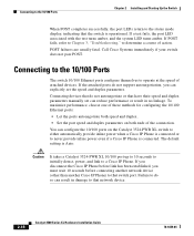
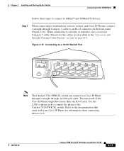
..., servers, routers, and Cisco IP Phones, connect a straight-through , twisted-pair cable. When connecting to an RJ-45 connector on page B-4. Figure 2-10 Connecting to a 10/100 Switch Port MODE SYSTEM RPS STATUS UTIL DUPLX SPEED 12 1X 2X 34 56 78 9 10 11 12 11X 12X 22001 Note The Catalyst 3524-PWR XL switch can connect to a Cisco IP Phone through a straight-through Category 5 cable to switches or repeaters, use a crossover Category 5 cable.
..., servers, routers, and Cisco IP Phones, connect a straight-through , twisted-pair cable. When connecting to an RJ-45 connector on page B-4. Figure 2-10 Connecting to a 10/100 Switch Port MODE SYSTEM RPS STATUS UTIL DUPLX SPEED 12 1X 2X 34 56 78 9 10 11 12 11X 12X 22001 Note The Catalyst 3524-PWR XL switch can connect to a Cisco IP Phone through a straight-through Category 5 cable to switches or repeaters, use a crossover Category 5 cable.
Installation Guide
Page 83
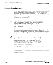
To run the setup program, access the switch from your configuration. Refer to communicate with local routers and the Internet. Later, you can use the Cluster Management Suite or the command-line interface (CLI) to customize your system administrator: Switch IP address Subnet mask (netmask 78-6456-04 Catalyst 3500 Series XL Hardware Installation Guide 2-25 Note If the switch will be a cluster member managed through the IP address of the command switch, it is...
To run the setup program, access the switch from your configuration. Refer to communicate with local routers and the Internet. Later, you can use the Cluster Management Suite or the command-line interface (CLI) to customize your system administrator: Switch IP address Subnet mask (netmask 78-6456-04 Catalyst 3500 Series XL Hardware Installation Guide 2-25 Note If the switch will be a cluster member managed through the IP address of the command switch, it is...

Installation Guide
Page 91
...3 Troubleshooting The LEDs on self-test (POST), port-connectivity problems, and overall switch performance. See the Cisco IOS Desktop Switching Software Configuration Guide, the Cisco IOS Desktop Switching Command Reference (online only), or the documentation that came with your SNMP application for troubleshooting problems: • Understanding POST results • Diagnosing problems 78-6456-04 Catalyst 3500 Series XL Hardware Installation Guide 3-1 You can also get statistics from the browser interface, from the command-line interface (CLI), or from an Simple Network Management...
...3 Troubleshooting The LEDs on self-test (POST), port-connectivity problems, and overall switch performance. See the Cisco IOS Desktop Switching Software Configuration Guide, the Cisco IOS Desktop Switching Command Reference (online only), or the documentation that came with your SNMP application for troubleshooting problems: • Understanding POST results • Diagnosing problems 78-6456-04 Catalyst 3500 Series XL Hardware Installation Guide 3-1 You can also get statistics from the browser interface, from the command-line interface (CLI), or from an Simple Network Management...
Installation Guide
Page 154
... LED 1-15 Cisco SoftPhone software 1-31 CiscoView 1-25 Cluster Builder application 1-24 Cluster Management Suite 1-24 Cluster Manager application 1-24 Cluster View application 1-24 command-line interface (CLI) 1-25 configuration, default values 2-30 configuration examples, network 1-25 connecting to 10/100 ports 2-18 to 1000BaseX ports 2-20 to console port 2-18, B-3 to GBICs 2-21 to GigaStack GBICs 2-22 connection procedures 2-18 to 2-24 connectivity problems, solving 3-3 connectors and cables 10/100 ports B-1 to B-2 1000BaseX ports B-2 to B-3 console port B-3 to B-7 GigaStack GBICs B-3 power...
... LED 1-15 Cisco SoftPhone software 1-31 CiscoView 1-25 Cluster Builder application 1-24 Cluster Management Suite 1-24 Cluster Manager application 1-24 Cluster View application 1-24 command-line interface (CLI) 1-25 configuration, default values 2-30 configuration examples, network 1-25 connecting to 10/100 ports 2-18 to 1000BaseX ports 2-20 to console port 2-18, B-3 to GBICs 2-21 to GigaStack GBICs 2-22 connection procedures 2-18 to 2-24 connectivity problems, solving 3-3 connectors and cables 10/100 ports B-1 to B-2 1000BaseX ports B-2 to B-3 console port B-3 to B-7 GigaStack GBICs B-3 power...


