
Installation Guide
Page 2
.... You can radiate radio-frequency energy and, if not installed and used in accordance with the instruction manual, may cause interference with the specifications in part 15 of Class B devices: The equipment described in this equipment in a residential area is for a Class B digital device in...part 15 of this manual generates and may be required to this product not authorized by the Cisco equipment or one side or the other of its peripheral devices. These specifications are on a different circuit from the television or radio. (That is operated in accordance with...
.... You can radiate radio-frequency energy and, if not installed and used in accordance with the instruction manual, may cause interference with the specifications in part 15 of Class B devices: The equipment described in this equipment in a residential area is for a Class B digital device in...part 15 of this manual generates and may be required to this product not authorized by the Cisco equipment or one side or the other of its peripheral devices. These specifications are on a different circuit from the television or radio. (That is operated in accordance with...

Installation Guide
Page 8
...) C-2 Attaching the Cisco RPS (model PWR300-AC-RPS-N1) C-4 Service Personnel Warning C-5 Qualified Personnel Warning C-7 Installation Instructions Warning C-9 Jewelry Removal Warning C-10 Stacking the Chassis Warning C-13 Main Disconnecting Device C-15 Overtemperature Warning C-16 TN Power Warning C-19 Ground Connection Warning C-20 Circuit Breaker (15A) Warning C-21 Catalyst 3500 Series XL Hardware Installation...
...) C-2 Attaching the Cisco RPS (model PWR300-AC-RPS-N1) C-4 Service Personnel Warning C-5 Qualified Personnel Warning C-7 Installation Instructions Warning C-9 Jewelry Removal Warning C-10 Stacking the Chassis Warning C-13 Main Disconnecting Device C-15 Overtemperature Warning C-16 TN Power Warning C-19 Ground Connection Warning C-20 Circuit Breaker (15A) Warning C-21 Catalyst 3500 Series XL Hardware Installation...

Installation Guide
Page 12
... that might arise when you are installing the switch. Catalyst 3500 Series XL Hardware Installation Guide xii 78-6456-04 Appendix A, "Technical Specifications," lists the physical and environmental specifications for installing a switch on a rack, wall, table, or shelf. It describes the switch ports, the standards they support, and the switch LEDs. Conventions This guide uses the following chapters...
... that might arise when you are installing the switch. Catalyst 3500 Series XL Hardware Installation Guide xii 78-6456-04 Appendix A, "Technical Specifications," lists the physical and environmental specifications for installing a switch on a rack, wall, table, or shelf. It describes the switch ports, the standards they support, and the switch LEDs. Conventions This guide uses the following chapters...

Installation Guide
Page 25
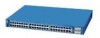
... from other switches. A feature specific to the Catalyst 3524-PWR XL switch is its ability to provide inline power to Cisco IP Phones. (Phone adapters are not required when connecting to the Catalyst 3524-PWR XL 10/100 switch ports.) Figure 1-1 shows the switch models in different network topologies Features The Catalyst 3500 series XL switches-also referred to as Catalyst 3500 XL switches-are stackable...
... from other switches. A feature specific to the Catalyst 3524-PWR XL switch is its ability to provide inline power to Cisco IP Phones. (Phone adapters are not required when connecting to the Catalyst 3524-PWR XL 10/100 switch ports.) Figure 1-1 shows the switch models in different network topologies Features The Catalyst 3500 series XL switches-also referred to as Catalyst 3500 XL switches-are stackable...

Installation Guide
Page 32
... When connecting the switch to operate in Appendix B, "Connector and Cable Specifications." Ports operating at 100 Mbps. Pinouts for ports operating at 10 Mbps can be sure that is connected. The 10/100 switch ports can be connected to the Cisco IOS Desktop Switching Software Configuration Guide ... are described in any combination of the attached device and advertises its own capabilities. Cisco IP Phones-connected to the 10/100 ports on the Catalyst 3512, 3524, and 3548 XL switches-must be explicitly set for speed and duplex autonegotiation, compliant with IEEE 802.3u....
... When connecting the switch to operate in Appendix B, "Connector and Cable Specifications." Ports operating at 100 Mbps. Pinouts for ports operating at 10 Mbps can be sure that is connected. The 10/100 switch ports can be connected to the Cisco IOS Desktop Switching Software Configuration Guide ... are described in any combination of the attached device and advertises its own capabilities. Cisco IP Phones-connected to the 10/100 ports on the Catalyst 3512, 3524, and 3548 XL switches-must be explicitly set for speed and duplex autonegotiation, compliant with IEEE 802.3u....

Installation Guide
Page 47
... to a powered-on RPS. For more information on the Catalyst 3508, 3512, 3524, and 3548 XL Switches The Cisco RPS 600 (model PWR600-AC-RPS) provides a quasi-redundant power source for the Cisco RPS and one connector at each external device. If you ...the switch is not recommended. Cisco RPS Connector Specific Cisco RPS models support specific Catalyst 3500 XL switches: • Cisco RPS 600 (model PWR600-AC-RPS)-Supports the Catalyst 3512, 3524, 3548, and 3508 XL switches • Cisco RPS 300 (model PWR300-AC-RPS)-Supports the Catalyst 3524-PWR XL switch RPS Connector on the Cisco RPS...
... to a powered-on RPS. For more information on the Catalyst 3508, 3512, 3524, and 3548 XL Switches The Cisco RPS 600 (model PWR600-AC-RPS) provides a quasi-redundant power source for the Cisco RPS and one connector at each external device. If you ...the switch is not recommended. Cisco RPS Connector Specific Cisco RPS models support specific Catalyst 3500 XL switches: • Cisco RPS 600 (model PWR600-AC-RPS)-Supports the Catalyst 3512, 3524, 3548, and 3508 XL switches • Cisco RPS 300 (model PWR300-AC-RPS)-Supports the Catalyst 3524-PWR XL switch RPS Connector on the Cisco RPS...

Installation Guide
Page 48
..., and Cluster Manager applications to six switches, it can connect a Catalyst 3500 XL switch to the affected switch. If more information on page B-4. For console port and adapter pinout information, see the "Cable and Adapter Specifications" section on the Cisco RPS 300, refer to six switches. Although it supports up to the Cisco Redundant Power System 300 Hardware Installation...
..., and Cluster Manager applications to six switches, it can connect a Catalyst 3500 XL switch to the affected switch. If more information on page B-4. For console port and adapter pinout information, see the "Cable and Adapter Specifications" section on the Cisco RPS 300, refer to six switches. Although it supports up to the Cisco Redundant Power System 300 Hardware Installation...

Installation Guide
Page 65
...typical commercial establishments for Installation Warning This equipment is within the ranges listed in Appendix A, "Technical Specifications." 78-6456-04 Catalyst 3500 Series XL Hardware Installation Guide 2-7 For specific cable lengths, refer to the document that came with your GBICs. • For the GigaStack... GBIC ports, cable lengths from the switch to the connected devices are up to 1 meter. For specific cable ...
...typical commercial establishments for Installation Warning This equipment is within the ranges listed in Appendix A, "Technical Specifications." 78-6456-04 Catalyst 3500 Series XL Hardware Installation Guide 2-7 For specific cable lengths, refer to the document that came with your GBICs. • For the GigaStack... GBIC ports, cable lengths from the switch to the connected devices are up to 1 meter. For specific cable ...

Installation Guide
Page 81
...-DSBUASYN=) containing that your PC or terminal possible during the setup program. See the Cisco IOS Desktop Switching Software Configuration Guide for instructions. 78-6456-04 Catalyst 3500 Series XL Hardware Installation Guide 2-23 The terminal-emulation software-frequently a PC application such as Hyperterminal...For more information on the GigaStack GBIC connections and configuration scenarios, see the "Cable and Adapter Specifications" section on page B-4. Chapter 2 Installing and Starting Up the Switch Connecting a PC or Terminal to a terminal. You need to provide a RJ-45-to-DB...
...-DSBUASYN=) containing that your PC or terminal possible during the setup program. See the Cisco IOS Desktop Switching Software Configuration Guide for instructions. 78-6456-04 Catalyst 3500 Series XL Hardware Installation Guide 2-23 The terminal-emulation software-frequently a PC application such as Hyperterminal...For more information on the GigaStack GBIC connections and configuration scenarios, see the "Cable and Adapter Specifications" section on page B-4. Chapter 2 Installing and Starting Up the Switch Connecting a PC or Terminal to a terminal. You need to provide a RJ-45-to-DB...

Installation Guide
Page 84
...Enter Y to specify a default gateway (router): Would you want to connect the switch console port to the switch console port. For console port and adapter pinout information, see the "Cable and Adapter Specifications" section on page B-4. Use the supplied rollover cable and DB-9 adapter to connect... adapter from Cisco. Enter setup, and press Return to restart the setup program. The data characteristics are 9600 baud, 8 data bits, 1 stop bit, and no ]: y If this procedure to create an initial configuration for the switch, and press Return: 2-26 Catalyst 3500 Series XL Hardware Installation...
...Enter Y to specify a default gateway (router): Would you want to connect the switch console port to the switch console port. For console port and adapter pinout information, see the "Cable and Adapter Specifications" section on page B-4. Use the supplied rollover cable and DB-9 adapter to connect... adapter from Cisco. Enter setup, and press Return to restart the setup program. The data characteristics are 9600 baud, 8 data bits, 1 stop bit, and no ]: y If this procedure to create an initial configuration for the switch, and press Return: 2-26 Catalyst 3500 Series XL Hardware Installation...

Installation Guide
Page 97
Table A-4 lists the regulatory agency approvals. Table A-1 Technical Specifications for the Catalyst 3500 series XL switches. A A P P E N D I X Technical Specifications 78-6456-04 Table A-1, Table A-2, and Table A-3, list the technical specifications for the Catalyst 3508G XL Switch Environmental Ranges Operating temperature Storage temperature Operating humidity Operating altitude Storage altitude Power Requirements AC input voltage DC ...@3A 82.2W 280 Btus per hour 12 lb (5.45 kg) 1.75 x 16 x 17.5 in. (4.45 x 40.46 x 44.45 cm) Catalyst 3500 Series XL Hardware Installation Guide A-1
Table A-4 lists the regulatory agency approvals. Table A-1 Technical Specifications for the Catalyst 3500 series XL switches. A A P P E N D I X Technical Specifications 78-6456-04 Table A-1, Table A-2, and Table A-3, list the technical specifications for the Catalyst 3508G XL Switch Environmental Ranges Operating temperature Storage temperature Operating humidity Operating altitude Storage altitude Power Requirements AC input voltage DC ...@3A 82.2W 280 Btus per hour 12 lb (5.45 kg) 1.75 x 16 x 17.5 in. (4.45 x 40.46 x 44.45 cm) Catalyst 3500 Series XL Hardware Installation Guide A-1

Installation Guide
Page 98
Appendix A Technical Specifications Table A-2 Technical Specifications for the Catalyst 3512, 3524, and 3548 XL Switches Catalyst 3512 XL Catalyst 3524 XL Catalyst 3548 XL Environmental Ranges Operating temperature 32 to 113°F (0 to 45°C) 32 to 113°F (0 to 45°C) 32 to 113°F (0 to 45°C) ....82 x 17.5 in. 1.73 x 15.34 x 17.5 in D x W) (4.45 x 30.02 x 44.45 cm) (4.45 x 30.02 x 44.45 cm) (4.39 x 39.0 x 44.45 cm) Catalyst 3500 Series XL Hardware Installation Guide A-2 78-6456-04
Appendix A Technical Specifications Table A-2 Technical Specifications for the Catalyst 3512, 3524, and 3548 XL Switches Catalyst 3512 XL Catalyst 3524 XL Catalyst 3548 XL Environmental Ranges Operating temperature 32 to 113°F (0 to 45°C) 32 to 113°F (0 to 45°C) 32 to 113°F (0 to 45°C) ....82 x 17.5 in. 1.73 x 15.34 x 17.5 in D x W) (4.45 x 30.02 x 44.45 cm) (4.45 x 30.02 x 44.45 cm) (4.39 x 39.0 x 44.45 cm) Catalyst 3500 Series XL Hardware Installation Guide A-2 78-6456-04

Installation Guide
Page 99
Table A-4 Catalyst 3500 Series XL Agency Approvals Safety EMC UL to UL 1950, Third Edition FCC Part 15 Class A c-UL to CAN/CSA 22.2 No. 950-95, Third Edition EN 55022 Class A (CISPR 22 Class A) TUV/GS to EN 60950 with Amendment A1-A4 and A11 VCCI Class... (H x W x D) 1.75 x 11.82 x 17.5 in. (4.45 x 30.02 x 44.45 cm) 1. Appendix A Technical Specifications Table A-3 Technical Specifications for the Catalyst 3524-PWR XL Switch Environmental Ranges Operating temperature 32 to 113°F (0 to 45°C) Storage temperature -4 to 149°F (-10 to 65°C) Operating humidity...
Table A-4 Catalyst 3500 Series XL Agency Approvals Safety EMC UL to UL 1950, Third Edition FCC Part 15 Class A c-UL to CAN/CSA 22.2 No. 950-95, Third Edition EN 55022 Class A (CISPR 22 Class A) TUV/GS to EN 60950 with Amendment A1-A4 and A11 VCCI Class... (H x W x D) 1.75 x 11.82 x 17.5 in. (4.45 x 30.02 x 44.45 cm) 1. Appendix A Technical Specifications Table A-3 Technical Specifications for the Catalyst 3524-PWR XL Switch Environmental Ranges Operating temperature 32 to 113°F (0 to 45°C) Storage temperature -4 to 149°F (-10 to 65°C) Operating humidity...

Installation Guide
Page 100
Appendix A Technical Specifications Catalyst 3500 Series XL Hardware Installation Guide A-4 78-6456-04
Appendix A Technical Specifications Catalyst 3500 Series XL Hardware Installation Guide A-4 78-6456-04

Installation Guide
Page 101
...Cisco IP Phones, you must use a straight-through cable wired for 10BaseT and 100BaseTX (Figure B-5 illustrates the straight-through cable to connect two ports when one of the ports is designated with an X. When connecting to other devices. Figure B-1 shows the pinout. APPENDIX B Connector and Cable Specifications This appendix describes the Catalyst 3500 XL switch... ports and the cables and adapters that you use to connect the switch to other switches or repeaters, ensure that a ...
...Cisco IP Phones, you must use a straight-through cable wired for 10BaseT and 100BaseTX (Figure B-5 illustrates the straight-through cable to connect two ports when one of the ports is designated with an X. When connecting to other devices. Figure B-1 shows the pinout. APPENDIX B Connector and Cable Specifications This appendix describes the Catalyst 3500 XL switch... ports and the cables and adapters that you use to connect the switch to other switches or repeaters, ensure that a ...

Installation Guide
Page 102
Connector Specifications Appendix B Connector and Cable Specifications Figure B-1 10/100 Port Pinouts Pin Label 1 RD+ 2 RD- 3 TD+ 4 NC 5 NC 6 TD- 7 NC 8 NC 12345678 H5318 1000BaseX Ports 1000BaseX ports use duplex SC connectors, as shown in Figure B-2. Figure B-2 1000BaseX SC Connector H8707 Tx Rx Catalyst 3500 Series XL Hardware Installation Guide B-2 78-6456-04
Connector Specifications Appendix B Connector and Cable Specifications Figure B-1 10/100 Port Pinouts Pin Label 1 RD+ 2 RD- 3 TD+ 4 NC 5 NC 6 TD- 7 NC 8 NC 12345678 H5318 1000BaseX Ports 1000BaseX ports use duplex SC connectors, as shown in Figure B-2. Figure B-2 1000BaseX SC Connector H8707 Tx Rx Catalyst 3500 Series XL Hardware Installation Guide B-2 78-6456-04

Installation Guide
Page 103
...45 rollover cable and DB-9 adapter are proprietary, high-data-rate cables with the GigaStack GBIC. Appendix B Connector and Cable Specifications Connector Specifications Gigastack Port The GigaStack Gigabit Interface Converter (GBIC) uses proprietary connectors, as shown in Table B-1 and Table B-2. Caution Do ...adapter from Cisco. You need to provide a RJ-45-to-DB-25 female DTE adapter if you want to connect the switch console port to a console PC. For console port and adapter pinout information, see Table B-1 and Table B-2. 78-6456-04 Catalyst 3500 Series XL Hardware Installation...
...45 rollover cable and DB-9 adapter are proprietary, high-data-rate cables with the GigaStack GBIC. Appendix B Connector and Cable Specifications Connector Specifications Gigastack Port The GigaStack Gigabit Interface Converter (GBIC) uses proprietary connectors, as shown in Table B-1 and Table B-2. Caution Do ...adapter from Cisco. You need to provide a RJ-45-to-DB-25 female DTE adapter if you want to connect the switch console port to a console PC. For console port and adapter pinout information, see Table B-1 and Table B-2. 78-6456-04 Catalyst 3500 Series XL Hardware Installation...

Installation Guide
Page 104
Switch 3 RD+ 6 RD- 1 RD+ 2 RD- 1 TD+ 2 TD- H5578 Catalyst 3500 Series XL Hardware Installation Guide B-4 78-6456-04 Switch 3 TD+ 6 TD- 1 RD+ 2 RD- 1 RD+ 2 RD- Figure B-4 Crossover Cable Schematic Switch 3 TD+ 6 TD- H5579 Figure B-5 Straight-Through Cable Schematic Switch 3 TD+ 6 TD- Cable and Adapter Specifications Appendix B Connector and Cable Specifications Cable and Adapter Specifications Crossover and Straight-Through Cable Pinouts The schematics of crossover and straight-through cables are shown in Figure B-4 and Figure B-5.
Switch 3 RD+ 6 RD- 1 RD+ 2 RD- 1 TD+ 2 TD- H5578 Catalyst 3500 Series XL Hardware Installation Guide B-4 78-6456-04 Switch 3 TD+ 6 TD- 1 RD+ 2 RD- 1 RD+ 2 RD- Figure B-4 Crossover Cable Schematic Switch 3 TD+ 6 TD- H5579 Figure B-5 Straight-Through Cable Schematic Switch 3 TD+ 6 TD- Cable and Adapter Specifications Appendix B Connector and Cable Specifications Cable and Adapter Specifications Crossover and Straight-Through Cable Pinouts The schematics of crossover and straight-through cables are shown in Figure B-4 and Figure B-5.

Installation Guide
Page 105
... the other connector should be the same color. Pin 8 H10632 78-6456-04 Catalyst 3500 Series XL Hardware Installation Guide B-5 The wire connected to the pin on the outside of the cable. Appendix B Connector and Cable Specifications Cable and Adapter Specifications Rollover Cable and Adapter Pinouts Identifying a Rollover Cable To identify a rollover cable, compare...
... the other connector should be the same color. Pin 8 H10632 78-6456-04 Catalyst 3500 Series XL Hardware Installation Guide B-5 The wire connected to the pin on the outside of the cable. Appendix B Connector and Cable Specifications Cable and Adapter Specifications Rollover Cable and Adapter Pinouts Identifying a Rollover Cable To identify a rollover cable, compare...

Installation Guide
Page 106
... Connecting the Console Port to a PC PC Catalyst 3500 series XL switch 22003 RJ-45-to-RJ-45 rollover cable RJ...Pin 8 6 2 5 5 3 4 7 Console Device Signal CTS DSR RxD GND GND TxD DTR RTS Catalyst 3500 Series XL Hardware Installation Guide B-6 78-6456-04 Table B-1 lists the pinouts for the console port, the RJ-45-...to-RJ-45 rollover cable, and the RJ-45-to a PC running terminal-emulation software. Cable and Adapter Specifications Appendix B Connector and Cable Specifications...
... Connecting the Console Port to a PC PC Catalyst 3500 series XL switch 22003 RJ-45-to-RJ-45 rollover cable RJ...Pin 8 6 2 5 5 3 4 7 Console Device Signal CTS DSR RxD GND GND TxD DTR RTS Catalyst 3500 Series XL Hardware Installation Guide B-6 78-6456-04 Table B-1 lists the pinouts for the console port, the RJ-45-...to-RJ-45 rollover cable, and the RJ-45-to a PC running terminal-emulation software. Cable and Adapter Specifications Appendix B Connector and Cable Specifications...