
Installation Guide
Page 8
...) C-2 Attaching the Cisco RPS (model PWR300-AC-RPS-N1) C-4 Service Personnel Warning C-5 Qualified Personnel Warning C-7 Installation Instructions Warning C-9 Jewelry Removal Warning C-10 Stacking the Chassis Warning C-13 Main Disconnecting Device C-15 Overtemperature Warning C-16 TN Power Warning C-19 Ground Connection Warning C-20 Circuit Breaker (15A) Warning C-21 Catalyst 3500 Series XL Hardware Installation Guide...
...) C-2 Attaching the Cisco RPS (model PWR300-AC-RPS-N1) C-4 Service Personnel Warning C-5 Qualified Personnel Warning C-7 Installation Instructions Warning C-9 Jewelry Removal Warning C-10 Stacking the Chassis Warning C-13 Main Disconnecting Device C-15 Overtemperature Warning C-16 TN Power Warning C-19 Ground Connection Warning C-20 Circuit Breaker (15A) Warning C-21 Catalyst 3500 Series XL Hardware Installation Guide...

Installation Guide
Page 33
... inserted into a GBIC module slot on these switches, but you select the Never setting for creating a 1-Gbps stack configuration of up to nine Catalyst 3500 XL switches. However, when you can connect the Cisco IP Phone to a Catalyst 3524-PWR XL 10/100 port and to an AC power ...source for complete GBIC module information. 78-6456-04 Catalyst 3500 Series XL Hardware Installation Guide 1-9 Chapter...
... inserted into a GBIC module slot on these switches, but you select the Never setting for creating a 1-Gbps stack configuration of up to nine Catalyst 3500 XL switches. However, when you can connect the Cisco IP Phone to a Catalyst 3524-PWR XL 10/100 port and to an AC power ...source for complete GBIC module information. 78-6456-04 Catalyst 3500 Series XL Hardware Installation Guide 1-9 Chapter...

Installation Guide
Page 40
... ports. Table 1-6 Port Mode LEDs Mode LED STAT UTL Port Mode Port status Switch utilization Description The port status. RPS is lost. One of the port LED colors also changes. The current bandwidth in the stack. Port LEDs and Modes Each 10/100 port and module slot has a port ...Internal power supply of information displayed through the port LEDs. To select or change port modes, the meaning of the power supplies in the Catalyst 3548 XL switch, press the Mode label. Table 1-7 and Table 1-8 explain how to the Cisco Redundant Power System 300 Hardware Installation Guide.
... ports. Table 1-6 Port Mode LEDs Mode LED STAT UTL Port Mode Port status Switch utilization Description The port status. RPS is lost. One of the port LED colors also changes. The current bandwidth in the stack. Port LEDs and Modes Each 10/100 port and module slot has a port ...Internal power supply of information displayed through the port LEDs. To select or change port modes, the meaning of the power supplies in the Catalyst 3548 XL switch, press the Mode label. Table 1-7 and Table 1-8 explain how to the Cisco Redundant Power System 300 Hardware Installation Guide.

Installation Guide
Page 50
...8226; Create smaller network segments so that fewer users share the bandwidth, and place the network resources in the stack fails, connect the bottom switch to the top switch to help control both delay and jitter within the network. Using the Hot Standby Redundancy Protocol (HSRP), you can...Design Methods • Too many users to the wiring closet is to connect up to nine Catalyst 3500 XL switches through GigaStack GBIC connections. To preserve connectivity between the switches in case one switch in the same logical network as the users who access those resources most. • Use full...
...8226; Create smaller network segments so that fewer users share the bandwidth, and place the network resources in the stack fails, connect the bottom switch to the top switch to help control both delay and jitter within the network. Using the Hot Standby Redundancy Protocol (HSRP), you can...Design Methods • Too many users to the wiring closet is to connect up to nine Catalyst 3500 XL switches through GigaStack GBIC connections. To preserve connectivity between the switches in case one switch in the same logical network as the users who access those resources most. • Use full...
Installation Guide
Page 51
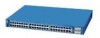
... resources, use gigabit GBIC modules to connect the switches directly to a backbone switch in a GigaStack configuration, where the 1-Gbps connection is shared among the switches. If one of the switches, you can configure the stack members and the Catalyst 3508G XL switch as the Catalyst 3508G XL switch. You can connect the Catalyst 3500 XL switches, again in a star configuration, to 10 km - 1000BaseZX...
... resources, use gigabit GBIC modules to connect the switches directly to a backbone switch in a GigaStack configuration, where the 1-Gbps connection is shared among the switches. If one of the switches, you can configure the stack members and the Catalyst 3508G XL switch as the Catalyst 3508G XL switch. You can connect the Catalyst 3500 XL switches, again in a star configuration, to 10 km - 1000BaseZX...

Installation Guide
Page 60
... 49 Warning Read the installation instructions before connecting the system to the terminals. Statement 66 Catalyst 3500 Series XL Hardware Installation Guide 2-2 78-6456-04 Statement 43 Warning Do not stack the chassis on equipment that is to install or replace this equipment. Metal objects will ...heat up when connected to power and ground and can cause severe bodily injury and equipment damage. Preparing for Installation Chapter 2 Installing and Starting Up the Switch ...
... 49 Warning Read the installation instructions before connecting the system to the terminals. Statement 66 Catalyst 3500 Series XL Hardware Installation Guide 2-2 78-6456-04 Statement 43 Warning Do not stack the chassis on equipment that is to install or replace this equipment. Metal objects will ...heat up when connected to power and ground and can cause severe bodily injury and equipment damage. Preparing for Installation Chapter 2 Installing and Starting Up the Switch ...

Installation Guide
Page 121
...229;väl som skada på utrustningen uppstå. 78-6456-04 Catalyst 3500 Series XL Hardware Installation Guide C-13 Als het chassis mocht vallen, kan dit ernstig lichamelijk letsel en beschadiging van de apparatuur veroorzaken. Asennuspohja voi pudotessaan aiheuttaa vaikean ruumiinvamman tai ...225; causar ferimentos graves e danos no equipamento. ¡Atención! Appendix C Translated Safety Warnings Stacking the Chassis Warning Stacking the Chassis Warning Warning Do not stack the chassis on any other equipment. If the chassis falls, it can cause severe bodily injury and ...
...229;väl som skada på utrustningen uppstå. 78-6456-04 Catalyst 3500 Series XL Hardware Installation Guide C-13 Als het chassis mocht vallen, kan dit ernstig lichamelijk letsel en beschadiging van de apparatuur veroorzaken. Asennuspohja voi pudotessaan aiheuttaa vaikean ruumiinvamman tai ...225; causar ferimentos graves e danos no equipamento. ¡Atención! Appendix C Translated Safety Warnings Stacking the Chassis Warning Stacking the Chassis Warning Warning Do not stack the chassis on any other equipment. If the chassis falls, it can cause severe bodily injury and ...

Installation Guide
Page 122
Stacking the Chassis Warning Appendix C Translated Safety Warnings C-14 Catalyst 3500 Series XL Hardware Installation Guide 78-6456-04
Stacking the Chassis Warning Appendix C Translated Safety Warnings C-14 Catalyst 3500 Series XL Hardware Installation Guide 78-6456-04
Installation Guide
Page 158
...41 slots See ports 1-9 SNMP network management platforms 1-3, 1-25 software by model 1-2 software switch management 1-24 specifications A-1 stacking the chassis warning C-13 standard edition software, switches running 1-2 startup powering on 2-17 straight-through cable pinouts B-4 SunNet Manager 1-25 supply ... the CLI 1-25 temperature operating A-1 warning C-16 terminal, connecting to switch 2-23 terminal emulation software 2-23 TN power warning C-19 translated warnings C-1 troubleshooting 3-1 to 3-5 U UTL LED 1-16, 1-17 IN-6 Catalyst 3500 Series XL Hardware Installation Guide 78-6456-04
...41 slots See ports 1-9 SNMP network management platforms 1-3, 1-25 software by model 1-2 software switch management 1-24 specifications A-1 stacking the chassis warning C-13 standard edition software, switches running 1-2 startup powering on 2-17 straight-through cable pinouts B-4 SunNet Manager 1-25 supply ... the CLI 1-25 temperature operating A-1 warning C-16 terminal, connecting to switch 2-23 terminal emulation software 2-23 TN power warning C-19 translated warnings C-1 troubleshooting 3-1 to 3-5 U UTL LED 1-16, 1-17 IN-6 Catalyst 3500 Series XL Hardware Installation Guide 78-6456-04