
Hardware Installation Guide
Page 13
...do not have a redundant power system (RPS) connector for an optional Cisco RPS 2300 or Cisco RPS 675 redundant power system that operates on AC input and supplies backup DC power to the switch. See the compatibility matrix documents for the RPS systems on Cisco.com for the RPS...modules. Chapter 1 Product Overview Features These are supported on specific switches, see the Cisco Gigabit Ethernet Transceiver Modules Compatibility Matrix at this Cisco.com URL: http://www.cisco.com/en/US/docs/interfaces_modules/transceiver_modules/compatibility/matrix/ OL_6981.html The 1000BASE-T SFP modules ...
...do not have a redundant power system (RPS) connector for an optional Cisco RPS 2300 or Cisco RPS 675 redundant power system that operates on AC input and supplies backup DC power to the switch. See the compatibility matrix documents for the RPS systems on Cisco.com for the RPS...modules. Chapter 1 Product Overview Features These are supported on specific switches, see the Cisco Gigabit Ethernet Transceiver Modules Compatibility Matrix at this Cisco.com URL: http://www.cisco.com/en/US/docs/interfaces_modules/transceiver_modules/compatibility/matrix/ OL_6981.html The 1000BASE-T SFP modules ...

Hardware Installation Guide
Page 26
... 2960-24TC-S, 2960-48TC-S, and 2960-48TT-S switches do not have failed. The RPS is providing power to another device (redundancy has been allocated to a neighboring device). Contact Cisco Systems. The internal power supply in a switch has failed, and the RPS is the default mode. The port operating speed: 10...100 Mb/s in a fault condition. The PoE LED is off or not properly connected. This is providing power to the switch (redundancy has been allocated to provide back-up power, if required. Front Panel Description Chapter 1 Product Overview RPS LED The RPS LED shows the RPS status....
... 2960-24TC-S, 2960-48TC-S, and 2960-48TT-S switches do not have failed. The RPS is providing power to another device (redundancy has been allocated to a neighboring device). Contact Cisco Systems. The internal power supply in a switch has failed, and the RPS is the default mode. The port operating speed: 10...100 Mb/s in a fault condition. The PoE LED is off or not properly connected. This is providing power to the switch (redundancy has been allocated to provide back-up power, if required. Front Panel Description Chapter 1 Product Overview RPS LED The RPS LED shows the RPS status....
Hardware Installation Guide
Page 30
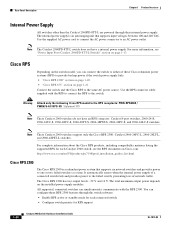
.... It automatically senses when the internal power supply of a connected switch fails and provides power to an AC power outlet. You can configure these Cisco redundant power systems (RPS) to provide backup power if the switch power supply fails: • "Cisco RPS 2300" section on page 1-20 • "Cisco RPS 675" section on Cisco.com: http://www.cisco.com/en/US/products/ps7148/prod_installation_guides_list...
.... It automatically senses when the internal power supply of a connected switch fails and provides power to an AC power outlet. You can configure these Cisco redundant power systems (RPS) to provide backup power if the switch power supply fails: • "Cisco RPS 2300" section on page 1-20 • "Cisco RPS 675" section on Cisco.com: http://www.cisco.com/en/US/products/ps7148/prod_installation_guides_list...

Hardware Installation Guide
Page 31
... when the internal power supply of a connected switch fails and provides power to -DB-25 female DTE adapter. Note The console port on the Catalyst 2960 8-port switches is a redundant power system that supports six network devices and provides power to one failed switch at a time. The Cisco RPS 675 has two...can connect the switch to a PC by the RPS • Obtain status reports for the RPS power-supply module • Read and monitor backup, failure, and exception history Cisco RPS 675 The Cisco 675 RPS is on the front panel rather than on a left and right side panels. Chapter 1...
... when the internal power supply of a connected switch fails and provides power to -DB-25 female DTE adapter. Note The console port on the Catalyst 2960 8-port switches is a redundant power system that supports six network devices and provides power to one failed switch at a time. The Cisco RPS 675 has two...can connect the switch to a PC by the RPS • Obtain status reports for the RPS power-supply module • Read and monitor backup, failure, and exception history Cisco RPS 675 The Cisco 675 RPS is on the front panel rather than on a left and right side panels. Chapter 1...
Hardware Installation Guide
Page 45
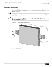
...firmly attached plywood mounting backboard. Mount the switch with the front panel facing up , as shown in Figure 2-12. Statement 266 Warning If a redundant power system (RPS) is attached securely to wall studs or to the switch, install an RPS connector cover on a Wall 11X 12X 11X 1X 12X... 11X 1X 12X 1X 1X 11X 1X 12X MODE STASCPKEDEUDPSLTXAMTASRTPRSSYST 1 1 1 User-supplied screws 204621 OL-7075-09 Catalyst 2960 Switch Hardware Installation Guide 2-13 Statement 265 Figure 2-12 Mounting the Switch on the back of the switch...
...firmly attached plywood mounting backboard. Mount the switch with the front panel facing up , as shown in Figure 2-12. Statement 266 Warning If a redundant power system (RPS) is attached securely to wall studs or to the switch, install an RPS connector cover on a Wall 11X 12X 11X 1X 12X... 11X 1X 12X 1X 1X 11X 1X 12X MODE STASCPKEDEUDPSLTXAMTASRTPRSSYST 1 1 1 User-supplied screws 204621 OL-7075-09 Catalyst 2960 Switch Hardware Installation Guide 2-13 Statement 265 Figure 2-12 Mounting the Switch on the back of the switch...

Hardware Installation Guide
Page 98
...parity • None (flow control) Connecting to a Power Source Follow these steps to connect to a power source: Step 1 Step 2 Connect one end of the supplied AC power cord to communicate with your RPS. See Figure C-1. Call Cisco technical support representative if your switch, the PC or ...Switch Hardware Installation Guide C-4 OL-7075-09 Note If you powered on a switch rear panel. When the POST completes successfully, the System LED remains green. POST failures are connecting the switch to a Cisco redundant power system (RPS), refer to display the setup program prompt....
...parity • None (flow control) Connecting to a Power Source Follow these steps to connect to a power source: Step 1 Step 2 Connect one end of the supplied AC power cord to communicate with your RPS. See Figure C-1. Call Cisco technical support representative if your switch, the PC or ...Switch Hardware Installation Guide C-4 OL-7075-09 Note If you powered on a switch rear panel. When the POST completes successfully, the System LED remains green. POST failures are connecting the switch to a Cisco redundant power system (RPS), refer to display the setup program prompt....
Hardware Installation Guide
Page 106
...-mounting 2-7 to 2-10, 3-15 to 3-16 rack-mounting warning 2-3, 2-6, 3-2, 3-15 read the wall-mounting instructions warning 2-2, 3-11, 3-17 rear panel clearance 2-5, 3-4 description 1-19 to 1-21 redundant power supply See RPS removing SFP modules 2-17 to 2-18 restricted access area warning 2-3 RJ-45 connector, console port B-4 RJ-45 console port 1-19 RPS attachment warning...
...-mounting 2-7 to 2-10, 3-15 to 3-16 rack-mounting warning 2-3, 2-6, 3-2, 3-15 read the wall-mounting instructions warning 2-2, 3-11, 3-17 rear panel clearance 2-5, 3-4 description 1-19 to 1-21 redundant power supply See RPS removing SFP modules 2-17 to 2-18 restricted access area warning 2-3 RJ-45 connector, console port B-4 RJ-45 console port 1-19 RPS attachment warning...


