
Quick Start Guide
Page 2
...-24, and SG 102-24 switches support frames up to other devices. Jumbo Frame support improves network throughput and reduces CPU utilization during heavy loads voice and video traffic are examined for the cable type (straight-through or crossover) used to connect the unmanaged rackmount switch to 9,000 bytes called jumbo frames. Network speed auto-negotiation automatically selects the best connection speed and mode (half- or full-duplex) for...
...-24, and SG 102-24 switches support frames up to other devices. Jumbo Frame support improves network throughput and reduces CPU utilization during heavy loads voice and video traffic are examined for the cable type (straight-through or crossover) used to connect the unmanaged rackmount switch to 9,000 bytes called jumbo frames. Network speed auto-negotiation automatically selects the best connection speed and mode (half- or full-duplex) for...
Quick Start Guide
Page 7
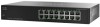
... Panel LEDs System LED-Lights green when the switch is powered on the front panel of the unmanaged rackmount switches that provide non-blocking, wire-speed switching for wired network communications. The auto-sensing, Ethernet (802.3) ports are connection points for miniGBIC modules, so the unmanaged rackmount switch can uplink to the miniGBIC interface traffic. Flashes when the port is detected. 276579 3 Features of the Unmanaged Rackmount Switch This section describes the exterior of the switch...
... Panel LEDs System LED-Lights green when the switch is powered on the front panel of the unmanaged rackmount switches that provide non-blocking, wire-speed switching for wired network communications. The auto-sensing, Ethernet (802.3) ports are connection points for miniGBIC modules, so the unmanaged rackmount switch can uplink to the miniGBIC interface traffic. Flashes when the port is detected. 276579 3 Features of the Unmanaged Rackmount Switch This section describes the exterior of the switch...
Quick Start Guide
Page 8
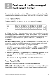
... when another device is connected to the port, is powered on , and a 1000 Mbps link is established between the devices. When the LED is off , the connection speed is under 100 Mbps or nothing is cabled to the port. Back Panel The power port is located on the side panel of the unmanaged rackmount switch. MiniGBIC (if present)-Lights green when a connection is active. It flashes green when the connection is made...
... when another device is connected to the port, is powered on , and a 1000 Mbps link is established between the devices. When the LED is off , the connection speed is under 100 Mbps or nothing is cabled to the port. Back Panel The power port is located on the side panel of the unmanaged rackmount switch. MiniGBIC (if present)-Lights green when a connection is active. It flashes green when the connection is made...
Hardware Installation Guide
Page 2
... BY THIS REFERENCE. Any examples, command display output, and figures included in accordance with radio and television reception. THE SPECIFICATIONS AND INFORMATION REGARDING THE PRODUCTS IN THIS MANUAL ARE SUBJECT TO CHANGE WITHOUT NOTICE. CCDE, CCENT, Cisco Yes, Cisco Stadium Vision, the Cisco logo, DCE, and Welcome to Increase Your Internet Quotient, Transpose, Webbed, and the Webbed logo are trademarks; and Access Registrar...
... BY THIS REFERENCE. Any examples, command display output, and figures included in accordance with radio and television reception. THE SPECIFICATIONS AND INFORMATION REGARDING THE PRODUCTS IN THIS MANUAL ARE SUBJECT TO CHANGE WITHOUT NOTICE. CCDE, CCENT, Cisco Yes, Cisco Stadium Vision, the Cisco logo, DCE, and Welcome to Increase Your Internet Quotient, Transpose, Webbed, and the Webbed logo are trademarks; and Access Registrar...

Hardware Installation Guide
Page 8
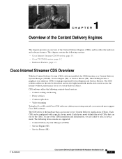
... Notes for the Cisco Internet Streamer CDS 2.0 • Release Notes for the Cisco Internet Streamer CDS 2.1 • Cisco Internet Streamer CDS 2.0-2.1 Software Configuration Guide • Cisco Internet Streamer CDS 2.0-2.1 Quick Start Guide • Cisco Internet Streamer CDS 2.0-2.1 API Guide • Cisco Content Delivery System 2.x Documentation Roadmap • Regulatory Compliance and Safety Information for connecting DC power to install a CDE, and provides troubleshooting information. Objectives This guide documents the hardware features of the Cisco Content Delivery System...
... Notes for the Cisco Internet Streamer CDS 2.0 • Release Notes for the Cisco Internet Streamer CDS 2.1 • Cisco Internet Streamer CDS 2.0-2.1 Software Configuration Guide • Cisco Internet Streamer CDS 2.0-2.1 Quick Start Guide • Cisco Internet Streamer CDS 2.0-2.1 API Guide • Cisco Content Delivery System 2.x Documentation Roadmap • Regulatory Compliance and Safety Information for connecting DC power to install a CDE, and provides troubleshooting information. Objectives This guide documents the hardware features of the Cisco Content Delivery System...
Hardware Installation Guide
Page 17
... CDE can be configured with Cisco CDS software within your existing network, your network must support Cisco IOS software. CDS software offers the following content-based services: • Content caching and hosting • Proxy services • Content replication • Video streaming To deploy Cisco SEs with a specific device mode. The CDSM provides a graphical user interface (GUI) to distribute and receive high-bandwidth, media-rich content across the Internet without performance...
... CDE can be configured with Cisco CDS software within your existing network, your network must support Cisco IOS software. CDS software offers the following content-based services: • Content caching and hosting • Proxy services • Content replication • Video streaming To deploy Cisco SEs with a specific device mode. The CDSM provides a graphical user interface (GUI) to distribute and receive high-bandwidth, media-rich content across the Internet without performance...

Hardware Installation Guide
Page 18
... servers • Linux operating system • OnDemand software • Video Accelerator software OnDemand Application In order for cable operators to successfully deliver Video On Demand (VOD) services, a number of caching across Gigabit Ethernet networks. The CDSM is responsible for ingest, storage, content distribution, personalization and streaming of one or more CDE300s. The CDE200 supports device-mode configuration and can be configured with the CDS 2.0-2.1 software...
... servers • Linux operating system • OnDemand software • Video Accelerator software OnDemand Application In order for cable operators to successfully deliver Video On Demand (VOD) services, a number of caching across Gigabit Ethernet networks. The CDSM is responsible for ingest, storage, content distribution, personalization and streaming of one or more CDE300s. The CDE200 supports device-mode configuration and can be configured with the CDS 2.0-2.1 software...
Hardware Installation Guide
Page 22
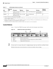
.../200/300/400 Hardware Installation Guide 1-6 OL-13478-03 Figure 1-9 CDE100 Front Panel Control Buttons 1 2 3 211766 1 Power 2 Reset 3 CD eject Powers up to 2400 hours of standard definition content (3840 hours on self-test (POST). The Reset button does not restore the device to 24 SATA hard - 84 drives3 1. Hardware Features Chapter 1 Overview of storage. Provides management communication with 12 full-duplex Gigabit Ethernet (GE) interfaces, each used to deliver up...
.../200/300/400 Hardware Installation Guide 1-6 OL-13478-03 Figure 1-9 CDE100 Front Panel Control Buttons 1 2 3 211766 1 Power 2 Reset 3 CD eject Powers up to 2400 hours of standard definition content (3840 hours on self-test (POST). The Reset button does not restore the device to 24 SATA hard - 84 drives3 1. Hardware Features Chapter 1 Overview of storage. Provides management communication with 12 full-duplex Gigabit Ethernet (GE) interfaces, each used to deliver up...
Hardware Installation Guide
Page 27
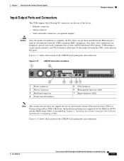
... panel ports and connectors. However, the keyboard and mouse are only used to maintain EMC compliance. All PS/2 keyboard, PS/2 mouse, USB interface, serial console interface, and VGA interface cables must be disconnected from the CDE's front and rear I /O cables, except those installed in Chapter 4, "Installing the Internet Streamer CDS Software and Initially Configuring a CDE." OL-13478-03 Cisco Content Delivery Engine 100/200/300/400 Hardware Installation Guide...
... panel ports and connectors. However, the keyboard and mouse are only used to maintain EMC compliance. All PS/2 keyboard, PS/2 mouse, USB interface, serial console interface, and VGA interface cables must be disconnected from the CDE's front and rear I /O cables, except those installed in Chapter 4, "Installing the Internet Streamer CDS Software and Initially Configuring a CDE." OL-13478-03 Cisco Content Delivery Engine 100/200/300/400 Hardware Installation Guide...

Hardware Installation Guide
Page 36
... service technician. • If any Cisco product except as part of the following general precautions for using and working with your system documentation. Install only in this section. Do not service any of the building installation. The product has been dropped or damaged. - Warning This unit might have more than one power supply connection. Components inside these compartments should be removed to a grounded power...
... service technician. • If any Cisco product except as part of the following general precautions for using and working with your system documentation. Install only in this section. Do not service any of the building installation. The product has been dropped or damaged. - Warning This unit might have more than one power supply connection. Components inside these compartments should be removed to a grounded power...
Hardware Installation Guide
Page 42
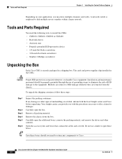
... to return any damage or other contents. Cisco Content Delivery Engine 100/200/300/400 Hardware Installation Guide 3-2 OL-13478-03 A network switch is securely packaged in the CDEs. Open the accessory kits and boxes that contain the cables and so forth. Tools and Parts Required You need to eliminate the risk of mishandling are removed from the box. Remove the chassis from the...
... to return any damage or other contents. Cisco Content Delivery Engine 100/200/300/400 Hardware Installation Guide 3-2 OL-13478-03 A network switch is securely packaged in the CDEs. Open the accessory kits and boxes that contain the cables and so forth. Tools and Parts Required You need to eliminate the risk of mishandling are removed from the box. Remove the chassis from the...

Hardware Installation Guide
Page 44
... place any air vents; Set all dip switches at the same time. • Remove the rack doors and side panels to provide easier access during installation. • Connect the device to the secondary IDE cable. b. There are two IDE connectors on the chassis by performing the following steps: Step 1 Remove the top cover on the motherboard. Disable the onboard SCSI controller by connect pins 2 and 3 (instead of...
... place any air vents; Set all dip switches at the same time. • Remove the rack doors and side panels to provide easier access during installation. • Connect the device to the secondary IDE cable. b. There are two IDE connectors on the chassis by performing the following steps: Step 1 Remove the top cover on the motherboard. Disable the onboard SCSI controller by connect pins 2 and 3 (instead of...

Hardware Installation Guide
Page 45
.../en/US/docs/video/cds/cde/cde110/installation/guide/ch3_inst.html#wp1051129 Note The CDE300 and CDE400 ship with numerous standard USB and Ethernet ports. Making Physical Connections After mounting the servers, continue the hardware setup by 30-inch deep rack. Any other cable connections are temporary and are required to the Telecommunication Network System only through a device that a hazardous condition is intended for...
.../en/US/docs/video/cds/cde/cde110/installation/guide/ch3_inst.html#wp1051129 Note The CDE300 and CDE400 ship with numerous standard USB and Ethernet ports. Making Physical Connections After mounting the servers, continue the hardware setup by 30-inch deep rack. Any other cable connections are temporary and are required to the Telecommunication Network System only through a device that a hazardous condition is intended for...
Hardware Installation Guide
Page 60
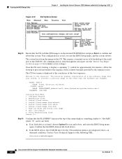
... a remote terminal provided by the terminal server. Contact Cisco Technical Support at the conclusion of the CDE100. All communication is displayed at the following URL: www.cisco.com/techsupport Cisco Content Delivery Engine 100/200/300/400 Hardware Installation Guide 4-8 OL-13478-03 Once the CD starts booting, it displays a spinning "|" symbol for terminal server settings). Install flash image from cdrom 6. Install flash image from network 5. Exit (and reboot...
... a remote terminal provided by the terminal server. Contact Cisco Technical Support at the conclusion of the CDE100. All communication is displayed at the following URL: www.cisco.com/techsupport Cisco Content Delivery Engine 100/200/300/400 Hardware Installation Guide 4-8 OL-13478-03 Once the CD starts booting, it displays a spinning "|" symbol for terminal server settings). Install flash image from cdrom 6. Install flash image from network 5. Exit (and reboot...
Hardware Installation Guide
Page 67
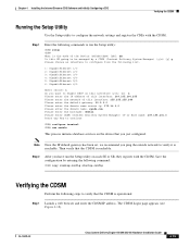
.../200/300/400 Hardware Installation Guide 4-15 Chapter 4 Installing the Internet Streamer CDS Software and Initially Configuring a CDE Verifying the CDSM Running the Setup Utility Use the Setup utility to configure the network settings and register the CDEs with the CDSM. Note Once the IP default gateway has been set, we recommend you have run the Setup utility: CDE# setup CDE# What is the mode of this interface: 255.255...
.../200/300/400 Hardware Installation Guide 4-15 Chapter 4 Installing the Internet Streamer CDS Software and Initially Configuring a CDE Verifying the CDSM Running the Setup Utility Use the Setup utility to configure the network settings and register the CDEs with the CDSM. Note Once the IP default gateway has been set, we recommend you have run the Setup utility: CDE# setup CDE# What is the mode of this interface: 255.255...
Hardware Installation Guide
Page 71
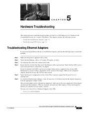
...-13478-03 Cisco Content Delivery Engine 100/200/300/400 Hardware Installation Guide 5-1 Driver and diagnostic utilities are having problems with a known good cable. LEDs on the version of your Ethernet adapters, perform the following sections: • Troubleshooting Ethernet Adapters, page 5-1 • Troubleshooting SATA Drives, page 5-2 Troubleshooting Ethernet Adapters If you are available on the switch. The on an adapter when power is a Broadcom component. Do not be set to download and run...
...-13478-03 Cisco Content Delivery Engine 100/200/300/400 Hardware Installation Guide 5-1 Driver and diagnostic utilities are having problems with a known good cable. LEDs on the version of your Ethernet adapters, perform the following sections: • Troubleshooting Ethernet Adapters, page 5-1 • Troubleshooting SATA Drives, page 5-2 Troubleshooting Ethernet Adapters If you are available on the switch. The on an adapter when power is a Broadcom component. Do not be set to download and run...

Hardware Installation Guide
Page 72
... of the chassis (see the "Installing or Removing Disk Drives" section on page 3-10). The SATA controller cards are located in the system. Troubleshooting SATA Drives Chapter 5 Hardware Troubleshooting Troubleshooting SATA Drives The CDE200 and CDE400 contain SATA drives. If the problem still persists, contact Cisco Technical Support at the following steps: Step 1 Step 2 Step 3 Reboot the system. If the problem persists, replace the drive...
... of the chassis (see the "Installing or Removing Disk Drives" section on page 3-10). The SATA controller cards are located in the system. Troubleshooting SATA Drives Chapter 5 Hardware Troubleshooting Troubleshooting SATA Drives The CDE200 and CDE400 contain SATA drives. If the problem still persists, contact Cisco Technical Support at the following steps: Step 1 Step 2 Step 3 Reboot the system. If the problem persists, replace the drive...
Hardware Installation Guide
Page 75
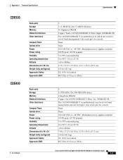
... Two 10/100/1000BASE-T on motherboard, one for out-of -band management; One serial port for console None None 100-240 VAC or -48 VDC; Appendix A Technical Specifications Specifications CDE300 CDE400 Rack units Storage Memory Network interfaces Other interfaces Compact Flash Optical drive Power Power rating Humidity Operating temperature Altitude Dimensions (H x W x D) Weight (fully configured) Approvals: Safety Approvals: EMC 3 1.15-TB SCSI (16x 73-GB SCSI...
... Two 10/100/1000BASE-T on motherboard, one for out-of -band management; One serial port for console None None 100-240 VAC or -48 VDC; Appendix A Technical Specifications Specifications CDE300 CDE400 Rack units Storage Memory Network interfaces Other interfaces Compact Flash Optical drive Power Power rating Humidity Operating temperature Altitude Dimensions (H x W x D) Weight (fully configured) Approvals: Safety Approvals: EMC 3 1.15-TB SCSI (16x 73-GB SCSI...

Hardware Installation Guide
Page 103
... 4-1, 4-14 intended uses 2-8 overview 1-1 preparing to install 2-1 registering with CDSM 4-15 safety 2-8 server types 3-1 site requirements 2-1 CDE100 BIOS Setup 4-3 connectors 1-11, 3-6 control buttons 1-6 disk drives 3-9 hardware features 1-5 LEDs 1-8 overview 1-3 physical dimensions 2-2 safety 2-6 safety warnings 2-3 specifications A-2 CDE200 BIOS Setup 4-9 configuring ports 4-2 connecting DC power D-2 connectors 1-12, 3-6 control buttons 1-7 disk drives 3-9 front cover 1-9, 3-11 hardware features 1-5 LEDs 1-9 Cisco Content Delivery Engine 100/200/300/400 Hardware Installation Guide IN-1
... 4-1, 4-14 intended uses 2-8 overview 1-1 preparing to install 2-1 registering with CDSM 4-15 safety 2-8 server types 3-1 site requirements 2-1 CDE100 BIOS Setup 4-3 connectors 1-11, 3-6 control buttons 1-6 disk drives 3-9 hardware features 1-5 LEDs 1-8 overview 1-3 physical dimensions 2-2 safety 2-6 safety warnings 2-3 specifications A-2 CDE200 BIOS Setup 4-9 configuring ports 4-2 connecting DC power D-2 connectors 1-12, 3-6 control buttons 1-7 disk drives 3-9 front cover 1-9, 3-11 hardware features 1-5 LEDs 1-9 Cisco Content Delivery Engine 100/200/300/400 Hardware Installation Guide IN-1

Hardware Installation Guide
Page 106
... 3-5 preparing CDEs for rack 3-4 rack 3-5 rack safety guidelines 3-3 software installation order 4-2 tools and parts 3-2 Integrated Vault Streamer, see ISV interfaces stream 4-2 Internet Streamer CDS overview 1-1 server types 3-1 ISV 3-1 CDE200 ISV 1-2 connections 3-9 L LEDs CDE100 1-8 CDE200 1-9 CDE300 1-10 CDE400 1-10 Lindenhurst chipset 3-1 connector pin assignments B-1 M management interface 1-11 specifications A-4 N network cables 3-8 O overcurrent protection AC circuits 2-9 DC circuits 2-9 IN-4 Cisco Content Delivery Engine 100/200/300/400 Hardware Installation Guide OL-13478-03
... 3-5 preparing CDEs for rack 3-4 rack 3-5 rack safety guidelines 3-3 software installation order 4-2 tools and parts 3-2 Integrated Vault Streamer, see ISV interfaces stream 4-2 Internet Streamer CDS overview 1-1 server types 3-1 ISV 3-1 CDE200 ISV 1-2 connections 3-9 L LEDs CDE100 1-8 CDE200 1-9 CDE300 1-10 CDE400 1-10 Lindenhurst chipset 3-1 connector pin assignments B-1 M management interface 1-11 specifications A-4 N network cables 3-8 O overcurrent protection AC circuits 2-9 DC circuits 2-9 IN-4 Cisco Content Delivery Engine 100/200/300/400 Hardware Installation Guide OL-13478-03


