
Hardware Installation Guide
Page 5
...X INDEX Technical Specifications A-1 Specifications A-1 CDE100 A-2 CDE200 A-2 CDE300 A-3 CDE400 A-3 Management A-4 Connector Pin Assignments B-1 Serial Console Interface Connector Pin Assignments B-1 Serial Port Connector B-2 Ethernet Connector Pin Assignments B-2 Ethernet Port Connector B-3 Cable Pin Assignments B-4 CDEs with Serverworks Chipset C-1 Specifications C-1 CDE100 C-1 CDE200 C-2 CDE200 (IBM) C-3 CDE300 C-3 CDE400 C-4 Connector Pin Assignments ...10 DC Power Cable Connector and Pinouts D-11 Contents OL-13478-03 Cisco Content Delivery Engine 100/200/300/400 Hardware Installation Guide...
...X INDEX Technical Specifications A-1 Specifications A-1 CDE100 A-2 CDE200 A-2 CDE300 A-3 CDE400 A-3 Management A-4 Connector Pin Assignments B-1 Serial Console Interface Connector Pin Assignments B-1 Serial Port Connector B-2 Ethernet Connector Pin Assignments B-2 Ethernet Port Connector B-3 Cable Pin Assignments B-4 CDEs with Serverworks Chipset C-1 Specifications C-1 CDE100 C-1 CDE200 C-2 CDE200 (IBM) C-3 CDE300 C-3 CDE400 C-4 Connector Pin Assignments ...10 DC Power Cable Connector and Pinouts D-11 Contents OL-13478-03 Cisco Content Delivery Engine 100/200/300/400 Hardware Installation Guide...

Hardware Installation Guide
Page 26
... power Blue 2 Hard disk drive activity Blue 3 Hard disk drive activity Blue 4 Ethernet port 1 Blue 5 Ethernet port 2 Blue 6 Power Blue State On On On On On On Description Power is connected. Port is flowing to the device. LED Color 1 Hard disk drive power Blue 2 Hard disk... their functions. Figure 1-16 CDE400 Front Panel LEDs 12 270626 270627 No. A hard disk drive is flowing to the drive. Port is in use . 1-10 Cisco Content Delivery Engine 100/200/300/400 Hardware Installation Guide OL-13478-03 Figure 1-15 CDE300 Front Panel LEDs 1 2 3 4 56 7 No. ...
... power Blue 2 Hard disk drive activity Blue 3 Hard disk drive activity Blue 4 Ethernet port 1 Blue 5 Ethernet port 2 Blue 6 Power Blue State On On On On On On Description Power is connected. Port is flowing to the device. LED Color 1 Hard disk drive power Blue 2 Hard disk... their functions. Figure 1-16 CDE400 Front Panel LEDs 12 270626 270627 No. A hard disk drive is flowing to the drive. Port is in use . 1-10 Cisco Content Delivery Engine 100/200/300/400 Hardware Installation Guide OL-13478-03 Figure 1-15 CDE300 Front Panel LEDs 1 2 3 4 56 7 No. ...

Hardware Installation Guide
Page 33
... circuits. Warning Read the installation instructions before unplugging the main power connector and/or 2) while the housing is open apertures. Statement 10 Warning The ports labeled "Ethernet," "10BaseT," "Token Ring," "Console," and "AUX" are translated into open . SELV circuits should be emitted ...from the aperture of security, and is intended for the Cisco Content Delivery Engine 100/200/300/400 document that is connected, avoid exposure...
... circuits. Warning Read the installation instructions before unplugging the main power connector and/or 2) while the housing is open apertures. Statement 10 Warning The ports labeled "Ethernet," "10BaseT," "Token Ring," "Console," and "AUX" are translated into open . SELV circuits should be emitted ...from the aperture of security, and is intended for the Cisco Content Delivery Engine 100/200/300/400 document that is connected, avoid exposure...
Hardware Installation Guide
Page 59
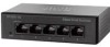
...Serial Port2 Address option to Disabled. c. OL-13478-03 Cisco Content Delivery Engine 100/200/300/400 Hardware Installation Guide 4-7 The Configure Remote Access Type and Parameters screen appears (see Figure 4-10). Set the Redirection After BIOS POST option to Disabled. ...Press OK when prompted (see Figure 4-9). Set the Serial Port Mode option to COM 1. Set the Serial port...
...Serial Port2 Address option to Disabled. c. OL-13478-03 Cisco Content Delivery Engine 100/200/300/400 Hardware Installation Guide 4-7 The Configure Remote Access Type and Parameters screen appears (see Figure 4-10). Set the Redirection After BIOS POST option to Disabled. ...Press OK when prompted (see Figure 4-9). Set the Serial Port Mode option to COM 1. Set the Serial port...
Hardware Installation Guide
Page 60
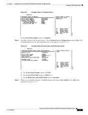
...port of the menu displays something similar to "/dev/hdX", where "X" can be any letter. Configure Network 2. Manufacture flash 3. Wipe out disks and install.bin image 8. a. b. The CD boot menu is displayed at the following URL: www.cisco.com/techsupport Cisco Content Delivery Engine 100... Main Menu: 1. Running the BIOS Setup Utility Chapter 4 Installing the Internet Streamer CDS Software and Initially Configuring a CDE Figure 4-10 Exit Options Screen Step 15 Ensure that the hardware was changed. Your configuration is not displayed, this boot sequence: Welcome to exit...
...port of the menu displays something similar to "/dev/hdX", where "X" can be any letter. Configure Network 2. Manufacture flash 3. Wipe out disks and install.bin image 8. a. b. The CD boot menu is displayed at the following URL: www.cisco.com/techsupport Cisco Content Delivery Engine 100... Main Menu: 1. Running the BIOS Setup Utility Chapter 4 Installing the Internet Streamer CDS Software and Initially Configuring a CDE Figure 4-10 Exit Options Screen Step 15 Ensure that the hardware was changed. Your configuration is not displayed, this boot sequence: Welcome to exit...
Hardware Installation Guide
Page 74
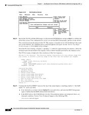
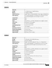
...Operating temperature Altitude Dimensions (H x W x D) Weight (fully configured) Approvals: Safety Approvals: EMC 1 290-GB SCSI (4x 73-GB SCSI disks) 4 Gigabytes DRAM Two 10/100/1000BASE-T (Copper) One serial port for console 128MB None 115-240 VAC or -48 VDC; Redundant power supplies included 500 W 5 to 95% noncondensing 0 to 50°C (32 to... 1.75 x 19 x 27.6 in . (8.90 x 44.45 x 72.39 cm) 53.5 lb (24.27 kg) UL 1950, 3rd edition FCC Part 15 Class A (USA) Cisco Content Delivery Engine 100/200/300/400 Hardware Installation Guide A-2 OL-13478-03 One serial port for console 128MB CD/DVD-ROM...
...Operating temperature Altitude Dimensions (H x W x D) Weight (fully configured) Approvals: Safety Approvals: EMC 1 290-GB SCSI (4x 73-GB SCSI disks) 4 Gigabytes DRAM Two 10/100/1000BASE-T (Copper) One serial port for console 128MB None 115-240 VAC or -48 VDC; Redundant power supplies included 500 W 5 to 95% noncondensing 0 to 50°C (32 to... 1.75 x 19 x 27.6 in . (8.90 x 44.45 x 72.39 cm) 53.5 lb (24.27 kg) UL 1950, 3rd edition FCC Part 15 Class A (USA) Cisco Content Delivery Engine 100/200/300/400 Hardware Installation Guide A-2 OL-13478-03 One serial port for console 128MB CD/DVD-ROM...
Hardware Installation Guide
Page 75
... in . (17.8 x 43.8 x 67.3 cm) 150 lb (68.0 kg) UL 1950, 3rd edition FCC Part 15 Class A (USA) OL-13478-03 Cisco Content Delivery Engine 100/200/300/400 Hardware Installation Guide A-3 Redundant power supplies included 650 W peak; 506 W nominal 5 to 90% noncondensing 0 to 50°C (32 to 122°...(24x 500-GB SATA disks) 4 Gigabytes DRAM Copper: Six 10/100/1000BASE-T; One serial port for Ingest; Fiber: Six 1000BASE-SX Two 10/100/1000BASE-T on motherboard of which one used for console None None 100-240 VAC or -48 VDC; One serial port for out-of -band management and one for out-of -...
... in . (17.8 x 43.8 x 67.3 cm) 150 lb (68.0 kg) UL 1950, 3rd edition FCC Part 15 Class A (USA) OL-13478-03 Cisco Content Delivery Engine 100/200/300/400 Hardware Installation Guide A-3 Redundant power supplies included 650 W peak; 506 W nominal 5 to 90% noncondensing 0 to 50°C (32 to 122°...(24x 500-GB SATA disks) 4 Gigabytes DRAM Copper: Six 10/100/1000BASE-T; One serial port for Ingest; Fiber: Six 1000BASE-SX Two 10/100/1000BASE-T on motherboard of which one used for console None None 100-240 VAC or -48 VDC; One serial port for out-of -band management and one for out-of -...
Hardware Installation Guide
Page 76
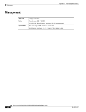
Management Appendix A Technical Specifications Management Data Rate Ports Input Cables 2 Gbps maximum Console port: DB-9 RS-232 10/100/1000 Mbps Ethernet interface: RJ-45 (management) For console port: DB-9 female serial cable For Ethernet interface: RJ-45 Category 5E or higher cable Cisco Content Delivery Engine 100/200/300/400 Hardware Installation Guide A-4 OL-13478-03
Management Appendix A Technical Specifications Management Data Rate Ports Input Cables 2 Gbps maximum Console port: DB-9 RS-232 10/100/1000 Mbps Ethernet interface: RJ-45 (management) For console port: DB-9 female serial cable For Ethernet interface: RJ-45 Category 5E or higher cable Cisco Content Delivery Engine 100/200/300/400 Hardware Installation Guide A-4 OL-13478-03

Hardware Installation Guide
Page 79
...TX/1000BASE-TX Ethernet standard requires that the cabling in the network be Category 5 or higher. OL-13478-03 Cisco Content Delivery Engine 100/200/300/400 Hardware Installation Guide B-3 This controller provides an interface for connecting to the RJ-45 connector on the... 2 3 6 1 7 8 2 4 5 Ethernet Port Connector The CDEs come with an integrated dual-port Ethernet controller. BI_DB- Unused Unused 1000BASE-T Signal BI_DC- To access the Ethernet port, connect a Category 3, 4, or 5 unshielded twisted-pair (UTP) cable to 10-Mbps, 100-Mbps, or 1000-Mbps networks and provides full-duplex (...
...TX/1000BASE-TX Ethernet standard requires that the cabling in the network be Category 5 or higher. OL-13478-03 Cisco Content Delivery Engine 100/200/300/400 Hardware Installation Guide B-3 This controller provides an interface for connecting to the RJ-45 connector on the... 2 3 6 1 7 8 2 4 5 Ethernet Port Connector The CDEs come with an integrated dual-port Ethernet controller. BI_DB- Unused Unused 1000BASE-T Signal BI_DC- To access the Ethernet port, connect a Category 3, 4, or 5 unshielded twisted-pair (UTP) cable to 10-Mbps, 100-Mbps, or 1000-Mbps networks and provides full-duplex (...

Hardware Installation Guide
Page 98
Cisco Content Delivery Engine 100/200/300/400 Hardware Installation Guide D-8 OL-13478-03 Step 1 Insert one blue DC power cable connector into the blue port on the CDE. Connecting DC Power to a CDE400 Figure D-7 CDE400 Rear Panel 9 Appendix D Connecting DC Power 10 11 280161 5 8 6 7 1 PM 4 2 PM 3 3 Building ground wire 4 PM 2 5 PM 1 6 +Return 4 32 1 7 PM...
Cisco Content Delivery Engine 100/200/300/400 Hardware Installation Guide D-8 OL-13478-03 Step 1 Insert one blue DC power cable connector into the blue port on the CDE. Connecting DC Power to a CDE400 Figure D-7 CDE400 Rear Panel 9 Appendix D Connecting DC Power 10 11 280161 5 8 6 7 1 PM 4 2 PM 3 3 Building ground wire 4 PM 2 5 PM 1 6 +Return 4 32 1 7 PM...

Hardware Installation Guide
Page 105
...CDE400 D-7 disconnect 2-9 disconnecting CDE200 D-4 CDE300 D-7 CDE400 D-10 grounding CDEs 2-9 overview D-1 PM D-1 power supply 2-9 replacing CDE200 PM D-4 CDE300 PM D-7 CDE400 PM D-10 safety warnings 2-6 devices verifying with the CDSM 4-17 disk...port cabling requirements B-3 connector 1-11 connector pin assignments B-2 connector pinout B-4 controller B-3 F FCC (Federal Communications Commission) Class A device 2-8 field-replaceable units 2-1 front cover CDE200 3-11 CDE300 3-11 CDE400 3-11 G Gigabit Ethernet connectors 4-2 ports 4-2 Gigabit Ethernet Modules A-4 Cisco Content Delivery Engine 100...
...CDE400 D-7 disconnect 2-9 disconnecting CDE200 D-4 CDE300 D-7 CDE400 D-10 grounding CDEs 2-9 overview D-1 PM D-1 power supply 2-9 replacing CDE200 PM D-4 CDE300 PM D-7 CDE400 PM D-10 safety warnings 2-6 devices verifying with the CDSM 4-17 disk...port cabling requirements B-3 connector 1-11 connector pin assignments B-2 connector pinout B-4 controller B-3 F FCC (Federal Communications Commission) Class A device 2-8 field-replaceable units 2-1 front cover CDE200 3-11 CDE300 3-11 CDE400 3-11 G Gigabit Ethernet connectors 4-2 ports 4-2 Gigabit Ethernet Modules A-4 Cisco Content Delivery Engine 100...

Hardware Installation Guide
Page 107
...console interface B-1 pin assignments, see also connector pin assignments PM CDE200 D-2, D-4 CDE300 D-5, D-7 CDE400 D-7, D-10 PM, see also power supply D-1 ports description 1-11 Gigabit Ethernet 4-2 I/O 1-11 ingest interface 1-11 management interface 1-11 serial console interface 1-11...power 2-6 DC power 2-6 SE 1-1, 3-1 connections 3-8 serial connector 1-11 ports B-2 connector pinout B-2 serial console interface 1-11, B-1 server types CDSM 1-1, 3-1 ISV 3-1 SE 1-1, 3-1 SR 1-1, 3-1 streamer 3-1 vault 3-1 OL-13478-03 Cisco Content Delivery Engine 100/200/300/400 Hardware Installation Guide IN-5
...console interface B-1 pin assignments, see also connector pin assignments PM CDE200 D-2, D-4 CDE300 D-5, D-7 CDE400 D-7, D-10 PM, see also power supply D-1 ports description 1-11 Gigabit Ethernet 4-2 I/O 1-11 ingest interface 1-11 management interface 1-11 serial console interface 1-11...power 2-6 DC power 2-6 SE 1-1, 3-1 connections 3-8 serial connector 1-11 ports B-2 connector pinout B-2 serial console interface 1-11, B-1 server types CDSM 1-1, 3-1 ISV 3-1 SE 1-1, 3-1 SR 1-1, 3-1 streamer 3-1 vault 3-1 OL-13478-03 Cisco Content Delivery Engine 100/200/300/400 Hardware Installation Guide IN-5


