
Installation Guide
Page 3
... LED 1-9 Alarm LED 1-9 Power Status LED 1-9 10/100 Port Status LEDs 1-10 100Base-FX Port Status LEDs 1-10 Dual-Purpose Port LEDs 1-11 Compact Flash Memory Card 1-11 Rear-Panel Description 1-12 Power Converter (Optional) 1-13 Management Options 1-14 Network Configurations 1-15 Switch Installation 2-1 Preparing for Installation 2-1 Warnings 2-2 Cisco IE 3000 Switch Hardware Installation Guide iii
... LED 1-9 Alarm LED 1-9 Power Status LED 1-9 10/100 Port Status LEDs 1-10 100Base-FX Port Status LEDs 1-10 Dual-Purpose Port LEDs 1-11 Compact Flash Memory Card 1-11 Rear-Panel Description 1-12 Power Converter (Optional) 1-13 Management Options 1-14 Network Configurations 1-15 Switch Installation 2-1 Preparing for Installation 2-1 Warnings 2-2 Cisco IE 3000 Switch Hardware Installation Guide iii
Installation Guide
Page 4
... 2-8 Installing or Removing the Compact Flash Memory Card 2-10 Verifying Switch Operation 2-11 Connecting a PC or a Terminal to the Console Port 2-12 Connecting the Protective Ground and DC Power 2-13 Grounding the Switch 2-13 Wiring the DC Power Source 2-16 Attach the Power ...Port 2-42 Connecting to 100BASE-FX Ports 2-43 Connecting the Switch to the Power Converter 2-44 Attaching the Power Converter to the Switch 2-45 Installing the Power Converter on a DIN Rail, Wall, or Rack Adapter 2-46 Connecting the DC Power Clip 2-46 Connecting the Power Converter to an AC Power Source 2-47 Cisco IE 3000...
... 2-8 Installing or Removing the Compact Flash Memory Card 2-10 Verifying Switch Operation 2-11 Connecting a PC or a Terminal to the Console Port 2-12 Connecting the Protective Ground and DC Power 2-13 Grounding the Switch 2-13 Wiring the DC Power Source 2-16 Attach the Power ...Port 2-42 Connecting to 100BASE-FX Ports 2-43 Connecting the Switch to the Power Converter 2-44 Attaching the Power Converter to the Switch 2-45 Installing the Power Converter on a DIN Rail, Wall, or Rack Adapter 2-46 Connecting the DC Power Clip 2-46 Connecting the Power Converter to an AC Power Source 2-47 Cisco IE 3000...
Installation Guide
Page 5
... Verify Switch POST Results 3-1 Verify Switch LEDs 3-2 Verify Switch Connections 3-2 Bad or Damaged Cable 3-2 Ethernet and Fiber Cables 3-2 Link Status 3-3 Transceiver Issues 3-3 Port and Interface Settings 3-3 Ping End Device 3-3 Spanning Tree Loops 3-4 Verify Switch Performance 3-4 Speed, Duplex, and Autonegotiation 3-4 Autonegotiation and NIC 3-4 Cabling Distance 3-5 How...European Union B-5 Installation Guidelines B-5 Environment and Enclosure Guidelines: B-5 Other Guidelines B-6 Verifying Package Contents B-7 Adding Modules to the Switch B-8 Cisco IE 3000 Switch Hardware Installation Guide v
... Verify Switch POST Results 3-1 Verify Switch LEDs 3-2 Verify Switch Connections 3-2 Bad or Damaged Cable 3-2 Ethernet and Fiber Cables 3-2 Link Status 3-3 Transceiver Issues 3-3 Port and Interface Settings 3-3 Ping End Device 3-3 Spanning Tree Loops 3-4 Verify Switch Performance 3-4 Speed, Duplex, and Autonegotiation 3-4 Autonegotiation and NIC 3-4 Cabling Distance 3-5 How...European Union B-5 Installation Guidelines B-5 Environment and Enclosure Guidelines: B-5 Other Guidelines B-6 Verifying Package Contents B-7 Adding Modules to the Switch B-8 Cisco IE 3000 Switch Hardware Installation Guide v
Installation Guide
Page 6
... the Compact Flash Memory Card B-13 Verifying Switch Operation B-14 Connecting a PC or a Terminal to the Console Port B-15 Connecting the Protective Ground and DC Power B-16 Grounding the Switch B-17 Wiring the DC Power Source B-19... Modules from SFP Module Slots B-44 Connecting to SFP Modules B-45 Connecting to a Dual-Purpose Port B-46 Connecting to 100BASE-FX Ports B-48 Connecting the Switch to the Power Converter B-49 Attaching the Power Converter to the Switch ...a DC Power Source B-57 Applying Power to the Power Converter B-59 Cisco IE 3000 Switch Hardware Installation Guide vi OL-13017-01
... the Compact Flash Memory Card B-13 Verifying Switch Operation B-14 Connecting a PC or a Terminal to the Console Port B-15 Connecting the Protective Ground and DC Power B-16 Grounding the Switch B-17 Wiring the DC Power Source B-19... Modules from SFP Module Slots B-44 Connecting to SFP Modules B-45 Connecting to a Dual-Purpose Port B-46 Connecting to 100BASE-FX Ports B-48 Connecting the Switch to the Power Converter B-49 Attaching the Power Converter to the Switch ...a DC Power Source B-57 Applying Power to the Power Converter B-59 Cisco IE 3000 Switch Hardware Installation Guide vi OL-13017-01
Installation Guide
Page 7
... a Crossover Cable C-7 Four Twisted-Pair Cable Pinouts for 1000BASE-T Ports C-7 Adapter Pinouts C-8 Configuring the Switch with the CLI-Based Setup Program D-1 Accessing the CLI from the Console Port D-1 Entering the Initial Configuration Information D-2 IP Settings D-2 Completing the Setup Program D-2 Contents OL-13017-01 Cisco IE 3000 Switch Hardware Installation Guide vii and 100BASE-TX-Compatible...
... a Crossover Cable C-7 Four Twisted-Pair Cable Pinouts for 1000BASE-T Ports C-7 Adapter Pinouts C-8 Configuring the Switch with the CLI-Based Setup Program D-1 Accessing the CLI from the Console Port D-1 Entering the Initial Configuration Information D-2 IP Settings D-2 Completing the Setup Program D-2 Contents OL-13017-01 Cisco IE 3000 Switch Hardware Installation Guide vii and 100BASE-TX-Compatible...
Installation Guide
Page 12
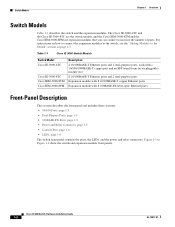
... expansion modules to the switch, see the "Adding Modules to the Switch" section on page 2-5. . Table 1-1 Cisco IE 3000 Switch Models Switch Model Cisco IE-3000-4TC Cisco IE-3000-8TC Cisco IEM-3000-8TM Cisco IEM-3000-8FM Description 4 10/100BASE-T Ethernet ports and 2 dual-purpose ports, each with a 10/100/1000BASE-T copper port and an SFP (small form-factor pluggable) module slot 8 10/100BASE-T Ethernet...
... expansion modules to the switch, see the "Adding Modules to the Switch" section on page 2-5. . Table 1-1 Cisco IE 3000 Switch Models Switch Model Cisco IE-3000-4TC Cisco IE-3000-8TC Cisco IEM-3000-8TM Cisco IEM-3000-8FM Description 4 10/100BASE-T Ethernet ports and 2 dual-purpose ports, each with a 10/100/1000BASE-T copper port and an SFP (small form-factor pluggable) module slot 8 10/100BASE-T Ethernet...
Installation Guide
Page 13
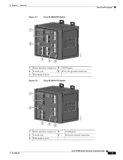
Chapter 1 Overview Figure 1-1 Cisco IE-3000-8TC Switch 1 2 Front-Panel Description 201699 3 45 1 Power and relay connectors 4 10/100 ports 2 Console port 5 Protective ground connection 3 Dual-purpose ports Figure 1-2 Cisco IE-3000-4TC Switch 1 2 201700 3 45 1 Power and relay connectors 4 2 Console port 5 3 Dual-purpose ports 10/100 ports Protective ground connection OL-13017-01 Cisco IE 3000 Switch Hardware Installation Guide 1-3
Chapter 1 Overview Figure 1-1 Cisco IE-3000-8TC Switch 1 2 Front-Panel Description 201699 3 45 1 Power and relay connectors 4 10/100 ports 2 Console port 5 Protective ground connection 3 Dual-purpose ports Figure 1-2 Cisco IE-3000-4TC Switch 1 2 201700 3 45 1 Power and relay connectors 4 2 Console port 5 3 Dual-purpose ports 10/100 ports Protective ground connection OL-13017-01 Cisco IE 3000 Switch Hardware Installation Guide 1-3
Installation Guide
Page 15
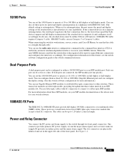
... when inserted in compliance with LC connectors to connect to other switches. These ports use Gigabit Ethernet SFP modules to establish fiber-optic connections to a fiber-optic SFP module. OL-13017-01 Cisco IE 3000 Switch Hardware Installation Guide 1-5 You can configure them as an SFP module... port. For more information about these ports for more information.) You can use a small-form-factor fixed (SFF) fiber-...
... when inserted in compliance with LC connectors to connect to other switches. These ports use Gigabit Ethernet SFP modules to establish fiber-optic connections to a fiber-optic SFP module. OL-13017-01 Cisco IE 3000 Switch Hardware Installation Guide 1-5 You can configure them as an SFP module... port. For more information about these ports for more information.) You can use a small-form-factor fixed (SFF) fiber-...
Installation Guide
Page 16
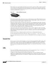
...(see Appendix C, "Cable and Connectors." For more information about the power and relay connector, see Figure 1-5). You can connect them . Cisco IE 3000 Switch Hardware Installation Guide 1-6 OL-13017-01 Both alarm terminals on page C-5. To connect an external alarm device to the relay, you can...front panel LEDs, and the following sections describe them without regard to -DB-9 adapter cable. All LEDs are visible through the console port and the supplied RJ-45-to polarity. If one or with dual power sources. Front-Panel Description Chapter 1 Overview The switch ...
...(see Appendix C, "Cable and Connectors." For more information about the power and relay connector, see Figure 1-5). You can connect them . Cisco IE 3000 Switch Hardware Installation Guide 1-6 OL-13017-01 Both alarm terminals on page C-5. To connect an external alarm device to the relay, you can...front panel LEDs, and the following sections describe them without regard to -DB-9 adapter cable. All LEDs are visible through the console port and the supplied RJ-45-to polarity. If one or with dual power sources. Front-Panel Description Chapter 1 Overview The switch ...

Installation Guide
Page 17
Chapter 1 Overview Figure 1-6 1 2 3 4 LEDs on the Cisco IE 3000 Switch Front-Panel Description 201703 5 67 8 1 Express setup button 2 System LED 3 Alarm LED 4 Setup LED 5 Dual-purpose uplink port LED 6 Pwr B LED 7 Pwr A LED 8 Port LED Figure 1-7 LEDs on the Cisco IEM-3000-8TM Module 201706 1 1 10/100 port LED OL-13017-01 Cisco IE 3000 Switch Hardware Installation Guide 1-7
Chapter 1 Overview Figure 1-6 1 2 3 4 LEDs on the Cisco IE 3000 Switch Front-Panel Description 201703 5 67 8 1 Express setup button 2 System LED 3 Alarm LED 4 Setup LED 5 Dual-purpose uplink port LED 6 Pwr B LED 7 Pwr A LED 8 Port LED Figure 1-7 LEDs on the Cisco IEM-3000-8TM Module 201706 1 1 10/100 port LED OL-13017-01 Cisco IE 3000 Switch Hardware Installation Guide 1-7

Installation Guide
Page 18
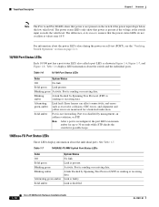
Cisco IE 3000 Switch Hardware Installation Guide 1-8 OL-13017-01 Table 1-2 Setup LED Color Off (dark) Solid green Blinking green Solid red Setup Status Switch is no available switch port to which to start initial setup or recovery because there is configured as a managed switch. Switch ...Table 1-2 lists the LED colors and their meanings. Front-Panel Description Figure 1-8 LEDs on the Cisco IEM-3000-8FM Module Chapter 1 Overview 201705 1 Setup LED 1 100BASE -FX port LEDs The Setup LED displays the express setup mode for the initial configuration. Switch is in recovery...
Cisco IE 3000 Switch Hardware Installation Guide 1-8 OL-13017-01 Table 1-2 Setup LED Color Off (dark) Solid green Blinking green Solid red Setup Status Switch is no available switch port to which to start initial setup or recovery because there is configured as a managed switch. Switch ...Table 1-2 lists the LED colors and their meanings. Front-Panel Description Figure 1-8 LEDs on the Cisco IEM-3000-8FM Module Chapter 1 Overview 201705 1 Setup LED 1 100BASE -FX port LEDs The Setup LED displays the express setup mode for the initial configuration. Switch is in recovery...
Installation Guide
Page 20
... faulty. Link is not forwarding. Link is sending or receiving data. Table 1-6 displays LED information about the individual ports. Port is disabled. 1-10 Cisco IE 3000 Switch Hardware Installation Guide OL-13017-01 Blinking amber A link blocked by Spanning Tree Protocol (STP) is sending or receiving data. Activity. A link blocked by ...
... faulty. Link is not forwarding. Link is sending or receiving data. Table 1-6 displays LED information about the individual ports. Port is disabled. 1-10 Cisco IE 3000 Switch Hardware Installation Guide OL-13017-01 Blinking amber A link blocked by Spanning Tree Protocol (STP) is sending or receiving data. Activity. A link blocked by ...
Installation Guide
Page 21
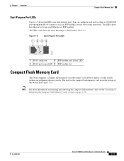
... the Compact Flash Memory Card" section on the bottom of the switch. The LEDs show how the port is on page 2-10. Figure 1-9 Dual-Purpose Port LEDs 1 234 1 203660 1 RJ-45 connector 3 SFP module port in-use LED 4 SFP module slot Compact Flash Memory Card The switch supports a compact flash memory ...time. The slot for the compact flash memory card is being used (Ethernet or SFP module). Chapter 1 Overview Compact Flash Memory Card Dual-Purpose Port LEDs Figure 1-9 shows the LEDs on a dual-purpose port. OL-13017-01 Cisco IE 3000 Switch Hardware Installation Guide 1-11
... the Compact Flash Memory Card" section on the bottom of the switch. The LEDs show how the port is on page 2-10. Figure 1-9 Dual-Purpose Port LEDs 1 234 1 203660 1 RJ-45 connector 3 SFP module port in-use LED 4 SFP module slot Compact Flash Memory Card The switch supports a compact flash memory ...time. The slot for the compact flash memory card is being used (Ethernet or SFP module). Chapter 1 Overview Compact Flash Memory Card Dual-Purpose Port LEDs Figure 1-9 shows the LEDs on a dual-purpose port. OL-13017-01 Cisco IE 3000 Switch Hardware Installation Guide 1-11
Installation Guide
Page 24
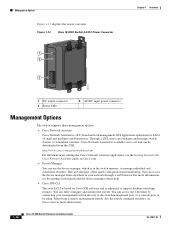
.... For more information. 1-14 Cisco IE 3000 Switch Hardware Installation Guide OL-13017-01 You can configure and manage switch clusters or standalone switches. See the switch command reference on Cisco.com for LANs of small and...Cisco IE 3000 Switch AC/DC Power Converter 1 2 3 Chapter 1 Overview 202314 1 DC output connector 2 Status LED 3 AC/DC input power connector Management Options The switch supports these management options: • Cisco Network Assistant Cisco Network Assistant is in your management station directly to the switch management port, or a console port...
.... For more information. 1-14 Cisco IE 3000 Switch Hardware Installation Guide OL-13017-01 You can configure and manage switch clusters or standalone switches. See the switch command reference on Cisco.com for LANs of small and...Cisco IE 3000 Switch AC/DC Power Converter 1 2 3 Chapter 1 Overview 202314 1 DC output connector 2 Status LED 3 AC/DC input power connector Management Options The switch supports these management options: • Cisco Network Assistant Cisco Network Assistant is in your management station directly to the switch management port, or a console port...

Installation Guide
Page 27
... • Connecting Power and Alarm Circuits, page 2-32 • Connecting Destination Ports, page 2-36 • Connecting the Switch to the Power Converter, page 2-44 • Where to other devices. Read these topics: • Warnings, page 2-2 • Installation Guidelines, page 2-3 • Verifying Package Contents, page 2-5 OL-13017-01 Cisco IE 3000 Switch Hardware Installation Guide 2-1
... • Connecting Power and Alarm Circuits, page 2-32 • Connecting Destination Ports, page 2-36 • Connecting the Switch to the Power Converter, page 2-44 • Where to other devices. Read these topics: • Warnings, page 2-2 • Installation Guidelines, page 2-3 • Verifying Package Contents, page 2-5 OL-13017-01 Cisco IE 3000 Switch Hardware Installation Guide 2-1
Installation Guide
Page 28
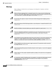
... following ports must be handled according to its power source. Never defeat the ground conductor or operate the equipment in the Regulatory Compliance and Safety Information Guide. All connections must be accessed only through an approved network termination unit with integral circuit protection. 10/100/1000 Ethernet Statement 1044 Cisco IE 3000 Switch Hardware...
... following ports must be handled according to its power source. Never defeat the ground conductor or operate the equipment in the Regulatory Compliance and Safety Information Guide. All connections must be accessed only through an approved network termination unit with integral circuit protection. 10/100/1000 Ethernet Statement 1044 Cisco IE 3000 Switch Hardware...
Installation Guide
Page 30
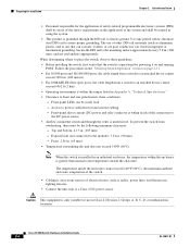
... noise, such as aluminum, plastic, and so on and running POST. Exposed side (not connected to assure proper grounding. Access to ports is within the ranges listed in Appendix A, "Technical Specifications." • Clearance to an attached device cannot exceed 6562 ft (2 km).... lighting fixtures. • Connect the unit only to the mounting surface approximately every 7.8 in. (200 mm), and use in . (90 mm) - Cisco IE 3000 Switch Hardware Installation Guide 2-4 OL-13017-01 Use zinc-plated yellow-chromate steel DIN rail to the module): 3.54 in Class I, Division 2, Groups A, ...
... noise, such as aluminum, plastic, and so on and running POST. Exposed side (not connected to assure proper grounding. Access to ports is within the ranges listed in Appendix A, "Technical Specifications." • Clearance to an attached device cannot exceed 6562 ft (2 km).... lighting fixtures. • Connect the unit only to the mounting surface approximately every 7.8 in. (200 mm), and use in . (90 mm) - Cisco IE 3000 Switch Hardware Installation Guide 2-4 OL-13017-01 Use zinc-plated yellow-chromate steel DIN rail to the module): 3.54 in Class I, Division 2, Groups A, ...
Installation Guide
Page 31
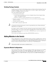
... standalone devices with four or eight Fast Ethernet ports, respectively. Regulatory Compliance and Safety Information for the Cisco IE 3000 Switch • Regulatory Compliance and Safety Information for damage. Adding Modules to the Switch The Cisco IE-3000-4TC or the Cisco IE-3000-8TC switch can connect the Cisco IEM-3000-8TM and the Cisco IEM-3000-8FM expansion modules. If you want to...
... standalone devices with four or eight Fast Ethernet ports, respectively. Regulatory Compliance and Safety Information for the Cisco IE 3000 Switch • Regulatory Compliance and Safety Information for damage. Adding Modules to the Switch The Cisco IE-3000-4TC or the Cisco IE-3000-8TC switch can connect the Cisco IEM-3000-8TM and the Cisco IEM-3000-8FM expansion modules. If you want to...
Installation Guide
Page 32
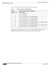
... Port Type 10/100FE 100FX 4 8 4 8 12 8 8 16 12 8 20 16 8 24 Switch and Expansion Modules Combination Cisco IE-3000-4TC 1 Cisco IE-3000-4TC 1 Cisco IE-3000-8TC 1 Cisco IE-3000-4TC and 1 Cisco IEM-3000-8FM 1 Cisco IE-3000-4TC and 1 Cisco IEM-3000-8TM 1 Cisco IE-3000-8TC and 1 Cisco IEM-3000-8FM 1 Cisco IE-3000-8TC and 1 Cisco IEM-3000-8TM 1 Cisco IE-3000-4TC and 1 Cisco IEM-3000-8TM and 1 Cisco IEM-3000-8FM 1 Cisco IE-3000-4TC and 2 Cisco IEM-3000-8TM 1 Cisco IE-3000-8TC and 1 Cisco IEM-3000-8TM and 1 Cisco IEM-3000-8FM 1 Cisco IE-3000-8TC and 2 Cisco IEM-3000...
... Port Type 10/100FE 100FX 4 8 4 8 12 8 8 16 12 8 20 16 8 24 Switch and Expansion Modules Combination Cisco IE-3000-4TC 1 Cisco IE-3000-4TC 1 Cisco IE-3000-8TC 1 Cisco IE-3000-4TC and 1 Cisco IEM-3000-8FM 1 Cisco IE-3000-4TC and 1 Cisco IEM-3000-8TM 1 Cisco IE-3000-8TC and 1 Cisco IEM-3000-8FM 1 Cisco IE-3000-8TC and 1 Cisco IEM-3000-8TM 1 Cisco IE-3000-4TC and 1 Cisco IEM-3000-8TM and 1 Cisco IEM-3000-8FM 1 Cisco IE-3000-4TC and 2 Cisco IEM-3000-8TM 1 Cisco IE-3000-8TC and 1 Cisco IEM-3000-8TM and 1 Cisco IEM-3000-8FM 1 Cisco IE-3000-8TC and 2 Cisco IEM-3000...
Installation Guide
Page 34
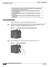
... of the Cisco IE-3000-8TC Switch 201822 Step 2 Remove the EMI protective cover from the connector on the switch. Adding Modules to the Switch Chapter 2 Switch Installation 1 Cisco IE-3000-4TC switch with Cisco IEM-3000-8TM and Cisco IEM-3000-8FM expansion modules (12 FE and 8 FX ports) 2 Cisco IE-3000-4TC switch with one Cisco IEM-3000-8FM expansion module (4 FE and 8 FX ports) 3 Cisco IE-3000-4TC...
... of the Cisco IE-3000-8TC Switch 201822 Step 2 Remove the EMI protective cover from the connector on the switch. Adding Modules to the Switch Chapter 2 Switch Installation 1 Cisco IE-3000-4TC switch with Cisco IEM-3000-8TM and Cisco IEM-3000-8FM expansion modules (12 FE and 8 FX ports) 2 Cisco IE-3000-4TC switch with one Cisco IEM-3000-8FM expansion module (4 FE and 8 FX ports) 3 Cisco IE-3000-4TC...


