Hardware Installation Guide
Page 16
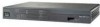
... they support. Figure 1-1 Front Panel of the Cisco 860 wireless router. Cisco 860 Series ISRs The Cisco 860 series ISRs are powered by an external power supply adapter. The various models differ in wall-mount features. Cisco 860 Series ISRs Chapter 1 Product Overview The Cisco 860 series, Cisco 880 series, and Cisco 890 series ISRs have optional rack-mount features. The...
... they support. Figure 1-1 Front Panel of the Cisco 860 wireless router. Cisco 860 Series ISRs The Cisco 860 series ISRs are powered by an external power supply adapter. The various models differ in wall-mount features. Cisco 860 Series ISRs Chapter 1 Product Overview The Cisco 860 series, Cisco 880 series, and Cisco 890 series ISRs have optional rack-mount features. The...

Hardware Installation Guide
Page 39
... The fans spin at full speed, as a diagnostic aid, immediately after the router is intended for the Cisco 880 series and 890 series ISRs and requires a 48-V external power adapter. The 3G technology is third-generation wide-area cellular technology that is an option...as security tokens and flash memory. The Cisco 860VAE series router USB port does not support eToken. The Cisco 890 series routers have a single Universal Serial Bus (USB 1.1-compliant) port located on the front panel. Cisco 860 Series, Cisco 880 Series, and Cisco 890 Series Integrated Services Routers ...
... The fans spin at full speed, as a diagnostic aid, immediately after the router is intended for the Cisco 880 series and 890 series ISRs and requires a 48-V external power adapter. The 3G technology is third-generation wide-area cellular technology that is an option...as security tokens and flash memory. The Cisco 860VAE series router USB port does not support eToken. The Cisco 890 series routers have a single Universal Serial Bus (USB 1.1-compliant) port located on the front panel. Cisco 860 Series, Cisco 880 Series, and Cisco 890 Series Integrated Services Routers ...

Hardware Installation Guide
Page 44
...media-dependent interface in crossover mode. 7. GE = Gigabit Ethernet. 5. xDSL = General term referring to an 880 or 890 series router by installing the PoE adapter card in the router and inserting the PoE 48-V external power adapter. 12. PoE = Power over plain old telephone service. 11. FXO =...3. This function can be added to various forms of supported SFPs. 1. Cisco 860 Series, Cisco 880 Series, and Cisco 890 Series Integrated Services Routers Hardware Installation Guide 1-30 OL-16193-07 IPsec = IP security. 9. DSLAM = digital subscriber line access multiplexer. 15. FE = Fast...
...media-dependent interface in crossover mode. 7. GE = Gigabit Ethernet. 5. xDSL = General term referring to an 880 or 890 series router by installing the PoE adapter card in the router and inserting the PoE 48-V external power adapter. 12. PoE = Power over plain old telephone service. 11. FXO =...3. This function can be added to various forms of supported SFPs. 1. Cisco 860 Series, Cisco 880 Series, and Cisco 890 Series Integrated Services Routers Hardware Installation Guide 1-30 OL-16193-07 IPsec = IP security. 9. DSLAM = digital subscriber line access multiplexer. 15. FE = Fast...
Hardware Installation Guide
Page 46
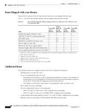
... 1 - 1 1 External 12 VDC power supply adapter 1 1 1 1 AC power supply cable with Cisco 886, 887, 887M, and 886-J models only. 5. RJ-45-to an earth ground: - Two number-10 wood screws (round- or pan-head) with the router but are required for installation: •...Cisco 880 Series, and Cisco 890 Series Integrated Services Routers Hardware Installation Guide 2-2 OL-16193-07 Shipped with Cisco 888E models only. 6. Cisco CP is optional by order and available only on some SKUs. The screws must be long enough to -dual-RJ-11 breakout cable - AWG 18 (1 mm2) or larger wire for EN...
... 1 - 1 1 External 12 VDC power supply adapter 1 1 1 1 AC power supply cable with Cisco 886, 887, 887M, and 886-J models only. 5. RJ-45-to an earth ground: - Two number-10 wood screws (round- or pan-head) with the router but are required for installation: •...Cisco 880 Series, and Cisco 890 Series Integrated Services Routers Hardware Installation Guide 2-2 OL-16193-07 Shipped with Cisco 888E models only. 6. Cisco CP is optional by order and available only on some SKUs. The screws must be long enough to -dual-RJ-11 breakout cable - AWG 18 (1 mm2) or larger wire for EN...
Hardware Installation Guide
Page 52
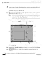
... 2-8 OL-16193-07 For the Cisco 866 and Cisco 867 models, the distance is 8.2 inches (208 mm), as shown in . 231987 1 Wall-mount holes Step 2 Step 3 Insert the screws, with anchors, into the wall. Hang the router on the screws, and place the power adapter on the underside of the Router 8.200 in. 3.673 in. 1 1 5.961...
... 2-8 OL-16193-07 For the Cisco 866 and Cisco 867 models, the distance is 8.2 inches (208 mm), as shown in . 231987 1 Wall-mount holes Step 2 Step 3 Insert the screws, with anchors, into the wall. Hang the router on the screws, and place the power adapter on the underside of the Router 8.200 in. 3.673 in. 1 1 5.961...
Hardware Installation Guide
Page 53
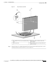
... mounted on the 3 Horizontal surface on page 2-11. Cisco 860 Series, Cisco 880 Series, and Cisco 890 Series Integrated Services Routers Hardware Installation Guide OL-16193-07 2-9 For the chassis ground connection procedures, see the "Installing the Router Ground Connection" section on which to place the wall power adapter 2 Wall-mount holes 4 Distance between the screw head...
... mounted on the 3 Horizontal surface on page 2-11. Cisco 860 Series, Cisco 880 Series, and Cisco 890 Series Integrated Services Routers Hardware Installation Guide OL-16193-07 2-9 For the chassis ground connection procedures, see the "Installing the Router Ground Connection" section on which to place the wall power adapter 2 Wall-mount holes 4 Distance between the screw head...
Hardware Installation Guide
Page 55
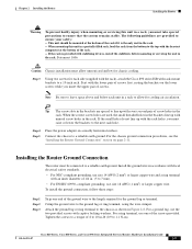
...router must raise or lower the brackets to the next rack hole. Install the ground wire in accordance with local electrical safety standards. • For NEC-compliant grounding, use size 14 AWG (2 mm2) or larger copper wire and a ring terminal with an inner diameter of 1/4 in. (5 to 7 mm). • For EN... attach the Cisco 890 series ISR with rack-mount brackets to a 19-inch rack. Step 4 Step 5 Place the power adapter on page 2-11. Attach the ground lug or ring terminal to the chassis as shown in -lb (0.9 to 1.1 N-m). Chapter 2 Installing the Router Installing the Router Warning To ...
...router must raise or lower the brackets to the next rack hole. Install the ground wire in accordance with local electrical safety standards. • For NEC-compliant grounding, use size 14 AWG (2 mm2) or larger copper wire and a ring terminal with an inner diameter of 1/4 in. (5 to 7 mm). • For EN... attach the Cisco 890 series ISR with rack-mount brackets to a 19-inch rack. Step 4 Step 5 Place the power adapter on page 2-11. Attach the ground lug or ring terminal to the chassis as shown in -lb (0.9 to 1.1 N-m). Chapter 2 Installing the Router Installing the Router Warning To ...
Hardware Installation Guide
Page 57
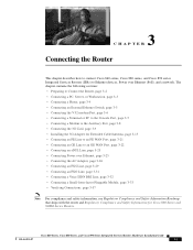
...the Auxiliary Port, page 3-8 • Connecting the 3G Card, page 3-9 • Installing the 3G Adapter for Extended Cable/Antenna, page 3-15 • Connecting an FE Line to an FE WAN Port, ...Routers. Cisco 860 Series, Cisco 880 Series, and Cisco 890 Series Integrated Services Routers Hardware Installation Guide OL-16193-07 3-1 3 C H A P T E R Connecting the Router This chapter describes how to connect Cisco 860 series, Cisco 880 series, and Cisco 890 series Integrated Services Routers (ISRs) to an GE WAN Port, page 3-22 • Connecting an xDSL Line, page 3-23 • Connecting Power...
...the Auxiliary Port, page 3-8 • Connecting the 3G Card, page 3-9 • Installing the 3G Adapter for Extended Cable/Antenna, page 3-15 • Connecting an FE Line to an FE WAN Port, ...Routers. Cisco 860 Series, Cisco 880 Series, and Cisco 890 Series Integrated Services Routers Hardware Installation Guide OL-16193-07 3-1 3 C H A P T E R Connecting the Router This chapter describes how to connect Cisco 860 series, Cisco 880 series, and Cisco 890 series Integrated Services Routers (ISRs) to an GE WAN Port, page 3-22 • Connecting an xDSL Line, page 3-23 • Connecting Power...
Hardware Installation Guide
Page 81
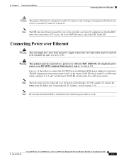
...Power over Ethernet (PoE) power adapter to your service provider and correctly configured so that the internal PoE is enabled for an RJ-45 connector only. The PoE adapter provides power to an AC outlet, see "Connecting the AC Adapter" section on the Cisco 890 series routers. Chapter 3 Connecting the Router Connecting Power... must also be provisioned by your router. Statement 353 Figure 3-24 shows how to an AC power outlet through a 12-VDC adapter. To connect the router to ports 0 and 1 of the 4-port 10/100 FE switch on the Cisco 880 series routers and ports 0,1, 2, and 3...
...Power over Ethernet (PoE) power adapter to your service provider and correctly configured so that the internal PoE is enabled for an RJ-45 connector only. The PoE adapter provides power to an AC outlet, see "Connecting the AC Adapter" section on the Cisco 890 series routers. Chapter 3 Connecting the Router Connecting Power... must also be provisioned by your router. Statement 353 Figure 3-24 shows how to an AC power outlet through a 12-VDC adapter. To connect the router to ports 0 and 1 of the 4-port 10/100 FE switch on the Cisco 880 series routers and ports 0,1, 2, and 3...
Hardware Installation Guide
Page 82
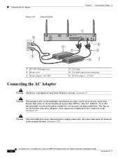
...Cisco 890 Series Integrated Services Routers Hardware Installation Guide 3-26 OL-16193-07 Ensure that a fuse or circuit breaker no larger than one power supply connection. All connections must have more than 120VAC, 20A U.S. (240VAC, 16 to 20A international) is designed to de-energize the unit. Connecting the AC Adapter... Figure 3-24 Connecting PoE Chapter 3 Connecting the Router 1 4 5 3 2 2 4 6 231995 1 48-VDC PoE input jack 2 Power cord 3 Power adapter-48 VDC Connecting the AC Adapter 4 AC plug 5 12-VDC input power-jack plug 6 Power adapter-12 VDC Warning...
...Cisco 890 Series Integrated Services Routers Hardware Installation Guide 3-26 OL-16193-07 Ensure that a fuse or circuit breaker no larger than one power supply connection. All connections must have more than 120VAC, 20A U.S. (240VAC, 16 to 20A international) is designed to de-energize the unit. Connecting the AC Adapter... Figure 3-24 Connecting PoE Chapter 3 Connecting the Router 1 4 5 3 2 2 4 6 231995 1 48-VDC PoE input jack 2 Power cord 3 Power adapter-48 VDC Connecting the AC Adapter 4 AC plug 5 12-VDC input power-jack plug 6 Power adapter-12 VDC Warning...
Hardware Installation Guide
Page 83
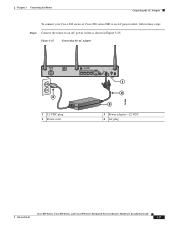
Figure 3-25 Connecting the AC Adapter 4 1 12-VDC plug 2 Power cord 1 2 3 3 Power adapter-12 VDC 4 AC plug 231996 Cisco 860 Series, Cisco 880 Series, and Cisco 890 Series Integrated Services Routers Hardware Installation Guide OL-16193-07 3-27 Chapter 3 Connecting the Router Connecting the AC Adapter To connect your Cisco 860 series or Cisco 880 series ISR to an AC power outlet, follow these steps: Step 1 Connect the router to an AC power outlet as shown in Figure 3-25.
Figure 3-25 Connecting the AC Adapter 4 1 12-VDC plug 2 Power cord 1 2 3 3 Power adapter-12 VDC 4 AC plug 231996 Cisco 860 Series, Cisco 880 Series, and Cisco 890 Series Integrated Services Routers Hardware Installation Guide OL-16193-07 3-27 Chapter 3 Connecting the Router Connecting the AC Adapter To connect your Cisco 860 series or Cisco 880 series ISR to an AC power outlet, follow these steps: Step 1 Connect the router to an AC power outlet as shown in Figure 3-25.
Hardware Installation Guide
Page 84
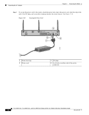
Figure 3-26 Securing the Power Cord 3 2 4 1 270659 1 Power lock clip 2 Power cord 3 DC plug 4 Lock holes on either side of the DC plug, and secure the retaining clip into the router chassis. Connecting the AC Adapter Chapter 3 Connecting the Router Step 2 To secure the power cord to the router, attach the power lock clip to the power cord, slide the clip to the end of the power connector Cisco 860 Series, Cisco 880 Series, and Cisco 890 Series Integrated Services Routers Hardware Installation Guide 3-28 OL-16193-07 See Figure 3-26.
Figure 3-26 Securing the Power Cord 3 2 4 1 270659 1 Power lock clip 2 Power cord 3 DC plug 4 Lock holes on either side of the DC plug, and secure the retaining clip into the router chassis. Connecting the AC Adapter Chapter 3 Connecting the Router Step 2 To secure the power cord to the router, attach the power lock clip to the power cord, slide the clip to the end of the power connector Cisco 860 Series, Cisco 880 Series, and Cisco 890 Series Integrated Services Routers Hardware Installation Guide 3-28 OL-16193-07 See Figure 3-26.
Hardware Installation Guide
Page 85
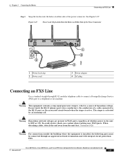
Chapter 3 Connecting the Router Connecting an FXS Line Step 3 Snap the latches into the holes on Either Side of the power connector. Figure 3-27 Power Lock Clip Latched Into the Holes on either side of the Power Connector 4 1 Power lock clip 2 Power cord 1 2 3 3 Power adapter 4 AC plug 270800 Connecting an FXS ...The ringer is OFF or ON. When detaching cables, detach the end away from the unit first. Cisco 860 Series, Cisco 880 Series, and Cisco 890 Series Integrated Services Routers Hardware Installation Guide OL-16193-07 3-29 Do not touch the RJ-11 (phone) port wires (...
Chapter 3 Connecting the Router Connecting an FXS Line Step 3 Snap the latches into the holes on Either Side of the power connector. Figure 3-27 Power Lock Clip Latched Into the Holes on either side of the Power Connector 4 1 Power lock clip 2 Power cord 1 2 3 3 Power adapter 4 AC plug 270800 Connecting an FXS ...The ringer is OFF or ON. When detaching cables, detach the end away from the unit first. Cisco 860 Series, Cisco 880 Series, and Cisco 890 Series Integrated Services Routers Hardware Installation Guide OL-16193-07 3-29 Do not touch the RJ-11 (phone) port wires (...
Hardware Installation Guide
Page 104
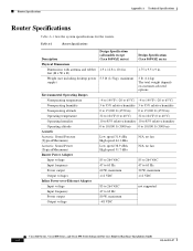
... humidity Operating altitude Acoustic Acoustic: Sound Pressure (Typical/Maximum) Acoustic: Sound Power (Typical/Maximum) Router Power Adapter Input voltage Input frequency Power output Output voltages Inline Power-over-Ethernet Adapter Input voltage Input frequency Power output Output voltage Design Specification (all models except Cisco 860VAE series) Design Specification Cisco 860VAE series 1.9 x 12.8 x 10.4 in. 1.75 x 9.5 x 9 in. 5.5 lb (2.5 kg), maximum 3 lb...
... humidity Operating altitude Acoustic Acoustic: Sound Pressure (Typical/Maximum) Acoustic: Sound Power (Typical/Maximum) Router Power Adapter Input voltage Input frequency Power output Output voltages Inline Power-over-Ethernet Adapter Input voltage Input frequency Power output Output voltage Design Specification (all models except Cisco 860VAE series) Design Specification Cisco 860VAE series 1.9 x 12.8 x 10.4 in. 1.75 x 9.5 x 9 in. 5.5 lb (2.5 kg), maximum 3 lb...


