
Hardware Installation Guide
Page 16
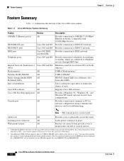
...network. Supports Cisco IOS software. You can be added at the factory or later. Wall-mount feature All Brackets on router bottom provide a way to physically secure the router. Cisco 800 Series Routers Hardware Installation ...Guide 1-2 78-5373-04 Cable lock All Provides a way to mount router on the Cisco 802 and Cisco 804 routers provide internal NT1s, the routers themselves do not function as NT1s. Compatible with 10/100-Mbps devices. Table 1-1 Cisco 800 Series Feature Summary Feature 10BASE-T Ethernet...
...network. Supports Cisco IOS software. You can be added at the factory or later. Wall-mount feature All Brackets on router bottom provide a way to physically secure the router. Cisco 800 Series Routers Hardware Installation ...Guide 1-2 78-5373-04 Cable lock All Provides a way to mount router on the Cisco 802 and Cisco 804 routers provide internal NT1s, the routers themselves do not function as NT1s. Compatible with 10/100-Mbps devices. Table 1-1 Cisco 800 Series Feature Summary Feature 10BASE-T Ethernet...

Hardware Installation Guide
Page 18
... standards. On when connected. HUB/NO HUB button (for Ethernet port) Console port Determines cable Connect PC or type for Ethernet terminal. Figure 1-4 Cisco 801 Router Back Panel Link LED Indicates state of the Cisco 800 series routers. Ethernet port Connect Ethernet network device. ISDN BRI S/T port Connect to physically secure router. Power switch l = On. = Standby or no power output...
... standards. On when connected. HUB/NO HUB button (for Ethernet port) Console port Determines cable Connect PC or type for Ethernet terminal. Figure 1-4 Cisco 801 Router Back Panel Link LED Indicates state of the Cisco 800 series routers. Ethernet port Connect Ethernet network device. ISDN BRI S/T port Connect to physically secure router. Power switch l = On. = Standby or no power output...

Hardware Installation Guide
Page 19
... 1 2 Locking power connector Connect power supply. 78-5373-04 Cisco 800 Series Routers Hardware Installation Guide 1-5 Ethernet port Connect Ethernet network device. Power switch l = On. = Standby or no power output. 11668 Cable lock Use cable lock to physically secure router. LINK HUB NO HUB ETHERNET 10 BASE T CONSOLE Cisco 802 ISDN U Cable lock Use cable lock to ISDN...
... 1 2 Locking power connector Connect power supply. 78-5373-04 Cisco 800 Series Routers Hardware Installation Guide 1-5 Ethernet port Connect Ethernet network device. Power switch l = On. = Standby or no power output. 11668 Cable lock Use cable lock to physically secure router. LINK HUB NO HUB ETHERNET 10 BASE T CONSOLE Cisco 802 ISDN U Cable lock Use cable lock to ISDN...

Hardware Installation Guide
Page 20
.... TO HUB/TO PC (for Ethernet port) Determines cable type for Ethernet device connection. IDSL port Connect to physically secure router. HUB NO HUB ETHERNET 10 BASE T 0 1 2 3 HUB/NO HUB button (for Ethernet port 0) Determines cable type for Ethernet device connection. Cisco 804 CONSOLE ISDN U Console port Connect PC or terminal. Ethernet port Connect Ethernet network device. Power switch l = On...
.... TO HUB/TO PC (for Ethernet port) Determines cable type for Ethernet device connection. IDSL port Connect to physically secure router. HUB NO HUB ETHERNET 10 BASE T 0 1 2 3 HUB/NO HUB button (for Ethernet port 0) Determines cable type for Ethernet device connection. Cisco 804 CONSOLE ISDN U Console port Connect PC or terminal. Ethernet port Connect Ethernet network device. Power switch l = On...

Hardware Installation Guide
Page 21
...secure router. Power switch l = On. = Standby or no power output. 30772 Cable lock Use cable lock to IDSL wall jack. Blinks when an Ethernet port receives a packet. Off when the Ethernet device is connected. LEDs Table 1-3 summarizes the function of each LED. On when the Ethernet.... Chapter 1 Overview LEDs Figure 1-9 Cisco 804 IDSL Router Back Panel Ethernet ports Connect Ethernet network devices. TO TO HUB PC ETHERNET 10 BASE T 1 2 3 4 TO HUB/TO PC (for Ethernet port 1) Determines cable type for Cisco 801 and 803 routers. On when the internal NT1 and the...
...secure router. Power switch l = On. = Standby or no power output. 30772 Cable lock Use cable lock to IDSL wall jack. Blinks when an Ethernet port receives a packet. Off when the Ethernet device is connected. LEDs Table 1-3 summarizes the function of each LED. On when the Ethernet.... Chapter 1 Overview LEDs Figure 1-9 Cisco 804 IDSL Router Back Panel Ethernet ports Connect Ethernet network devices. TO TO HUB PC ETHERNET 10 BASE T 1 2 3 4 TO HUB/TO PC (for Ethernet port 1) Determines cable type for Cisco 801 and 803 routers. On when the internal NT1 and the...
Hardware Installation Guide
Page 27
... Network Termination 1 (NT1) and the ISDN U cable that connects the NT1 to secure the screws. Connect the Ethernet devices to the router (for software configuration using a terminal or PC connected to the ISDN wall jack. If you have a Cisco 801 or Cisco 803 router, connect an optional digital telephone. 4. If you plan to use the cable...
... Network Termination 1 (NT1) and the ISDN U cable that connects the NT1 to secure the screws. Connect the Ethernet devices to the router (for software configuration using a terminal or PC connected to the ISDN wall jack. If you have a Cisco 801 or Cisco 803 router, connect an optional digital telephone. 4. If you plan to use the cable...

Hardware Installation Guide
Page 47
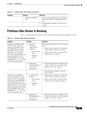
...8226; Improperly functioning network interface card (NIC) on the front panel is functioning properly. If it is, replace it is off . On the Cisco 804 IDSL router, the ETHERNET 1, 2, 3, or 4 LED on server, PC, or workstation. • Run the NIC diagnostic supplied by the vendor to ISDN or IDSL...After First Startup Problems After First Startup Table 3-2 lists problems that connects the NT1 to an Ethernet device. (On Cisco 801, Cisco 802, and 802 IDSL routers, the LINK LED on the front panel is off .) • If you are securely seated. • Make sure the cable is off .
...8226; Improperly functioning network interface card (NIC) on the front panel is functioning properly. If it is, replace it is off . On the Cisco 804 IDSL router, the ETHERNET 1, 2, 3, or 4 LED on server, PC, or workstation. • Run the NIC diagnostic supplied by the vendor to ISDN or IDSL...After First Startup Problems After First Startup Table 3-2 lists problems that connects the NT1 to an Ethernet device. (On Cisco 801, Cisco 802, and 802 IDSL routers, the LINK LED on the front panel is off .) • If you are securely seated. • Make sure the cable is off .
Hardware Installation Guide
Page 49
...is not physically damaged. Damaged cable. On the Cisco 804 IDSL router, the ETHERNET 1, 2, 3, or 4 LED on the front panel blinks.) • One of the following order: • Make sure the connectors at both ends of the cable are securely connected. • Make sure the cable is off... . Disconnected cable. - Disconnected cable. - If it is off. On the Cisco 804 IDSL router, the ETHERNET 1, 2, 3, or 4 LED on the front panel is not physically...
...is not physically damaged. Damaged cable. On the Cisco 804 IDSL router, the ETHERNET 1, 2, 3, or 4 LED on the front panel blinks.) • One of the following order: • Make sure the connectors at both ends of the cable are securely connected. • Make sure the cable is off... . Disconnected cable. - Disconnected cable. - If it is off. On the Cisco 804 IDSL router, the ETHERNET 1, 2, 3, or 4 LED on the front panel is not physically...

