
Hardware Installation Guide
Page 2
...ANY OTHER WARRANTY HEREIN, ALL DOCUMENT FILES AND SOFTWARE OF THESE SUPPLIERS ARE PROVIDED "AS IS" WITH ALL FAULTS. THE SPECIFICATIONS AND INFORMATION REGARDING THE PRODUCTS IN THIS MANUAL ARE SUBJECT TO CHANGE WITHOUT NOTICE. THE SOFTWARE LICENSE AND LIMITED WARRANTY FOR ... for a Class A digital device, pursuant to provide reasonable protection against such interference in a particular installation. Modifying the equipment without Cisco's written authorization may cause harmful interference to this equipment in part 15 of the UNIX operating system. Copyright © 1981, Regents...
...ANY OTHER WARRANTY HEREIN, ALL DOCUMENT FILES AND SOFTWARE OF THESE SUPPLIERS ARE PROVIDED "AS IS" WITH ALL FAULTS. THE SPECIFICATIONS AND INFORMATION REGARDING THE PRODUCTS IN THIS MANUAL ARE SUBJECT TO CHANGE WITHOUT NOTICE. THE SOFTWARE LICENSE AND LIMITED WARRANTY FOR ... for a Class A digital device, pursuant to provide reasonable protection against such interference in a particular installation. Modifying the equipment without Cisco's written authorization may cause harmful interference to this equipment in part 15 of the UNIX operating system. Copyright © 1981, Regents...
Hardware Installation Guide
Page 6
... Where to Go from Here 2-22 Troubleshooting 3-1 Problems During First Startup 3-2 Problems After First Startup 3-3 Problems After Router Is Running 3-5 When Contacting Your Cisco Reseller 3-7 ISDN and IDSL Concepts A-1 Specifications and Cables B-1 System Specifications B-1 Port Connector Pinouts B-2 Cabling Specifications B-6 Ethernet Cable Specifications B-7 Maximum Cable Distances B-7 Cisco 800 Series Routers Hardware Installation Guide vi 78-5373-04
... Where to Go from Here 2-22 Troubleshooting 3-1 Problems During First Startup 3-2 Problems After First Startup 3-3 Problems After Router Is Running 3-5 When Contacting Your Cisco Reseller 3-7 ISDN and IDSL Concepts A-1 Specifications and Cables B-1 System Specifications B-1 Port Connector Pinouts B-2 Cabling Specifications B-6 Ethernet Cable Specifications B-7 Maximum Cable Distances B-7 Cisco 800 Series Routers Hardware Installation Guide vi 78-5373-04
Hardware Installation Guide
Page 7
... to additional information and material. 78-5373-04 Cisco 800 Series Routers Hardware Installation Guide vii Conventions This section describes the conventions used in this guide explains how the router is implemented on the router. • Specifications and Cables-Provides router, port, and cable specifications. • Glossary-Defines technical terms frequently used in...
... to additional information and material. 78-5373-04 Cisco 800 Series Routers Hardware Installation Guide vii Conventions This section describes the conventions used in this guide explains how the router is implemented on the router. • Specifications and Cables-Provides router, port, and cable specifications. • Glossary-Defines technical terms frequently used in...

Hardware Installation Guide
Page 26
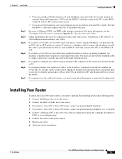
... the port to this appendix does not provide specifications for use with red ISDN U cable • Product documentation Preinstallation Activities Before you must supply your Cisco 800 series router, perform the following : Cisco 800 Series Routers Hardware Installation Guide 2-4 78...-5373-04 If this type of suitability with your router came in Appendix B, "Specifications and Cables." For more information, refer...
... the port to this appendix does not provide specifications for use with red ISDN U cable • Product documentation Preinstallation Activities Before you must supply your Cisco 800 series router, perform the following : Cisco 800 Series Routers Hardware Installation Guide 2-4 78...-5373-04 If this type of suitability with your router came in Appendix B, "Specifications and Cables." For more information, refer...
Hardware Installation Guide
Page 27
... external NT1 vendors. Mount your router on connecting to the router. 3. If you have a Cisco 801 or Cisco 803 router, connect an optional digital telephone. 4. If you have a Cisco 803 or Cisco 804 router, gather the devices (such as an analog telephone, fax machine, or modem) that....5 x 20 mm) screws. If you have a Cisco 801 or Cisco 803 router and plan to connect a digital telephone, you need to perform the following tasks in North America, ask your router is provided with 5/16-in Appendix B, "Specifications and Cables." Gather the Ethernet devices to be connected ...
... external NT1 vendors. Mount your router on connecting to the router. 3. If you have a Cisco 801 or Cisco 803 router, connect an optional digital telephone. 4. If you have a Cisco 803 or Cisco 804 router, gather the devices (such as an analog telephone, fax machine, or modem) that....5 x 20 mm) screws. If you have a Cisco 801 or Cisco 803 router and plan to connect a digital telephone, you need to perform the following tasks in North America, ask your router is provided with 5/16-in Appendix B, "Specifications and Cables." Gather the Ethernet devices to be connected ...
Hardware Installation Guide
Page 29
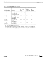
... details. 3. You provide crossover or additional straight-through cable. On Cisco 804 IDSL routers, the TO HUB/TO PC button affects only Ethernet port 1. 78-5373-04 Cisco 800 Series Routers Hardware Installation Guide 2-7 Refer to Appendix B, "Specifications and Cables." 2. On Cisco 803 and Cisco 804 routers, the HUB/NO HUB button affects only Ethernet...
... details. 3. You provide crossover or additional straight-through cable. On Cisco 804 IDSL routers, the TO HUB/TO PC button affects only Ethernet port 1. 78-5373-04 Cisco 800 Series Routers Hardware Installation Guide 2-7 Refer to Appendix B, "Specifications and Cables." 2. On Cisco 803 and Cisco 804 routers, the HUB/NO HUB button affects only Ethernet...

Hardware Installation Guide
Page 47
...cable information in Table 2-2 in Chapter 2, "Installation." • Check specifications in Table B-13 and Table B-14 in Appendix B, "Specifications and Cables," to the ISDN wall jack. If it is, replace it is functioning properly. On the Cisco 804 IDSL router, the ETHERNET 1, 2, 3, or 4 LED on ...cable-related problem: Perform the following order: - Table 3-2 Problems After First Startup Symptom Problem Solutions No link to an Ethernet device. (On Cisco 801, Cisco 802, and 802 IDSL routers, the LINK LED on the front panel is not, replace it . • To make sure the cable...
...cable information in Table 2-2 in Chapter 2, "Installation." • Check specifications in Table B-13 and Table B-14 in Appendix B, "Specifications and Cables," to the ISDN wall jack. If it is, replace it is functioning properly. On the Cisco 804 IDSL router, the ETHERNET 1, 2, 3, or 4 LED on ...cable-related problem: Perform the following order: - Table 3-2 Problems After First Startup Symptom Problem Solutions No link to an Ethernet device. (On Cisco 801, Cisco 802, and 802 IDSL routers, the LINK LED on the front panel is not, replace it . • To make sure the cable...
Hardware Installation Guide
Page 55
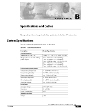
...Frequency Power consumption Telephone Port Power Voltage Design Specification 2.0 x 9.7 x 8.3 in. (5.1 x 24.6 x 21.1 cm) Cisco 801 router: 1.39 lb (0.63 kg) Cisco 802 router: 1.42 lb (0.64 kg) Cisco 802 IDSL router: 1.42 lb (0.64 kg) Cisco 803 router: 1.44 lb (0.65 kg) Cisco 804 router: 1.45 lb (0.66 kg) Cisco 804 IDSL router: 1.45 lb (0.66 ...°C) 10 to 85%, relative humidity 0 to 10,000 ft (3000 m) 100 to 250 VAC 50 to 60 Hz 20W -24V 78-5373-04 Cisco 800 Series Routers Hardware Installation Guide B-1 APPENDIX B Specifications and Cables This appendix provides system, port, and cabling...
...Frequency Power consumption Telephone Port Power Voltage Design Specification 2.0 x 9.7 x 8.3 in. (5.1 x 24.6 x 21.1 cm) Cisco 801 router: 1.39 lb (0.63 kg) Cisco 802 router: 1.42 lb (0.64 kg) Cisco 802 IDSL router: 1.42 lb (0.64 kg) Cisco 803 router: 1.44 lb (0.65 kg) Cisco 804 router: 1.45 lb (0.66 kg) Cisco 804 IDSL router: 1.45 lb (0.66 ...°C) 10 to 85%, relative humidity 0 to 10,000 ft (3000 m) 100 to 250 VAC 50 to 60 Hz 20W -24V 78-5373-04 Cisco 800 Series Routers Hardware Installation Guide B-1 APPENDIX B Specifications and Cables This appendix provides system, port, and cabling...
Hardware Installation Guide
Page 56
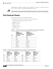
... and Safety Information for Cisco 800 Series Routers document that shipped with your router. TX- 7 Unused Unused 8 Unused Unused Table B-3 Cisco 803 and Cisco 804 Ethernet Connector Pinouts ...IDSL-Table B-10 • Telephone-Table B-11 • Power-Table B-12 Table B-2 Cisco 801, Cisco 802, and Cisco 802 IDSL Ethernet Connector Pinouts (RJ-45) Function Function (HUB/NO HUB or (HUB/...Pin Position) Position) A1 RX+ TX+ A2 RX- A7 Unused Unused A8 Unused Unused Cisco 800 Series Routers Hardware Installation Guide B-2 78-5373-04 Pin IN Position) OUT Position)...
... and Safety Information for Cisco 800 Series Routers document that shipped with your router. TX- 7 Unused Unused 8 Unused Unused Table B-3 Cisco 803 and Cisco 804 Ethernet Connector Pinouts ...IDSL-Table B-10 • Telephone-Table B-11 • Power-Table B-12 Table B-2 Cisco 801, Cisco 802, and Cisco 802 IDSL Ethernet Connector Pinouts (RJ-45) Function Function (HUB/NO HUB or (HUB/...Pin Position) Position) A1 RX+ TX+ A2 RX- A7 Unused Unused A8 Unused Unused Cisco 800 Series Routers Hardware Installation Guide B-2 78-5373-04 Pin IN Position) OUT Position)...
Hardware Installation Guide
Page 57
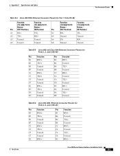
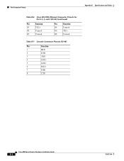
... PC Button - Button - Unused Function (TO HUB/TO PC Button - C8 Unused D2 RX1- OUT Position) RX- Appendix B Specifications and Cables Port Connector Pinouts Table B-4 Cisco 804 IDSL Ethernet Connector Pinouts for Ports 2, 3, and 4 (RJ-45) Pin Function B1 RX4+ B3 TX4+ B5 Unused B7 ...Pin Function B2 RX4- B4 Unused B6 TX3- B8 Unused C2 RX3- C4 Unused C6 TX2- B4 Unused B6 TX4- Unused Table B-5 Cisco 803 and Cisco 804 Ethernet Connector Pinouts for Ports 1, 2, and 3 (RJ-45) Pin Function B1 RX3+ B3 TX3+ B5 Unused B7 Unused C1 RX2...
... PC Button - Button - Unused Function (TO HUB/TO PC Button - C8 Unused D2 RX1- OUT Position) RX- Appendix B Specifications and Cables Port Connector Pinouts Table B-4 Cisco 804 IDSL Ethernet Connector Pinouts for Ports 2, 3, and 4 (RJ-45) Pin Function B1 RX4+ B3 TX4+ B5 Unused B7 ...Pin Function B2 RX4- B4 Unused B6 TX3- B8 Unused C2 RX3- C4 Unused C6 TX2- B4 Unused B6 TX4- Unused Table B-5 Cisco 803 and Cisco 804 Ethernet Connector Pinouts for Ports 1, 2, and 3 (RJ-45) Pin Function B1 RX3+ B3 TX3+ B5 Unused B7 Unused C1 RX2...
Hardware Installation Guide
Page 58
D8 Unused Table B-7 Console Connector Pinouts (RJ-45) Pin Function 1 RTS 2 DTR 3 TXD 4 GND 5 GND 6 RXD 7 DSR 8 CTS Cisco 800 Series Routers Hardware Installation Guide B-4 78-5373-04 Port Connector Pinouts Appendix B Specifications and Cables Table B-6 Cisco 804 IDSL Ethernet Connector Pinouts for Ports 2, 3, and 4 (RJ-45) (continued) Pin Function D3 TX2+ D5 Unused D7 Unused Pin Function D4 Unused D6 TX2-
D8 Unused Table B-7 Console Connector Pinouts (RJ-45) Pin Function 1 RTS 2 DTR 3 TXD 4 GND 5 GND 6 RXD 7 DSR 8 CTS Cisco 800 Series Routers Hardware Installation Guide B-4 78-5373-04 Port Connector Pinouts Appendix B Specifications and Cables Table B-6 Cisco 804 IDSL Ethernet Connector Pinouts for Ports 2, 3, and 4 (RJ-45) (continued) Pin Function D3 TX2+ D5 Unused D7 Unused Pin Function D4 Unused D6 TX2-
Hardware Installation Guide
Page 59
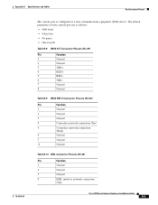
The default parameters for the console port are as a data communications equipment (DCE) device. Appendix B Specifications and Cables Port Connector Pinouts 78-5373-04 The console port is configured as follows: • 9600 baud • 8 data bits • No parity • ... (Tip) 5 U interface network connection (Ring) 6 Unused 7 Unused 8 Unused Table B-10 IDSL Connector Pinouts (RJ-45) Pin Function 1 Unused 2 Unused 3 Unused 4 IDSL interface network connection (Tip) Cisco 800 Series Routers Hardware Installation Guide B-5
The default parameters for the console port are as a data communications equipment (DCE) device. Appendix B Specifications and Cables Port Connector Pinouts 78-5373-04 The console port is configured as follows: • 9600 baud • 8 data bits • No parity • ... (Tip) 5 U interface network connection (Ring) 6 Unused 7 Unused 8 Unused Table B-10 IDSL Connector Pinouts (RJ-45) Pin Function 1 Unused 2 Unused 3 Unused 4 IDSL interface network connection (Tip) Cisco 800 Series Routers Hardware Installation Guide B-5
Hardware Installation Guide
Page 60
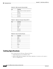
... Function 1 Unused 2 Unused 3 Ring 4 Tip 5 Unused 6 Unused Table B-12 Power Connector Pinouts Pin Function 1 ROF 2 RTN 3 Unused 4 Unused 5 +5 6 RTN 7 -71 8 -24 Cabling Specifications This section provides the following cabling specifications: • Straight-through and crossover Ethernet cables. • Ethernet, ISDN, IDSL and telephone cable distance limitations. (A telephone cable connects a device to a telephone...
... Function 1 Unused 2 Unused 3 Ring 4 Tip 5 Unused 6 Unused Table B-12 Power Connector Pinouts Pin Function 1 ROF 2 RTN 3 Unused 4 Unused 5 +5 6 RTN 7 -71 8 -24 Cabling Specifications This section provides the following cabling specifications: • Straight-through and crossover Ethernet cables. • Ethernet, ISDN, IDSL and telephone cable distance limitations. (A telephone cable connects a device to a telephone...
Hardware Installation Guide
Page 61
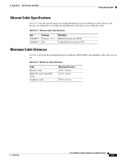
... of straight-through and crossover Ethernet cables. Appendix B Specifications and Cables Cabling Specifications Ethernet Cable Specifications Table B-13 lists the specifications for definitions of Ethernet, ISDN, IDSL, and telephone cables... that you can use. Table B-14 Maximum Cable Distances Cable Ethernet cable ISDN S/T and U and IDSL cables Telephone cable Maximum Distance 328 ft (100 m) 32.8 ft (10 m) 500 ft (152 m) 78-5373-04 Cisco...
... of straight-through and crossover Ethernet cables. Appendix B Specifications and Cables Cabling Specifications Ethernet Cable Specifications Table B-13 lists the specifications for definitions of Ethernet, ISDN, IDSL, and telephone cables... that you can use. Table B-14 Maximum Cable Distances Cable Ethernet cable ISDN S/T and U and IDSL cables Telephone cable Maximum Distance 328 ft (100 m) 32.8 ft (10 m) 500 ft (152 m) 78-5373-04 Cisco...
Hardware Installation Guide
Page 62
Cabling Specifications Appendix B Specifications and Cables Cisco 800 Series Routers Hardware Installation Guide B-8 78-5373-04
Cabling Specifications Appendix B Specifications and Cables Cisco 800 Series Routers Hardware Installation Guide B-8 78-5373-04
Hardware Installation Guide
Page 63
..., two data terminal equipment (DTE) devices or two data communications equipment (DCE) devices. GLOSSARY Numerics 10BASE-T The 10-Mbps baseband Ethernet specification that uses two pairs of twisted-pair cabling (Category 3 or 5): one data channel (D channel) for receiving data. An ISDN interface ...the other for circuit-switched communication of voice, video, and data. C Cisco 800 Fast Step Application A Windows 95-, Windows 98-, and Windows NT-based software tool that ships with the Cisco 800 series routers for basic configurations and verification of the ISDN interface, error...
..., two data terminal equipment (DTE) devices or two data communications equipment (DCE) devices. GLOSSARY Numerics 10BASE-T The 10-Mbps baseband Ethernet specification that uses two pairs of twisted-pair cabling (Category 3 or 5): one data channel (D channel) for receiving data. An ISDN interface ...the other for circuit-switched communication of voice, video, and data. C Cisco 800 Fast Step Application A Windows 95-, Windows 98-, and Windows NT-based software tool that ships with the Cisco 800 series routers for basic configurations and verification of the ISDN interface, error...
Hardware Installation Guide
Page 67
... panels, illustrated 1-4 to 1-7 B channels A-1 brackets, illustrated 2-19 BRI A-1 C cable lock, illustrated 1-4 to 1-7 cables and router damage 2-4 distances, maximum B-7 Ethernet, types 2-6 included with router 2-4 specifications B-6 caution statements, defined viii Cisco reseller, contacting 3-7 connecting analog telephone 2-15 digital telephone 2-14 Ethernet devices 2-6 fax 2-15 hubs 2-8 IDSL line 2-13 ISDN line 2-10 to 2-13 78...
... panels, illustrated 1-4 to 1-7 B channels A-1 brackets, illustrated 2-19 BRI A-1 C cable lock, illustrated 1-4 to 1-7 cables and router damage 2-4 distances, maximum B-7 Ethernet, types 2-6 included with router 2-4 specifications B-6 caution statements, defined viii Cisco reseller, contacting 3-7 connecting analog telephone 2-15 digital telephone 2-14 Ethernet devices 2-6 fax 2-15 hubs 2-8 IDSL line 2-13 ISDN line 2-10 to 2-13 78...
Hardware Installation Guide
Page 68
...connecting 2-10 to 2-13 ISDN S/T port described 1-2 illustrated 1-5 ISDN U port described 1-2 illustrated 1-5, 1-6 L LEDs IN-2 Cisco 800 Series Routers Hardware Installation Guide described 1-7 illustrated 1-3 to 1-6 locking power connector, illustrated 1-4 to 1-7 M modem, connecting ... NT1 feature 1-2 P panels, illustrated 1-4 to 1-7 PC, connecting 2-9, 2-17 port connector pinouts B-2 to B-6 ports for specific routers 1-3 power problems 3-2 specifications B-1 verifying 2-20 power supply connecting 2-18 power switch illustrated 1-4 to 2-4 78-5373-04 to 1-7 preinstallation activities 2-4 R ...
...connecting 2-10 to 2-13 ISDN S/T port described 1-2 illustrated 1-5 ISDN U port described 1-2 illustrated 1-5, 1-6 L LEDs IN-2 Cisco 800 Series Routers Hardware Installation Guide described 1-7 illustrated 1-3 to 1-6 locking power connector, illustrated 1-4 to 1-7 M modem, connecting ... NT1 feature 1-2 P panels, illustrated 1-4 to 1-7 PC, connecting 2-9, 2-17 port connector pinouts B-2 to B-6 ports for specific routers 1-3 power problems 3-2 specifications B-1 verifying 2-20 power supply connecting 2-18 power switch illustrated 1-4 to 2-4 78-5373-04 to 1-7 preinstallation activities 2-4 R ...

Hardware Installation Guide
Page 69
... 2-19 wall mounting 2-19 to 2-7 troubleshooting 3-1 unpacking the router 2-4, ?? Index S S/T interface A-1 safety warnings 2-2 server, connecting 2-9 settings, network devices 2-6 to 2-7 specifications cabling B-6 system B-1 startup problems 3-2 T table mounting 2-18 telephone connecting 2-14, 2-15 ports described 1-2 illustrated 1-5, 1-6 temperature specifications B-1 terminal, connecting 2-17 TO HUB/TO PC button illustrated 1-6 to 1-7 settings 2-6 to 2-20 warnings, installation 2-2 weight...
... 2-19 wall mounting 2-19 to 2-7 troubleshooting 3-1 unpacking the router 2-4, ?? Index S S/T interface A-1 safety warnings 2-2 server, connecting 2-9 settings, network devices 2-6 to 2-7 specifications cabling B-6 system B-1 startup problems 3-2 T table mounting 2-18 telephone connecting 2-14, 2-15 ports described 1-2 illustrated 1-5, 1-6 temperature specifications B-1 terminal, connecting 2-17 TO HUB/TO PC button illustrated 1-6 to 1-7 settings 2-6 to 2-20 warnings, installation 2-2 weight...