Hardware Installation Guide
Page 2
... OTHER WARRANTY HEREIN, ALL DOCUMENT FILES AND SOFTWARE OF THESE SUPPLIERS ARE PROVIDED "AS IS" WITH ALL FAULTS. However, there is an adaptation of the FCC rules. These limits are designed to comply with the instruction manual, may cause interference with FCC requirements for a Class B digital device in accordance with the specifications in a residential installation. This equipment has been...
... OTHER WARRANTY HEREIN, ALL DOCUMENT FILES AND SOFTWARE OF THESE SUPPLIERS ARE PROVIDED "AS IS" WITH ALL FAULTS. However, there is an adaptation of the FCC rules. These limits are designed to comply with the instruction manual, may cause interference with FCC requirements for a Class B digital device in accordance with the specifications in a residential installation. This equipment has been...
Hardware Installation Guide
Page 7
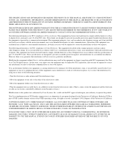
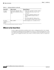
... guide. Notes contain helpful suggestions or references to the network as quickly as possible. Where relevant, this guide. The goal of all levels of router LEDs, ports, and other components. • Installation-Provides information on the router. • Specifications and Cables-Provides router, port, and cable specifications. • Glossary-Defines technical terms frequently used in installing routers. Conventions This section describes the conventions used in this guide, and how to access related documentation...
... guide. Notes contain helpful suggestions or references to the network as quickly as possible. Where relevant, this guide. The goal of all levels of router LEDs, ports, and other components. • Installation-Provides information on the router. • Specifications and Cables-Provides router, port, and cable specifications. • Glossary-Defines technical terms frequently used in installing routers. Conventions This section describes the conventions used in this guide, and how to access related documentation...
Hardware Installation Guide
Page 10
...: • Emergencies - Documentation Feedback You can submit comments by using the response card (if present) behind the front cover of security advisories and notices for Cisco products is available at this URL: http://www.cisco.com/en/US/products/products_psirt_rss_feed.html Reporting Security Problems in real time, you prefer to see advisories and notices as they are updated in Cisco Products Cisco is committed...
...: • Emergencies - Documentation Feedback You can submit comments by using the response card (if present) behind the front cover of security advisories and notices for Cisco products is available at this URL: http://www.cisco.com/en/US/products/products_psirt_rss_feed.html Reporting Security Problems in real time, you prefer to see advisories and notices as they are updated in Cisco Products Cisco is committed...
Hardware Installation Guide
Page 11
... serial number before placing a service call. 78-5373-04 Cisco 800 Series Routers Hardware Installation Guide xi Never use a revoked or an expired encryption key. In addition, Cisco Technical Assistance Center (TAC) engineers provide telephone support. Locate the serial number label on Cisco.com features extensive online support resources. The Cisco Technical Support Website on your product and record the information before submitting a web or phone request for troubleshooting and...
... serial number before placing a service call. 78-5373-04 Cisco 800 Series Routers Hardware Installation Guide xi Never use a revoked or an expired encryption key. In addition, Cisco Technical Assistance Center (TAC) engineers provide telephone support. Locate the serial number label on Cisco.com features extensive online support resources. The Cisco Technical Support Website on your product and record the information before submitting a web or phone request for troubleshooting and...
Hardware Installation Guide
Page 16
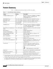
...-T Ethernet port(s) ISDN BRI S/T port ISDN BRI U port IDSL port Telephone ports Internal Network Termination 1 (NT1) Flash memory Dynamic RAM (DRAM) Easily distinguishable ISDN B-channel LEDs Ease of error. Locking power connector All Locks power connector in place. The Cisco product number for the 8-MB Flash memory upgrade kit is a service port. Supports Cisco IOS software. Provides connection to IDSL network. Provides connection to Cisco 802 and Cisco 804 routers. 2. Color-coded ports and cables to reduce the chance of installation Cisco IOS software Cisco 800...
...-T Ethernet port(s) ISDN BRI S/T port ISDN BRI U port IDSL port Telephone ports Internal Network Termination 1 (NT1) Flash memory Dynamic RAM (DRAM) Easily distinguishable ISDN B-channel LEDs Ease of error. Locking power connector All Locks power connector in place. The Cisco product number for the 8-MB Flash memory upgrade kit is a service port. Supports Cisco IOS software. Provides connection to IDSL network. Provides connection to Cisco 802 and Cisco 804 routers. 2. Color-coded ports and cables to reduce the chance of installation Cisco IOS software Cisco 800...

Hardware Installation Guide
Page 18
... not connect the port to a public network that follows the European Union standards. Power switch l = On. = Standby or no power output. 11666 LINK HUB NO HUB ETHERNET 10 BASE T Cisco 801 CONSOLE ISDN S/T Cable lock Use cable lock to external NT1 or ISDN wall jack. Locking power connector Connect power supply. ISDN BRI S/T port Connect to physically secure router. device connection. Figure 1-4 Cisco 801 Router Back Panel Link LED Indicates state of the Cisco 800 series routers. Cisco 800 Series Routers Hardware Installation Guide...
... not connect the port to a public network that follows the European Union standards. Power switch l = On. = Standby or no power output. 11666 LINK HUB NO HUB ETHERNET 10 BASE T Cisco 801 CONSOLE ISDN S/T Cable lock Use cable lock to external NT1 or ISDN wall jack. Locking power connector Connect power supply. ISDN BRI S/T port Connect to physically secure router. device connection. Figure 1-4 Cisco 801 Router Back Panel Link LED Indicates state of the Cisco 800 series routers. Cisco 800 Series Routers Hardware Installation Guide...

Hardware Installation Guide
Page 19
...HUB button (for Ethernet port 0) Determines cable type for Ethernet device connection. Console port Connect PC or terminal. PHONE 1 2 Locking power connector Connect power supply. 78-5373-04 Cisco 800 Series Routers Hardware Installation Guide 1-5 Console port Connect PC or terminal. ISDN BRI S/T port Connect to telephone, fax machine, or modem. HUB/NO HUB button (for Ethernet port) Determines cable type for Ethernet device connection. Telephone ports Connect to external NT1 or ISDN wall jack. Power switch l = On. = Standby or no power output. 11668 Cable lock Use cable...
...HUB button (for Ethernet port 0) Determines cable type for Ethernet device connection. Console port Connect PC or terminal. PHONE 1 2 Locking power connector Connect power supply. 78-5373-04 Cisco 800 Series Routers Hardware Installation Guide 1-5 Console port Connect PC or terminal. ISDN BRI S/T port Connect to telephone, fax machine, or modem. HUB/NO HUB button (for Ethernet port) Determines cable type for Ethernet device connection. Telephone ports Connect to external NT1 or ISDN wall jack. Power switch l = On. = Standby or no power output. 11668 Cable lock Use cable...

Hardware Installation Guide
Page 20
...Link LED Indicates state of Ethernet port. LINK TO TO HUB PC ETHERNET 10 BASE T CONSOLE Cisco 802 IDSL IDSL Cable lock Use cable lock to telephone, fax machine, or modem. Locking power connector Connect power supply. 30771 Cisco 800 Series Routers Hardware Installation Guide 1-6 78-5373-04 Telephone ports Connect to physically secure router. Power switch l = On. = Standby or no power output. 11669 Cable lock Use cable lock to physically secure router. TO HUB/TO PC (for Ethernet port) Determines cable type for Ethernet device connection. Console port Connect...
...Link LED Indicates state of Ethernet port. LINK TO TO HUB PC ETHERNET 10 BASE T CONSOLE Cisco 802 IDSL IDSL Cable lock Use cable lock to telephone, fax machine, or modem. Locking power connector Connect power supply. 30771 Cisco 800 Series Routers Hardware Installation Guide 1-6 78-5373-04 Telephone ports Connect to physically secure router. Power switch l = On. = Standby or no power output. 11669 Cable lock Use cable lock to physically secure router. TO HUB/TO PC (for Ethernet port) Determines cable type for Ethernet device connection. Console port Connect...

Hardware Installation Guide
Page 21
... a problem. Locking power connector Connect power supply. On when the Ethernet device is connected. TO TO HUB PC ETHERNET 10 BASE T 1 2 3 4 TO HUB/TO PC (for Ethernet port 1) Determines cable type for Cisco 801 and 803 routers. On when the ISDN interface and the ISDN terminal device are synchronized. Blinks when an Ethernet port receives a packet. On when the Ethernet device is connected. Cisco 804 IDSL routers only. Power switch l = On. = Standby or no power output. 30772 Cable lock Use cable...
... a problem. Locking power connector Connect power supply. On when the Ethernet device is connected. TO TO HUB PC ETHERNET 10 BASE T 1 2 3 4 TO HUB/TO PC (for Ethernet port 1) Determines cable type for Cisco 801 and 803 routers. On when the ISDN interface and the ISDN terminal device are synchronized. Blinks when an Ethernet port receives a packet. On when the Ethernet device is connected. Cisco 804 IDSL routers only. Power switch l = On. = Standby or no power output. 30772 Cable lock Use cable...
Hardware Installation Guide
Page 22
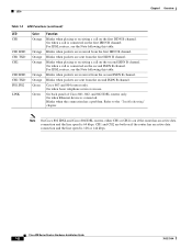
... a call is connected on the first ISDN B channel. Cisco 803 and 804 routers only. Refer to the "Troubleshooting" chapter. Cisco 800 Series Routers Hardware Installation Guide 1-8 78-5373-04 On when Ethernet device is in use. Blinks when the connection has a problem. Note On Cisco 802 IDSL and Cisco 804 IDSL routers, either CH1 or CH2 is on if the router has an active data connection and the line speed is 128...
... a call is connected on the first ISDN B channel. Cisco 803 and 804 routers only. Refer to the "Troubleshooting" chapter. Cisco 800 Series Routers Hardware Installation Guide 1-8 78-5373-04 On when Ethernet device is in use. Blinks when the connection has a problem. Note On Cisco 802 IDSL and Cisco 804 IDSL routers, either CH1 or CH2 is on if the router has an active data connection and the line speed is 128...
Hardware Installation Guide
Page 24
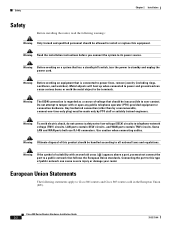
... (EU). Warning The ISDN connection is connected to user contact. Connecting the port to this equipment. Use caution when connecting cables. Cisco 800 Series Routers Hardware Installation Guide 2-2 78-5373-04 Some LAN and WAN ports both use RJ-45 connectors. Warning Before working on a system that is regarded as a source of public network can cause serious burns or weld the metal object to its power source. Do not attempt...
... (EU). Warning The ISDN connection is connected to user contact. Connecting the port to this equipment. Use caution when connecting cables. Cisco 800 Series Routers Hardware Installation Guide 2-2 78-5373-04 Some LAN and WAN ports both use RJ-45 connectors. Warning Before working on a system that is regarded as a source of public network can cause serious burns or weld the metal object to its power source. Do not attempt...

Hardware Installation Guide
Page 26
... routers) • Ethernet cable (yellow) • ISDN U or IDSL cable (red) (Cisco 802, 802 IDSL, 804, and 804 IDSL routers) • RJ-45-to-RJ-11 adapter cable for a particular cable, we strongly recommend ordering the cable from your router. For more information, refer to the Cisco 800 Series Routers Software Configuration Guide. Preventing Router Damage Chapter 2 Installation Preventing Router Damage Use the following guidelines when connecting devices to your router: • Connect the color-coded cables supplied...
... routers) • Ethernet cable (yellow) • ISDN U or IDSL cable (red) (Cisco 802, 802 IDSL, 804, and 804 IDSL routers) • RJ-45-to-RJ-11 adapter cable for a particular cable, we strongly recommend ordering the cable from your router. For more information, refer to the Cisco 800 Series Routers Software Configuration Guide. Preventing Router Damage Chapter 2 Installation Preventing Router Damage Use the following guidelines when connecting devices to your router: • Connect the color-coded cables supplied...
Hardware Installation Guide
Page 27
... B, "Specifications and Cables." If the wall on connecting to the ISDN wall jack. Connect the router to connect each device (usually this cable is provided with the device). Verify the router installation. 78-5373-04 Cisco 800 Series Routers Hardware Installation Guide 2-5 If you instead need to the router, provide the terminal or PC. Installing Your Router To install the Cisco 800 series routers, you must also provide the telephone cable to the power source...
... B, "Specifications and Cables." If the wall on connecting to the ISDN wall jack. Connect the router to connect each device (usually this cable is provided with the device). Verify the router installation. 78-5373-04 Cisco 800 Series Routers Hardware Installation Guide 2-5 If you instead need to the router, provide the terminal or PC. Installing Your Router To install the Cisco 800 series routers, you must also provide the telephone cable to the power source...
Hardware Installation Guide
Page 44
..., fax, or modem • CH1 TXD, CH2 TXD: Blinking when indicated ISDN B channel sends a packet. Cisco strongly recommends that inexperienced network administrators use the CLI to configure the software, refer to the Cisco 800 Series Routers Software Configuration Guide. 2-22 Cisco 800 Series Routers Hardware Installation Guide 78-5373-04 CH1 or CH2 is in use. 1. Use the Cisco 800 Fast Step CD-ROM and online help. Where to configure the software. Where to...
..., fax, or modem • CH1 TXD, CH2 TXD: Blinking when indicated ISDN B channel sends a packet. Cisco strongly recommends that inexperienced network administrators use the CLI to configure the software, refer to the Cisco 800 Series Routers Software Configuration Guide. 2-22 Cisco 800 Series Routers Hardware Installation Guide 78-5373-04 CH1 or CH2 is in use. 1. Use the Cisco 800 Fast Step CD-ROM and online help. Where to configure the software. Where to...

Hardware Installation Guide
Page 47
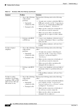
... HUB button • To make sure you have cabled the devices correctly, see Table 2-2 in Chapter 2, "Installation." • Improperly functioning network interface card (NIC) on the front panel is off .) • A cable-related problem: Perform the following tasks in parts of Europe, you might need to connect the router to an external NT1 and connect the NT1 to an Ethernet device. (On Cisco 801, Cisco 802, and 802 IDSL routers, the LINK LED...
... HUB button • To make sure you have cabled the devices correctly, see Table 2-2 in Chapter 2, "Installation." • Improperly functioning network interface card (NIC) on the front panel is off .) • A cable-related problem: Perform the following tasks in parts of Europe, you might need to connect the router to an external NT1 and connect the NT1 to an Ethernet device. (On Cisco 801, Cisco 802, and 802 IDSL routers, the LINK LED...
Hardware Installation Guide
Page 48
...; Make sure the cable is a problem with your line. • If the problem continues, call your Cisco reseller. Analog Telephone, Fax, or Modem" section - Damaged cable. If it is a problem with your line. • If the problem continues, call your telephone service provider to digital telephone. • One of the cable are securely connected. • Make sure each cable is not physically damaged. Cisco 800 Series Routers Hardware Installation Guide...
...; Make sure the cable is a problem with your line. • If the problem continues, call your Cisco reseller. Analog Telephone, Fax, or Modem" section - Damaged cable. If it is a problem with your line. • If the problem continues, call your telephone service provider to digital telephone. • One of the cable are securely connected. • Make sure each cable is not physically damaged. Cisco 800 Series Routers Hardware Installation Guide...
Hardware Installation Guide
Page 50
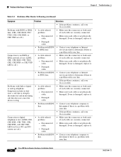
... lost . (LINE, CH1, CH1 RXD, CH1 TXD, CH2, CH2 RXD, and CH2 TXD LEDs on Cisco 801 and 803 routers are securely connected. • Make sure each cable is damaged, replace it . - If one is off.) • A cable-related problem: - Cisco 800 Series Routers Hardware Installation Guide 3-6 78-5373-04 Damaged cable. • Problem with ISDN • Contact your telephone company to digital telephone is lost . (LINE...
... lost . (LINE, CH1, CH1 RXD, CH1 TXD, CH2, CH2 RXD, and CH2 TXD LEDs on Cisco 801 and 803 routers are securely connected. • Make sure each cable is damaged, replace it . - If one is off.) • A cable-related problem: - Cisco 800 Series Routers Hardware Installation Guide 3-6 78-5373-04 Damaged cable. • Problem with ISDN • Contact your telephone company to digital telephone is lost . (LINE...
Hardware Installation Guide
Page 59
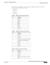
... • One stop bit Table B-8 ISDN S/T Connector Pinouts (RJ-45) Pin Function 1 Unused 2 Unused 3 TXD+ 4 RXD+ 5 RXD- 6 TXD- 7 Unused 8 Unused Table B-9 ISDN BRI U Connector Pinouts (RJ-45) Pin Function 1 Unused 2 Unused 3 Unused 4 U interface network connection (Tip) 5 U interface network connection (Ring) 6 Unused 7 Unused 8 Unused Table B-10 IDSL Connector Pinouts (RJ-45) Pin Function 1 Unused 2 Unused 3 Unused 4 IDSL interface network connection (Tip) Cisco 800 Series Routers Hardware Installation Guide B-5
... • One stop bit Table B-8 ISDN S/T Connector Pinouts (RJ-45) Pin Function 1 Unused 2 Unused 3 TXD+ 4 RXD+ 5 RXD- 6 TXD- 7 Unused 8 Unused Table B-9 ISDN BRI U Connector Pinouts (RJ-45) Pin Function 1 Unused 2 Unused 3 Unused 4 U interface network connection (Tip) 5 U interface network connection (Ring) 6 Unused 7 Unused 8 Unused Table B-10 IDSL Connector Pinouts (RJ-45) Pin Function 1 Unused 2 Unused 3 Unused 4 IDSL interface network connection (Tip) Cisco 800 Series Routers Hardware Installation Guide B-5
Hardware Installation Guide
Page 68
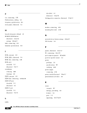
... to 2-13 ISDN S/T port described 1-2 illustrated 1-5 ISDN U port described 1-2 illustrated 1-5, 1-6 L LEDs IN-2 Cisco 800 Series Routers Hardware Installation Guide described 1-7 illustrated 1-3 to 1-6 locking power connector, illustrated 1-4 to 1-7 M modem, connecting 2-15 mounting the router 2-18 N network device button settings 2-6 to 2-7 NT1 feature 1-2 P panels, illustrated 1-4 to 1-7 PC, connecting 2-9, 2-17 port connector pinouts B-2 to B-6 ports for specific routers 1-3 power problems 3-2 specifications B-1 verifying 2-20 power supply connecting 2-18 power switch illustrated 1-4 to...
... to 2-13 ISDN S/T port described 1-2 illustrated 1-5 ISDN U port described 1-2 illustrated 1-5, 1-6 L LEDs IN-2 Cisco 800 Series Routers Hardware Installation Guide described 1-7 illustrated 1-3 to 1-6 locking power connector, illustrated 1-4 to 1-7 M modem, connecting 2-15 mounting the router 2-18 N network device button settings 2-6 to 2-7 NT1 feature 1-2 P panels, illustrated 1-4 to 1-7 PC, connecting 2-9, 2-17 port connector pinouts B-2 to B-6 ports for specific routers 1-3 power problems 3-2 specifications B-1 verifying 2-20 power supply connecting 2-18 power switch illustrated 1-4 to...

Hardware Installation Guide
Page 69
... router 2-4, ?? Index S S/T interface A-1 safety warnings 2-2 server, connecting 2-9 settings, network devices 2-6 to 2-7 specifications cabling B-6 system B-1 startup problems 3-2 T table mounting 2-18 telephone connecting 2-14, 2-15 ports described 1-2 illustrated 1-5, 1-6 temperature specifications B-1 terminal, connecting 2-17 TO HUB/TO PC button illustrated 1-6 to 1-7 settings 2-6 to 2-20 warnings, installation 2-2 weight specifications B-1 workstation, connecting 2-9 U U interface A-1 United Kingdom master sockets 2-16 78-5373-04 Cisco 800 Series Routers Hardware Installation Guide...
... router 2-4, ?? Index S S/T interface A-1 safety warnings 2-2 server, connecting 2-9 settings, network devices 2-6 to 2-7 specifications cabling B-6 system B-1 startup problems 3-2 T table mounting 2-18 telephone connecting 2-14, 2-15 ports described 1-2 illustrated 1-5, 1-6 temperature specifications B-1 terminal, connecting 2-17 TO HUB/TO PC button illustrated 1-6 to 1-7 settings 2-6 to 2-20 warnings, installation 2-2 weight specifications B-1 workstation, connecting 2-9 U U interface A-1 United Kingdom master sockets 2-16 78-5373-04 Cisco 800 Series Routers Hardware Installation Guide...

