Hardware Installation Guide
Page 4
...23 Cisco RPS Connector 1-23 Console Port 1-24 Management Options 1-24 Installation 2-1 Preparing for Installation 2-1 Warnings 2-1 Installation Guidelines 2-4 Verifying Package Contents 2-5 Verifying Switch Operation 2-6 Installing the Switch 2-7 Installing the Switch in a Rack 2-7 Attaching the Brackets to the Switch 2-8 Mounting the Switch ...Switch on a Table, Shelf, or Desk 2-17 Installing the Switch on a Wall 2-17 Attaching the Brackets to the Switch 2-17 Attaching the RPS Connector Cover 2-18 Mounting the Switch to a Wall 2-18 Installing the Optional AC Ground Kit for Catalyst 2950 Switches...
...23 Cisco RPS Connector 1-23 Console Port 1-24 Management Options 1-24 Installation 2-1 Preparing for Installation 2-1 Warnings 2-1 Installation Guidelines 2-4 Verifying Package Contents 2-5 Verifying Switch Operation 2-6 Installing the Switch 2-7 Installing the Switch in a Rack 2-7 Attaching the Brackets to the Switch 2-8 Mounting the Switch ...Switch on a Table, Shelf, or Desk 2-17 Installing the Switch on a Wall 2-17 Attaching the Brackets to the Switch 2-17 Attaching the RPS Connector Cover 2-18 Mounting the Switch to a Wall 2-18 Installing the Optional AC Ground Kit for Catalyst 2950 Switches...
Hardware Installation Guide
Page 18
... who hold valid Cisco service contracts, the Cisco Technical Assistance Center (TAC) provides 24-hour, award-winning technical support services, online and over the phone. On the Cisco Documentation home page, click Feedback at this URL: http://tools.cisco.com/RPF/register/register...solution. If you describe your document or by telephone. xviii Catalyst 2950 Switch Hardware Installation Guide OL-6156-01 Obtaining Technical Assistance Preface Documentation Feedback You can submit comments electronically on the Cisco TAC website requires a Cisco.com user ID and password.
... who hold valid Cisco service contracts, the Cisco Technical Assistance Center (TAC) provides 24-hour, award-winning technical support services, online and over the phone. On the Cisco Documentation home page, click Feedback at this URL: http://tools.cisco.com/RPF/register/register...solution. If you describe your document or by telephone. xviii Catalyst 2950 Switch Hardware Installation Guide OL-6156-01 Obtaining Technical Assistance Preface Documentation Feedback You can submit comments electronically on the Cisco TAC website requires a Cisco.com user ID and password.
Hardware Installation Guide
Page 21
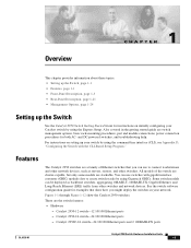
...." Catalyst 2950C-24 switch-24 10/100 Ethernet ports and 2 100BASE-FX ports OL-6156-01 Catalyst 2950 Switch Hardware Installation Guide 1-1 For instructions on initially configuring your Catalyst switch by using the Express Setup. You can be deployed as servers, routers, and other switches and network devices. Catalyst 2950-12 switch-12 10/100 Ethernet ports - Also covered in your network. These are stackable...
...." Catalyst 2950C-24 switch-24 10/100 Ethernet ports and 2 100BASE-FX ports OL-6156-01 Catalyst 2950 Switch Hardware Installation Guide 1-1 For instructions on initially configuring your Catalyst switch by using the Express Setup. You can be deployed as servers, routers, and other switches and network devices. Catalyst 2950-12 switch-12 10/100 Ethernet ports - Also covered in your network. These are stackable...

Hardware Installation Guide
Page 22
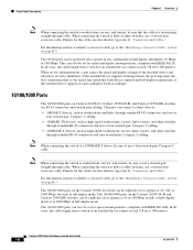
... then forwards the packet to the destination port Catalyst 2950 Switch Hardware Installation Guide 1-2 OL-6156-01 Catalyst 2950SX-24 switch-24 10/100 Ethernet ports and 2 1000BASE-SX ports - Features Chapter 1 Overview - Catalyst 2950G-24-EI-24 10/100 Ethernet ports and 2 GBIC module slots - Supports 8192 MAC addresses - Catalyst 2950ST-24 LRE 997 switch-24 LRE ports, 2 10/100/1000 Ethernet ports...
... then forwards the packet to the destination port Catalyst 2950 Switch Hardware Installation Guide 1-2 OL-6156-01 Catalyst 2950SX-24 switch-24 10/100 Ethernet ports and 2 1000BASE-SX ports - Features Chapter 1 Overview - Catalyst 2950G-24-EI-24 10/100 Ethernet ports and 2 GBIC module slots - Supports 8192 MAC addresses - Catalyst 2950ST-24 LRE 997 switch-24 LRE ports, 2 10/100/1000 Ethernet ports...

Hardware Installation Guide
Page 23
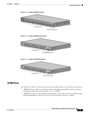
... 10x 11x 10Base-T / 100Base-TX 12x 10/100 ports Catalyst 2950 SERIES OL-6156-01 Catalyst 2950 Switch Hardware Installation Guide 1-3 Connection for an optional Cisco RPS 300 redundant power system (RPS) that uses AC input and supplies DC output to the switch - On the Catalyst 2950ST-24 LRE 997 switch, the front panel contains a DC power connector (also referred...
... 10x 11x 10Base-T / 100Base-TX 12x 10/100 ports Catalyst 2950 SERIES OL-6156-01 Catalyst 2950 Switch Hardware Installation Guide 1-3 Connection for an optional Cisco RPS 300 redundant power system (RPS) that uses AC input and supplies DC output to the switch - On the Catalyst 2950ST-24 LRE 997 switch, the front panel contains a DC power connector (also referred...

Hardware Installation Guide
Page 24
Front-Panel Description Figure 1-2 Catalyst 2950-24 Switch SYST RPS STAT UTIL DUPLX SPEED MODE 1 2 3 4x 5x 6x 7x 8x 9x 10x 11x 10Base-T / 100Base-TX 12x 13x 14x 15x 16x 17x 18x 19x 20x 21x 22x 23x Catalyst 2950 SERIES 24x 10/100 ports Figure 1-3 Catalyst 2950C-24 Switch SYST RPS STAT UTIL DUPLX SPEED MODE 1x 2x 3x 4x...
Front-Panel Description Figure 1-2 Catalyst 2950-24 Switch SYST RPS STAT UTIL DUPLX SPEED MODE 1 2 3 4x 5x 6x 7x 8x 9x 10x 11x 10Base-T / 100Base-TX 12x 13x 14x 15x 16x 17x 18x 19x 20x 21x 22x 23x Catalyst 2950 SERIES 24x 10/100 ports Figure 1-3 Catalyst 2950C-24 Switch SYST RPS STAT UTIL DUPLX SPEED MODE 1x 2x 3x 4x...
Hardware Installation Guide
Page 25
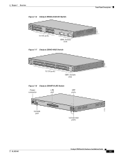
... 8 9 10 11 12 11X 2X 12X 13X 13 14 15 16 17 18 19 20 21 22 23 24 23X 14X 24X 10/100 ports 1 Catalyst 2950 SERIES 2 GBIC module slots Figure 1-7 Catalyst 2950G-48-EI Switch SYST RPS STAT UTIL DUPLX SPEED MODE 1 1X 2X 23 45 67 8 9 10 11 12 13 14 15... 16 17 15X 17X 18 19 20 21 22 23 24 25 26 27 28 29 30 31 32 16X...
... 8 9 10 11 12 11X 2X 12X 13X 13 14 15 16 17 18 19 20 21 22 23 24 23X 14X 24X 10/100 ports 1 Catalyst 2950 SERIES 2 GBIC module slots Figure 1-7 Catalyst 2950G-48-EI Switch SYST RPS STAT UTIL DUPLX SPEED MODE 1 1X 2X 23 45 67 8 9 10 11 12 13 14 15... 16 17 15X 17X 18 19 20 21 22 23 24 25 26 27 28 29 30 31 32 16X...
Hardware Installation Guide
Page 26
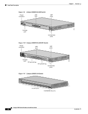
...RPS STAT SPEED CONSOLE 1 2 3 4 5 6 7 8 9 10 11 12 Console port 13 14 15 16 17 18 19 20 21 22 23 24 Catalyst 2950 SERIES LRE 1 2 1 2 10/100/1000 ports Figure 1-10 Catalyst 2950ST-24 LRE 997 Switch Power connector LRE port SFP ports - ++ A INPCUUTR:RE3N6T- B 72 V :2-1 A - SYST RPS STAT SPEED MODE CONSOLE 1 2 3 4 5 ...port DC ground lug 13 14 15 16 17 18 19 20 21 22 23 24 Catalyst 2950 SERIES LRE 997 1 2 1 2 DC ground lug 10/100/1000 ports Figure 1-11 Catalyst 2950SX-24 Switch SYST RPS STAT UTIL DUPLX SPEED MODE 1x 2x 3x 4x 5x 6x 7x ...
...RPS STAT SPEED CONSOLE 1 2 3 4 5 6 7 8 9 10 11 12 Console port 13 14 15 16 17 18 19 20 21 22 23 24 Catalyst 2950 SERIES LRE 1 2 1 2 10/100/1000 ports Figure 1-10 Catalyst 2950ST-24 LRE 997 Switch Power connector LRE port SFP ports - ++ A INPCUUTR:RE3N6T- B 72 V :2-1 A - SYST RPS STAT SPEED MODE CONSOLE 1 2 3 4 5 ...port DC ground lug 13 14 15 16 17 18 19 20 21 22 23 24 Catalyst 2950 SERIES LRE 997 1 2 1 2 DC ground lug 10/100/1000 ports Figure 1-11 Catalyst 2950SX-24 Switch SYST RPS STAT UTIL DUPLX SPEED MODE 1x 2x 3x 4x 5x 6x 7x ...
Hardware Installation Guide
Page 27
... devices: • 10BASE-T devices, such as high-speed workstations, servers, hubs, routers, and other switches, through standard RJ-45 connectors and two twisted-pair cabling. OL-6156-01 Catalyst 2950 Switch Hardware Installation Guide 1-7 Chapter 1 Overview Figure 1-12 Catalyst 2950T-24 Switch Front-Panel Description 47337 SYST RPS STAT UTIL DUPLX SPEED MODE 1x 2x 3x 4x...
... devices: • 10BASE-T devices, such as high-speed workstations, servers, hubs, routers, and other switches, through standard RJ-45 connectors and two twisted-pair cabling. OL-6156-01 Catalyst 2950 Switch Hardware Installation Guide 1-7 Chapter 1 Overview Figure 1-12 Catalyst 2950T-24 Switch Front-Panel Description 47337 SYST RPS STAT UTIL DUPLX SPEED MODE 1x 2x 3x 4x...
Hardware Installation Guide
Page 28
... 1000BASE-T devices, such as high-speed workstations, servers, hubs, routers, and other switches, use a twisted-pair crossover cable. For information on Catalyst 2950T-24, Catalyst 2950T-48-SI, and Catalyst 2950 LRE switches use a twisted-pair straight-through cable. The ports can be set to hubs or... other switches, use a twisted-pair crossover cable. If the attached device supports ...
... 1000BASE-T devices, such as high-speed workstations, servers, hubs, routers, and other switches, use a twisted-pair crossover cable. For information on Catalyst 2950T-24, Catalyst 2950T-48-SI, and Catalyst 2950 LRE switches use a twisted-pair straight-through cable. The ports can be set to hubs or... other switches, use a twisted-pair crossover cable. If the attached device supports ...
Hardware Installation Guide
Page 29
... an attached device cannot exceed 1804 feet (550 meters). OL-6156-01 Catalyst 2950 Switch Hardware Installation Guide 1-9 See the "SFP Module Slots" section on a target device by using one of up to 24 Cisco LRE CPE devices through a plain old telephone service (POTS) splitter. In full-duplex mode, the cable length from a 100BASE-FX...
... an attached device cannot exceed 1804 feet (550 meters). OL-6156-01 Catalyst 2950 Switch Hardware Installation Guide 1-9 See the "SFP Module Slots" section on a target device by using one of up to 24 Cisco LRE CPE devices through a plain old telephone service (POTS) splitter. In full-duplex mode, the cable length from a 100BASE-FX...

Hardware Installation Guide
Page 33
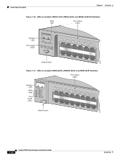
... the Catalyst 2950-12, 2950-24, 2950C-24, 2950SX-24, and 2950T-24 switches • Figure 1-16 for the Catalyst 2950G-12-EI, 2950G-24-EI, and 2950G-24-EI-DC switches • Figure 1-17 for the Catalyst 2950G-48-EI, Catalyst 2950SX-48-SI, and Catalyst 2950T-48-SI switches • Figure 1-18 for the Catalyst 2950ST-8 LRE and 2950ST-24 LRE switches • Figure 1-19 for the Catalyst 2950ST-24...
... the Catalyst 2950-12, 2950-24, 2950C-24, 2950SX-24, and 2950T-24 switches • Figure 1-16 for the Catalyst 2950G-12-EI, 2950G-24-EI, and 2950G-24-EI-DC switches • Figure 1-17 for the Catalyst 2950G-48-EI, Catalyst 2950SX-48-SI, and Catalyst 2950T-48-SI switches • Figure 1-18 for the Catalyst 2950ST-8 LRE and 2950ST-24 LRE switches • Figure 1-19 for the Catalyst 2950ST-24...
Hardware Installation Guide
Page 34
Front-Panel Description Chapter 1 Overview Figure 1-16 LEDs on Catalyst 2950G-12-EI, 2950G-24-EI, and 2950G-24-EI-DC Switches RPS LED Port status LEDs 65395 System LED Port mode LEDs SYST RPS STAT UTIL DUPLX SPEED MODE 1 1X 23 45 67 8 9 10 11 12 ...-EI, 2950SX-48-SI, and 2950T-48-SI Switches Port status LEDs System LED RPS LED Port mode LEDs SYST RPS STAT UTIL DUPLX SPEED MODE 1 1X 23 45 67 89 10 11 12 13 14 15 16 15X 2X 16X Mode button 65508 1-14 Catalyst 2950 Switch Hardware Installation Guide OL-6156-01
Front-Panel Description Chapter 1 Overview Figure 1-16 LEDs on Catalyst 2950G-12-EI, 2950G-24-EI, and 2950G-24-EI-DC Switches RPS LED Port status LEDs 65395 System LED Port mode LEDs SYST RPS STAT UTIL DUPLX SPEED MODE 1 1X 23 45 67 8 9 10 11 12 ...-EI, 2950SX-48-SI, and 2950T-48-SI Switches Port status LEDs System LED RPS LED Port mode LEDs SYST RPS STAT UTIL DUPLX SPEED MODE 1 1X 23 45 67 89 10 11 12 13 14 15 16 15X 2X 16X Mode button 65508 1-14 Catalyst 2950 Switch Hardware Installation Guide OL-6156-01

Hardware Installation Guide
Page 35
... SPEED MODE CONSOLE STAT LED Speed Mode LED button 1 2 3 4 5 6 7 8 9 10 11 12 89364 OL-6156-01 Catalyst 2950 Switch Hardware Installation Guide 1-15 Chapter 1 Overview Front-Panel Description Figure 1-18 LEDs on Catalyst 2950ST-8 LRE and 2950ST-24 LRE Switches System LED Redundant power system LED Port status LEDs 81187 110.00A-1/02R.75A/TA2I0N500G--26400HVZ...
... SPEED MODE CONSOLE STAT LED Speed Mode LED button 1 2 3 4 5 6 7 8 9 10 11 12 89364 OL-6156-01 Catalyst 2950 Switch Hardware Installation Guide 1-15 Chapter 1 Overview Front-Panel Description Figure 1-18 LEDs on Catalyst 2950ST-8 LRE and 2950ST-24 LRE Switches System LED Redundant power system LED Port status LEDs 81187 110.00A-1/02R.75A/TA2I0N500G--26400HVZ...

Hardware Installation Guide
Page 37
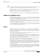
...10/100/1000 ports. 1. Table 1-7 explains how to Figure 1-24 for Non-LRE Switches Port Mode Color Meaning STAT (port status) Off No link. Solid green Link present. Alternating green-amber Link fault. A Catalyst 2950 LRE switch does not have a UTIL or a DUPLX LED. Table 1-6 explains... on a logarithmic scale. Amber The maximum backplane utilization since the switch was disabled by the switch. DUPLX Port duplex mode The port duplex mode: half duplex or full duplex. OL-6156-01 Catalyst 2950 Switch Hardware Installation Guide 1-17 Note If the current utilization exceeds the ...
...10/100/1000 ports. 1. Table 1-7 explains how to Figure 1-24 for Non-LRE Switches Port Mode Color Meaning STAT (port status) Off No link. Solid green Link present. Alternating green-amber Link fault. A Catalyst 2950 LRE switch does not have a UTIL or a DUPLX LED. Table 1-6 explains... on a logarithmic scale. Amber The maximum backplane utilization since the switch was disabled by the switch. DUPLX Port duplex mode The port duplex mode: half duplex or full duplex. OL-6156-01 Catalyst 2950 Switch Hardware Installation Guide 1-17 Note If the current utilization exceeds the ...
Hardware Installation Guide
Page 39
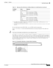
... of the total bandwidth. (See Figure 1-20 and Figure 1-21.) Figure 1-20 Bandwidth Utilization on a Catalyst 2950-12, 2950-24, 2950C-24, 2950SX-24, or 2950T-24 switch are green (no amber showing), the switch is active. 2. On an LRE switch, the LEDs for the LRE Switches (continued) Port Mode SPEED Color Meaning 10/100/1000 ports1 2 Off Port is operating at...
... of the total bandwidth. (See Figure 1-20 and Figure 1-21.) Figure 1-20 Bandwidth Utilization on a Catalyst 2950-12, 2950-24, 2950C-24, 2950SX-24, or 2950T-24 switch are green (no amber showing), the switch is active. 2. On an LRE switch, the LEDs for the LRE Switches (continued) Port Mode SPEED Color Meaning 10/100/1000 ports1 2 Off Port is operating at...
Hardware Installation Guide
Page 40
... using more than 25 but less than 25 percent of the total bandwidth. Front-Panel Description Chapter 1 Overview Figure 1-21 Bandwidth Utilization on Catalyst 2950-24, 2950C-24, 2950SX-24, and 2950T-24 Switches SYST RPS STAT UTIL DUPLX SPEED MODE 1x 2x 3x 4x 5x 6x 7x 8x 10Base-T / 100Base-TX 9x 10x 11x 12x 13x 14x...
... using more than 25 but less than 25 percent of the total bandwidth. Front-Panel Description Chapter 1 Overview Figure 1-21 Bandwidth Utilization on Catalyst 2950-24, 2950C-24, 2950SX-24, and 2950T-24 Switches SYST RPS STAT UTIL DUPLX SPEED MODE 1x 2x 3x 4x 5x 6x 7x 8x 10Base-T / 100Base-TX 9x 10x 11x 12x 13x 14x...
Hardware Installation Guide
Page 53
... Use these instructions to install the switch in a rack: Warning To prevent bodily injury when mounting or servicing this unit in a partially filled rack, load the rack from Cisco (part number RCKMNT-1RU=). Mounting the Switch in a 19-, 23-, or 24-inch rack, follow these steps: 1. OL-6156-01 Catalyst 2950 Switch Hardware Installation Guide 2-7 Statement 1006...
... Use these instructions to install the switch in a rack: Warning To prevent bodily injury when mounting or servicing this unit in a partially filled rack, load the rack from Cisco (part number RCKMNT-1RU=). Mounting the Switch in a 19-, 23-, or 24-inch rack, follow these steps: 1. OL-6156-01 Catalyst 2950 Switch Hardware Installation Guide 2-7 Statement 1006...
Hardware Installation Guide
Page 74
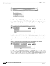
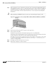
... loops. This process takes about 30 seconds, and then the LED turns green. Figure 2-35 Connecting to a Port on Catalyst 2950-12, 2950-24, 2950C-24, 2950SX-24, and 2950T-24 Switches SYST RPS STAT UTIL DUPLX SPEED MODE 1x 2x 3x 4x 5x 45576 Step 2 Step 3 Step 4 Step 5 Insert ...the other cable end in a front-panel RJ-45 connector. Figure 2-35 shows the Catalyst 2950-12, 2950-24, 2950C-24, 2950SX-24, and 2950T-24 switch as an example. Connecting to 10/100 and 10/100/1000 Ports Chapter 2 Installation Step 1 When connecting to servers, workstations...
... loops. This process takes about 30 seconds, and then the LED turns green. Figure 2-35 Connecting to a Port on Catalyst 2950-12, 2950-24, 2950C-24, 2950SX-24, and 2950T-24 Switches SYST RPS STAT UTIL DUPLX SPEED MODE 1x 2x 3x 4x 5x 45576 Step 2 Step 3 Step 4 Step 5 Insert ...the other cable end in a front-panel RJ-45 connector. Figure 2-35 shows the Catalyst 2950-12, 2950-24, 2950C-24, 2950SX-24, and 2950T-24 switch as an example. Connecting to 10/100 and 10/100/1000 Ports Chapter 2 Installation Step 1 When connecting to servers, workstations...

Hardware Installation Guide
Page 91
...)1 AC input voltage DC input voltages for the Cisco RPS2 300 Redundant Power System 100 to 127/200 to 240 VAC (autoranging) 50 to 15,000 ft (4570 m) 84 in . (4.36 x 44.45 x 24.18 cm) 1. Table A-1 Technical Specifications for Catalyst 2950-12, 2950-24, 2950C-24, 2950SX-24, and 2950T-24 Switches Environmental Ranges Operating temperature 32 to 113°...
...)1 AC input voltage DC input voltages for the Cisco RPS2 300 Redundant Power System 100 to 127/200 to 240 VAC (autoranging) 50 to 15,000 ft (4570 m) 84 in . (4.36 x 44.45 x 24.18 cm) 1. Table A-1 Technical Specifications for Catalyst 2950-12, 2950-24, 2950C-24, 2950SX-24, and 2950T-24 Switches Environmental Ranges Operating temperature 32 to 113°...


