Hardware Installation Guide
Page 21
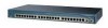
... use to create switch stacks by using the command-line interface (CLI), see Appendix D, "Configuring the Switch with gigabit interface converter (GBIC) module slots to connect workstations and other network devices, such as backbone switches, aggregating 10BASE-T, 100BASE-TX, Gigabit Ethernet, and Long-Reach Ethernet (LRE) traffic from other switches. Figure 1-1 through Figure 1-12 show how you can be deployed as servers, routers, and other switches and network devices. Catalyst 2950-24 switch-24 10/100 Ethernet ports - For instructions on initially configuring your network...
... use to create switch stacks by using the command-line interface (CLI), see Appendix D, "Configuring the Switch with gigabit interface converter (GBIC) module slots to connect workstations and other network devices, such as backbone switches, aggregating 10BASE-T, 100BASE-TX, Gigabit Ethernet, and Long-Reach Ethernet (LRE) traffic from other switches. Figure 1-1 through Figure 1-12 show how you can be deployed as servers, routers, and other switches and network devices. Catalyst 2950-24 switch-24 10/100 Ethernet ports - For instructions on initially configuring your network...

Hardware Installation Guide
Page 22
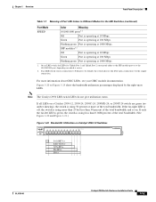
... then forwards the packet to the destination port Catalyst 2950 Switch Hardware Installation Guide 1-2 OL-6156-01 For 10/100/1000 ports on the Catalyst 2950T-48-SI and 2950 LRE switches, autonegotiates the speed and duplex setting when operating at 1000 Mbps, it supports only full-duplex mode. - Catalyst 2950T-48-SI switch-48 10/100 Ethernet ports and 2 10/100/1000 Ethernet ports - On Catalyst 2950G-12-EI, 2950G-24-EI, 2950G-24-EI...
... then forwards the packet to the destination port Catalyst 2950 Switch Hardware Installation Guide 1-2 OL-6156-01 For 10/100/1000 ports on the Catalyst 2950T-48-SI and 2950 LRE switches, autonegotiates the speed and duplex setting when operating at 1000 Mbps, it supports only full-duplex mode. - Catalyst 2950T-48-SI switch-48 10/100 Ethernet ports and 2 10/100/1000 Ethernet ports - On Catalyst 2950G-12-EI, 2950G-24-EI, 2950G-24-EI...
Hardware Installation Guide
Page 28
... as high-speed workstations, servers, hubs, routers, and other switches, through cable. Catalyst 2950 Switch Hardware Installation Guide 1-8 OL-6156-01 If the attached device supports autonegotiation, the port negotiates the best connection (that both devices support and full-duplex transmission, if the attached device supports it) and configures itself accordingly. 10/100/1000 Ports The 10/100/1000 ports on Catalyst 2950T-24, Catalyst 2950T-48-SI, and Catalyst 2950 LRE switches use RJ-45...
... as high-speed workstations, servers, hubs, routers, and other switches, through cable. Catalyst 2950 Switch Hardware Installation Guide 1-8 OL-6156-01 If the attached device supports autonegotiation, the port negotiates the best connection (that both devices support and full-duplex transmission, if the attached device supports it) and configures itself accordingly. 10/100/1000 Ports The 10/100/1000 ports on Catalyst 2950T-24, Catalyst 2950T-48-SI, and Catalyst 2950 LRE switches use RJ-45...
Hardware Installation Guide
Page 29
.../100/1000 port and a fiber-optic SFP module slot, respectively. The splitter routes LRE data (high-frequency) and voice (low-frequency) traffic from a 100BASE-FX port on a switch to an SC or ST port on a switch to private telephone networks and the PSTN. You can use 50/125- Within each logical port, you need. Use the Cisco part numbers in Table 2-1 on a Catalyst 2950ST-24 LRE 997 switch. The default mode for the Cisco LRE...
.../100/1000 port and a fiber-optic SFP module slot, respectively. The splitter routes LRE data (high-frequency) and voice (low-frequency) traffic from a 100BASE-FX port on a switch to an SC or ST port on a switch to private telephone networks and the PSTN. You can use 50/125- Within each logical port, you need. Use the Cisco part numbers in Table 2-1 on a Catalyst 2950ST-24 LRE 997 switch. The default mode for the Cisco LRE...

Hardware Installation Guide
Page 30
... splitters, contact your GBIC module documentation. 1-10 Catalyst 2950 Switch Hardware Installation Guide OL-6156-01 If a connection to a telephone network is not required, a splitter is inserted in a stack configuration) to -GigaStack GBIC connection cannot exceed 3 feet (1 meter). Front-Panel Description Chapter 1 Overview For limitations and restrictions when you are using a non-Cisco approved CWDM GBIC module, remove the module from the switch, and replace it with POTS Splitters...
... splitters, contact your GBIC module documentation. 1-10 Catalyst 2950 Switch Hardware Installation Guide OL-6156-01 If a connection to a telephone network is not required, a splitter is inserted in a stack configuration) to -GigaStack GBIC connection cannot exceed 3 feet (1 meter). Front-Panel Description Chapter 1 Overview For limitations and restrictions when you are using a non-Cisco approved CWDM GBIC module, remove the module from the switch, and replace it with POTS Splitters...

Hardware Installation Guide
Page 31
... specifications on Uplink Port 1. The Catalyst 2950 LRE switch has four physical input ports that the SFP module port does not take precedence over the 10/100/1000 port. Note By using the media-type {sfp | rj45 | auto-select} interface configuration command at the CLI, you can use fiber-optic cables with RJ-45 connectors to connect to 1550 nanometers (nm). For more information about the media-type {sfp | rj45 | auto-select} command, see the switch command reference. The SFP modules support...
... specifications on Uplink Port 1. The Catalyst 2950 LRE switch has four physical input ports that the SFP module port does not take precedence over the 10/100/1000 port. Note By using the media-type {sfp | rj45 | auto-select} interface configuration command at the CLI, you can use fiber-optic cables with RJ-45 connectors to connect to 1550 nanometers (nm). For more information about the media-type {sfp | rj45 | auto-select} command, see the switch command reference. The SFP modules support...

Hardware Installation Guide
Page 32
When using a non-Cisco approved SFP module, remove the module from the switch, and replace it with a Cisco-approved module. When the fiber-optic cable span is invalid, the switch places the interface in the switch, the switch software reads the EEPROM to avoid overloading the receiver. For more information about these SFP modules, see your SFP module documentation. 1-12 Catalyst 2950 Switch Hardware Installation Guide OL-6156-01 If the serial number, the vendor name or ID, security code, or CRC...
When using a non-Cisco approved SFP module, remove the module from the switch, and replace it with a Cisco-approved module. When the fiber-optic cable span is invalid, the switch places the interface in the switch, the switch software reads the EEPROM to avoid overloading the receiver. For more information about these SFP modules, see your SFP module documentation. 1-12 Catalyst 2950 Switch Hardware Installation Guide OL-6156-01 If the serial number, the vendor name or ID, security code, or CRC...

Hardware Installation Guide
Page 33
... switch software configuration guide describes how to use the command-line interface (CLI) to configure and to monitor switch activity and performance. The locations and numbers of the Mode button that you use to select the port mode also varies by model. Figure 1-15 LEDs on Catalyst 2950-12, 2950-24, 2950C-24, 2950SX-24, and 2950T-24 Switches RPS LED Port status LEDs System LED Port mode LEDs SYST RPS STAT UTIL DUPLX SPEED MODE Mode button 1x 2x 3x 4x 5x 6x 52918 OL-6156-01 Catalyst 2950 Switch Hardware Installation Guide...
... switch software configuration guide describes how to use the command-line interface (CLI) to configure and to monitor switch activity and performance. The locations and numbers of the Mode button that you use to select the port mode also varies by model. Figure 1-15 LEDs on Catalyst 2950-12, 2950-24, 2950C-24, 2950SX-24, and 2950T-24 Switches RPS LED Port status LEDs System LED Port mode LEDs SYST RPS STAT UTIL DUPLX SPEED MODE Mode button 1x 2x 3x 4x 5x 6x 52918 OL-6156-01 Catalyst 2950 Switch Hardware Installation Guide...

Hardware Installation Guide
Page 37
.... Port is not forwarding. Error frames can affect connectivity, and errors such as excessive collisions, CRC errors, and alignment and jabber errors are off when the MODE is reconfigured, the port LED can remain amber for up to SPEED. OL-6156-01 Catalyst 2950 Switch Hardware Installation Guide 1-17 Flashing green Activity. Solid amber Port is sending or receiving data. DUPLX Off Port is operating in use by management, an address violation, or Spanning Tree Protocol (STP). Note After a port is set...
.... Port is not forwarding. Error frames can affect connectivity, and errors such as excessive collisions, CRC errors, and alignment and jabber errors are off when the MODE is reconfigured, the port LED can remain amber for up to SPEED. OL-6156-01 Catalyst 2950 Switch Hardware Installation Guide 1-17 Flashing green Activity. Solid amber Port is sending or receiving data. DUPLX Off Port is operating in use by management, an address violation, or Spanning Tree Protocol (STP). Note After a port is set...
Hardware Installation Guide
Page 39
...-01 Catalyst 2950 Switch Hardware Installation Guide 1-19 If all LEDs on a Catalyst 2950-12, 2950-24, 2950C-24, 2950SX-24, or 2950T-24 switch are green (no amber showing), the switch is using less than 50 percent of the total bandwidth, and so on which is active. 2. Green Port is operating at 1000 Mbps 1. Flashing green Port is operating at 10 Mbps. On an LRE switch, the LEDs for the LRE Switches (continued) Port Mode SPEED Color...
...-01 Catalyst 2950 Switch Hardware Installation Guide 1-19 If all LEDs on a Catalyst 2950-12, 2950-24, 2950C-24, 2950SX-24, or 2950T-24 switch are green (no amber showing), the switch is using less than 50 percent of the total bandwidth, and so on which is active. 2. Green Port is operating at 1000 Mbps 1. Flashing green Port is operating at 10 Mbps. On an LRE switch, the LEDs for the LRE Switches (continued) Port Mode SPEED Color...
Hardware Installation Guide
Page 44
... standalone switches. For console-port and adapter-pinout information, see the switch command reference. To launch the Device Manager, enter the switch IP address in the switch memory, to -DB-9 adapter cable. You can manage switches by using command-line entries. For setup instructions that use the CLI, go to Appendix D, "Configuring the Switch with that came with your CiscoView application. • SNMP network management You can use the CiscoView device-management application to perform basic switch configuration and monitoring. The device manager...
... standalone switches. For console-port and adapter-pinout information, see the switch command reference. To launch the Device Manager, enter the switch IP address in the switch memory, to -DB-9 adapter cable. You can manage switches by using command-line entries. For setup instructions that use the CLI, go to Appendix D, "Configuring the Switch with that came with your CiscoView application. • SNMP network management You can use the CiscoView device-management application to perform basic switch configuration and monitoring. The device manager...

Hardware Installation Guide
Page 52
... to connect a PC to the switch console port and to the switch - One cable guide and one of the mounting brackets - One ground lug - After a successful POST, follow these items: - Verifying Switch Operation Chapter 2 Installation - If a switch fails POST, the System LED turns amber. Four number-8 Phillips truss-head screws for attaching the cable guide to one black Phillips machine screw for attaching the brackets to a rack - Catalyst 2950 Switch Hardware Installation Guide 2-6 OL...
... to connect a PC to the switch console port and to the switch - One cable guide and one of the mounting brackets - One ground lug - After a successful POST, follow these items: - Verifying Switch Operation Chapter 2 Installation - If a switch fails POST, the System LED turns amber. Four number-8 Phillips truss-head screws for attaching the cable guide to one black Phillips machine screw for attaching the brackets to a rack - Catalyst 2950 Switch Hardware Installation Guide 2-6 OL...
Hardware Installation Guide
Page 65
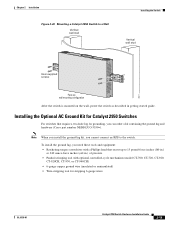
... a kit containing the ground lug and hardware (Cisco part number NEBS-LUG-3550=). To install the ground lug, you need these tools and equipment: • Ratcheting torque screwdriver with optional controlled-cycle mechanism (model CT-700, CT-720, CT-920,...Installing the Switch Vertical wall stud Catalyst 2950 SERIES LRE 2A 2B 13 14 15 16 17 18 19 20 21 22 23 24 9 10 11 12 1.01A/000.-51A275/02-R06A00-TI2HN4ZM0GVO~DE SPEESDTAT RPS SYST CONSOLE 1 2 3 4 5 6 7 8 86317 User-supplied screws Face up wall mounting configuration After the switch is mounted on the wall, power the switch...
... a kit containing the ground lug and hardware (Cisco part number NEBS-LUG-3550=). To install the ground lug, you need these tools and equipment: • Ratcheting torque screwdriver with optional controlled-cycle mechanism (model CT-700, CT-720, CT-920,...Installing the Switch Vertical wall stud Catalyst 2950 SERIES LRE 2A 2B 13 14 15 16 17 18 19 20 21 22 23 24 9 10 11 12 1.01A/000.-51A275/02-R06A00-TI2HN4ZM0GVO~DE SPEESDTAT RPS SYST CONSOLE 1 2 3 4 5 6 7 8 86317 User-supplied screws Face up wall mounting configuration After the switch is mounted on the wall, power the switch...
Hardware Installation Guide
Page 69
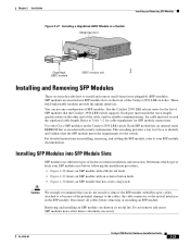
... the switch. Each port must match the wave-length specifications on the Catalyst 2950 LRE switch. These field-replaceable modules provide the uplink interfaces. Determine which type of SFP modules that the SFP module meets the requirements for the list of latch your SFP module documentation. Use only Cisco SFP modules on the other end of latches for reliable communications, the cable must not exceed the stipulated cable length. OL-6156-01 Catalyst 2950 Switch Hardware Installation Guide 2-23...
... the switch. Each port must match the wave-length specifications on the Catalyst 2950 LRE switch. These field-replaceable modules provide the uplink interfaces. Determine which type of SFP modules that the SFP module meets the requirements for the list of latch your SFP module documentation. Use only Cisco SFP modules on the other end of latches for reliable communications, the cable must not exceed the stipulated cable length. OL-6156-01 Catalyst 2950 Switch Hardware Installation Guide 2-23...
Hardware Installation Guide
Page 76
... telephone services are supported by the LRE switches, see the Installation and Warranty Notes for loops. See Chapter 3, "Troubleshooting," for solutions to an LRE Port Chapter 2 Installation Step 5 Step 6 The LED turns amber while STP discovers the network topology and searches for the Cisco LRE 48 POTS Splitter. For information about homologated POTS splitters, contact your Catalyst 2950ST-8 LRE or Catalyst 2950ST-24 LRE switch. Connecting to cabling problems. Reconfigure...
... telephone services are supported by the LRE switches, see the Installation and Warranty Notes for loops. See Chapter 3, "Troubleshooting," for solutions to an LRE Port Chapter 2 Installation Step 5 Step 6 The LED turns amber while STP discovers the network topology and searches for the Cisco LRE 48 POTS Splitter. For information about homologated POTS splitters, contact your Catalyst 2950ST-8 LRE or Catalyst 2950ST-24 LRE switch. Connecting to cabling problems. Reconfigure...

Hardware Installation Guide
Page 86
... the switch software configuration guide. 2-40 Catalyst 2950 Switch Hardware Installation Guide OL-6156-01 If the default configuration is described in your network through a web browser. Through this GUI, you can configure and monitor a switch cluster or an individual switch. • Use the CLI from anywhere in the Getting Started with Cisco Network Assistant guide. For more information. For setup instructions that offers quick configuration and monitoring. For information about starting up the switch, see the device manager...
... the switch software configuration guide. 2-40 Catalyst 2950 Switch Hardware Installation Guide OL-6156-01 If the default configuration is described in your network through a web browser. Through this GUI, you can configure and monitor a switch cluster or an individual switch. • Use the CLI from anywhere in the Getting Started with Cisco Network Assistant guide. For more information. For setup instructions that offers quick configuration and monitoring. For information about starting up the switch, see the device manager...

Hardware Installation Guide
Page 120
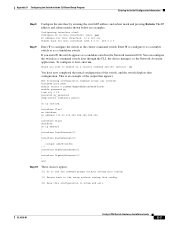
... can access the CLI on a configured or unconfigured switch by using the CLI, see the switch command reference for the switch, use the write memory privileged EXEC command to save it to the serial port on your PC or workstation and accessing the switch through the console port, follow these sections in Express Setup mode, open a Telnet session to a Power Source" section on page D-5 • "Entering the Initial Configuration Information" section on page D-5 Catalyst 2950 Switch Hardware Installation Guide...
... can access the CLI on a configured or unconfigured switch by using the CLI, see the switch command reference for the switch, use the write memory privileged EXEC command to save it to the serial port on your PC or workstation and accessing the switch through the console port, follow these sections in Express Setup mode, open a Telnet session to a Power Source" section on page D-5 • "Entering the Initial Configuration Information" section on page D-5 Catalyst 2950 Switch Hardware Installation Guide...
Hardware Installation Guide
Page 125
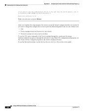
... in the Network Assistant GUI. This is an example of the switch, and the switch displays that appears: The following configuration command script was created: hostname host_name enable secret 5 $1$Max7$Qgr9eXBhtcBJw3KK7bc850 enable password my line vty 0 15 password my_password snmp-server community public ! interface GigabitEthernet0/1 ! interface GigabitEthernet0/2 ! OL-6156-01 Catalyst 2950 Switch Hardware Installation Guide D-7 Enter N to enable as a standalone switch. interface Vlan2 shutdown no . You can configure the switch as the cluster command switch. no shutdown...
... in the Network Assistant GUI. This is an example of the switch, and the switch displays that appears: The following configuration command script was created: hostname host_name enable secret 5 $1$Max7$Qgr9eXBhtcBJw3KK7bc850 enable password my line vty 0 15 password my_password snmp-server community public ! interface GigabitEthernet0/1 ! interface GigabitEthernet0/2 ! OL-6156-01 Catalyst 2950 Switch Hardware Installation Guide D-7 Enter N to enable as a standalone switch. interface Vlan2 shutdown no . You can configure the switch as the cluster command switch. no shutdown...
Hardware Installation Guide
Page 126
... press Return. After you complete the setup program, the switch can run the default configuration that you want to save the configuration and use the Network Assistant, see the switch software configuration guide or the switch command reference. To use it the next time the switch reboots, save it in nonvolatile RAM (NVRAM) by using Telnet. For configuration information, see the Getting Started with the CLI-Based Setup Program If you created. Catalyst 2950 Switch Hardware Installation Guide D-8 OL-6156-01
... press Return. After you complete the setup program, the switch can run the default configuration that you want to save the configuration and use the Network Assistant, see the switch software configuration guide or the switch command reference. To use it the next time the switch reboots, save it in nonvolatile RAM (NVRAM) by using Telnet. For configuration information, see the Getting Started with the CLI-Based Setup Program If you created. Catalyst 2950 Switch Hardware Installation Guide D-8 OL-6156-01

Hardware Installation Guide
Page 131
... 3-34 connection guidelines 3-30 described 2-9 illustrated 2-5 LEDs 2-17, 2-18 problems, solving 4-4 See also RJ-21 connector LRE uplink ports 2-9 M management options 2-24 Mode button 2-16 mounting desk 3-17 rack 3-7 to 3-16 shelf 3-17 table 3-17 mounting brackets, attaching 3-8 to 3-15, 3-17 MT-RJ connector B-4 OL-6156-01 Index N Network Assistant getting started guide xvi to configure switch 3-40 viewing LEDs 2-13 network configuration examples 2-1 Network Manager described 2-24 noise, electrical 3-5 notes, defined ix O obtaining documentation xvii...
... 3-34 connection guidelines 3-30 described 2-9 illustrated 2-5 LEDs 2-17, 2-18 problems, solving 4-4 See also RJ-21 connector LRE uplink ports 2-9 M management options 2-24 Mode button 2-16 mounting desk 3-17 rack 3-7 to 3-16 shelf 3-17 table 3-17 mounting brackets, attaching 3-8 to 3-15, 3-17 MT-RJ connector B-4 OL-6156-01 Index N Network Assistant getting started guide xvi to configure switch 3-40 viewing LEDs 2-13 network configuration examples 2-1 Network Manager described 2-24 noise, electrical 3-5 notes, defined ix O obtaining documentation xvii...


