
Hardware Installation Guide
Page 22
..., autonegotiates the speed and duplex settings - On Catalyst 2950G-12-EI, 2950G-24-EI, 2950G-24-EI-DC, and 2950G-48-EI switches, support for the Catalyst 2950 LRE switches. - Checks for errors on the Catalyst 2950T-24 switch, autonegotiates the speed and supports only full-duplex mode - Features Chapter 1 Overview - Catalyst 2950ST-24 LRE switch-24 LRE ports, 2 10/100/1000 Ethernet ports...
..., autonegotiates the speed and duplex settings - On Catalyst 2950G-12-EI, 2950G-24-EI, 2950G-24-EI-DC, and 2950G-48-EI switches, support for the Catalyst 2950 LRE switches. - Checks for errors on the Catalyst 2950T-24 switch, autonegotiates the speed and supports only full-duplex mode - Features Chapter 1 Overview - Catalyst 2950ST-24 LRE switch-24 LRE ports, 2 10/100/1000 Ethernet ports...
Hardware Installation Guide
Page 27
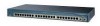
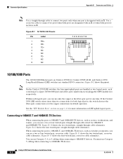
...8226; 10BASE-T devices, such as high-speed workstations, servers, hubs, routers, and other switches, through standard RJ-45 connectors and two twisted-pair cabling. Chapter 1 Overview Figure 1-12 Catalyst 2950T-24 Switch Front-Panel Description 47337 SYST RPS STAT UTIL DUPLX SPEED MODE 1x 2x 3x 4x 5x 6x... 7x 8x 9x 10x 11x 10Base-T / 100Base-TX 12x 13x 14x 15x 16x 17x 18x 19x 20x 21x 22x 23x Catalyst 2950 SERIES 24x 10/100...
...8226; 10BASE-T devices, such as high-speed workstations, servers, hubs, routers, and other switches, through standard RJ-45 connectors and two twisted-pair cabling. Chapter 1 Overview Figure 1-12 Catalyst 2950T-24 Switch Front-Panel Description 47337 SYST RPS STAT UTIL DUPLX SPEED MODE 1x 2x 3x 4x 5x 6x... 7x 8x 9x 10x 11x 10Base-T / 100Base-TX 12x 13x 14x 15x 16x 17x 18x 19x 20x 21x 22x 23x Catalyst 2950 SERIES 24x 10/100...
Hardware Installation Guide
Page 28
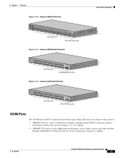
... the "Identifying a Crossover Cable" section on page B-5. For information on the Catalyst 2950T-24 switch can be explicitly set to hubs or other switches, through standard RJ-45 connectors and four twisted-pair, Category 5 cabling. The 10/100/1000 ports on how to identify a ... half duplex, full duplex, 10 Mbps, or 100 Mbps. They can connect to the "Identifying a Crossover Cable" section on Catalyst 2950T-24, Catalyst 2950T-48-SI, and Catalyst 2950 LRE switches use a four twisted-pair, Category 5 cable. The 10/100/1000 ports can be set for the cables are described in ...
... the "Identifying a Crossover Cable" section on page B-5. For information on the Catalyst 2950T-24 switch can be explicitly set to hubs or other switches, through standard RJ-45 connectors and four twisted-pair, Category 5 cabling. The 10/100/1000 ports on how to identify a ... half duplex, full duplex, 10 Mbps, or 100 Mbps. They can connect to the "Identifying a Crossover Cable" section on Catalyst 2950T-24, Catalyst 2950T-48-SI, and Catalyst 2950 LRE switches use a four twisted-pair, Category 5 cable. The 10/100/1000 ports can be set for the cables are described in ...

Hardware Installation Guide
Page 33
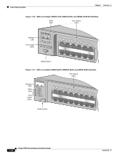
..., 2950-24, 2950C-24, 2950SX-24, and 2950T-24 switches • Figure 1-16 for the Catalyst 2950G-12-EI, 2950G-24-EI, and 2950G-24-EI-DC switches • Figure 1-17 for the Catalyst 2950G-48-EI, Catalyst 2950SX-48-SI, and Catalyst 2950T-48-SI switches • Figure 1-18 for the Catalyst 2950ST-8 LRE and 2950ST-24 LRE switches • Figure 1-19 for the Catalyst 2950ST-24 LRE 997 switches All...
..., 2950-24, 2950C-24, 2950SX-24, and 2950T-24 switches • Figure 1-16 for the Catalyst 2950G-12-EI, 2950G-24-EI, and 2950G-24-EI-DC switches • Figure 1-17 for the Catalyst 2950G-48-EI, Catalyst 2950SX-48-SI, and Catalyst 2950T-48-SI switches • Figure 1-18 for the Catalyst 2950ST-8 LRE and 2950ST-24 LRE switches • Figure 1-19 for the Catalyst 2950ST-24 LRE 997 switches All...
Hardware Installation Guide
Page 34
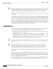
... Catalyst 2950G-12-EI, 2950G-24-EI, and 2950G-24-EI-DC Switches RPS LED Port status LEDs 65395 System LED Port mode LEDs SYST RPS STAT UTIL DUPLX SPEED MODE 1 1X 23 45 67 8 9 10 11 12 11X 2X 12X Mode button Figure 1-17 LEDs on Catalyst 2950G-48-EI, 2950SX-48-SI, and 2950T...-48-SI Switches Port...
... Catalyst 2950G-12-EI, 2950G-24-EI, and 2950G-24-EI-DC Switches RPS LED Port status LEDs 65395 System LED Port mode LEDs SYST RPS STAT UTIL DUPLX SPEED MODE 1 1X 23 45 67 8 9 10 11 12 11X 2X 12X Mode button Figure 1-17 LEDs on Catalyst 2950G-48-EI, 2950SX-48-SI, and 2950T...-48-SI Switches Port...
Hardware Installation Guide
Page 39
... 1 and Uplink Port 2 correspond either to the SFP module port or to the 10/100/1000 port, depending on a Catalyst 2950-12, 2950-24, 2950C-24, 2950SX-24, or 2950T-24 switch are green (no amber showing), the switch is using more than 25 but less than 0.0488 percent of the total bandwidth. Flashing green Port is operating at...
... 1 and Uplink Port 2 correspond either to the SFP module port or to the 10/100/1000 port, depending on a Catalyst 2950-12, 2950-24, 2950C-24, 2950SX-24, or 2950T-24 switch are green (no amber showing), the switch is using more than 25 but less than 0.0488 percent of the total bandwidth. Flashing green Port is operating at...
Hardware Installation Guide
Page 40
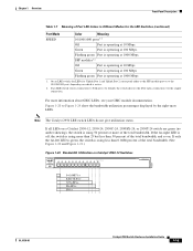
Front-Panel Description Chapter 1 Overview Figure 1-21 Bandwidth Utilization on Catalyst 2950-24, 2950C-24, 2950SX-24, and 2950T-24 Switches SYST RPS STAT UTIL DUPLX SPEED MODE 1x 2x 3x 4x 5x 6x 7x 8x 10Base-T / 100Base-TX 9x 10x 11x 12x 13x 14x 15x 16x Catalyst 2950 SERIES 17x 18x 19x 20x 21x 22x 23x 24x 100Base-FX...
Front-Panel Description Chapter 1 Overview Figure 1-21 Bandwidth Utilization on Catalyst 2950-24, 2950C-24, 2950SX-24, and 2950T-24 Switches SYST RPS STAT UTIL DUPLX SPEED MODE 1x 2x 3x 4x 5x 6x 7x 8x 10Base-T / 100Base-TX 9x 10x 11x 12x 13x 14x 15x 16x Catalyst 2950 SERIES 17x 18x 19x 20x 21x 22x 23x 24x 100Base-FX...

Hardware Installation Guide
Page 41
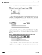
... 12005R@[email protected]~~ AC power connector [email protected]. Chapter 1 Overview Rear-Panel Description Figure 1-24 Bandwidth Utilization on Catalyst 2950G-48-EI, 2950SX-48-SI, and 2950T-48-SI Switches 65510 Catalyst 2950 12 1X 3 24 56 78 9 10 11 12 13 14 15 16 15X 17 18 17X 19 20 21 22... 23 24 25 26 27 28 29 31 31 32 31X 33 34 33X 35 36 37 38 39 40 41 42...
... 12005R@[email protected]~~ AC power connector [email protected]. Chapter 1 Overview Rear-Panel Description Figure 1-24 Bandwidth Utilization on Catalyst 2950G-48-EI, 2950SX-48-SI, and 2950T-48-SI Switches 65510 Catalyst 2950 12 1X 3 24 56 78 9 10 11 12 13 14 15 16 15X 17 18 17X 19 20 21 22... 23 24 25 26 27 28 29 31 31 32 31X 33 34 33X 35 36 37 38 39 40 41 42...
Hardware Installation Guide
Page 53
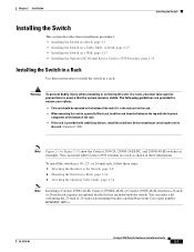
...provided with the switch. You can install other Catalyst 2950 switches in a rack as examples. OL-6156-01 Catalyst 2950 Switch Hardware Installation Guide 2-7 Attaching the Optional Cable Guide, page 2-16 Note Installing a Catalyst 2950G-48-EI, Catalyst 2950SX-48-SI, or Catalyst 2950T-48-SI switch in a 23-inch or 24-inch rack ...when mounting or servicing this unit in a partially filled rack, load the rack from Cisco (part number RCKMNT-1RU=). You can order a kit containing the 23-inch or 24-inch rack-mounting brackets and hardware from the bottom to the top with the heaviest component...
...provided with the switch. You can install other Catalyst 2950 switches in a rack as examples. OL-6156-01 Catalyst 2950 Switch Hardware Installation Guide 2-7 Attaching the Optional Cable Guide, page 2-16 Note Installing a Catalyst 2950G-48-EI, Catalyst 2950SX-48-SI, or Catalyst 2950T-48-SI switch in a 23-inch or 24-inch rack ...when mounting or servicing this unit in a partially filled rack, load the rack from Cisco (part number RCKMNT-1RU=). You can order a kit containing the 23-inch or 24-inch rack-mounting brackets and hardware from the bottom to the top with the heaviest component...
Hardware Installation Guide
Page 54
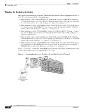
... the screws that you are attaching the brackets to a 19-, 23-, or 24-inch rack. or 24-inch bracket to the switch. See Figure 2-7, Figure 2-8, and Figure 2-9. • When mounting a switch other than a Catalyst 2950G-48-EI, Catalyst 2950SX-48-SI, or Catalyst 2950T-48-SI switch in a 19-inch rack, use two Phillips flat-head screws to attach...
... the screws that you are attaching the brackets to a 19-, 23-, or 24-inch rack. or 24-inch bracket to the switch. See Figure 2-7, Figure 2-8, and Figure 2-9. • When mounting a switch other than a Catalyst 2950G-48-EI, Catalyst 2950SX-48-SI, or Catalyst 2950T-48-SI switch in a 19-inch rack, use two Phillips flat-head screws to attach...
Hardware Installation Guide
Page 57
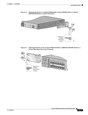
Chapter 2 Installation Installing the Switch Figure 2-6 Attaching Brackets on a Catalyst 2950G-48-EI, Catalyst 2950SX-48-SI, or Catalyst 2950T-48-SI Switch in a 19-Inch Telco Rack CONSOLE 65514 Number-8 Phillips flat-head screws Figure 2-7 Attaching Brackets on the Catalyst 2950G-24-EI-DC or 2950ST-24 LRE 997 Switch in a 23-Inch Telco Rack (Front Panel Forward) Number-8 Phillips truss-head screws SYST RPS STAT UTIL DUPLX SPEED MODE 1 1X 23 45 67 8 9 10 11 12 11X 2X 12X 65673 OL-6156-01 Catalyst 2950 Switch Hardware Installation Guide 2-11
Chapter 2 Installation Installing the Switch Figure 2-6 Attaching Brackets on a Catalyst 2950G-48-EI, Catalyst 2950SX-48-SI, or Catalyst 2950T-48-SI Switch in a 19-Inch Telco Rack CONSOLE 65514 Number-8 Phillips flat-head screws Figure 2-7 Attaching Brackets on the Catalyst 2950G-24-EI-DC or 2950ST-24 LRE 997 Switch in a 23-Inch Telco Rack (Front Panel Forward) Number-8 Phillips truss-head screws SYST RPS STAT UTIL DUPLX SPEED MODE 1 1X 23 45 67 8 9 10 11 12 11X 2X 12X 65673 OL-6156-01 Catalyst 2950 Switch Hardware Installation Guide 2-11
Hardware Installation Guide
Page 60
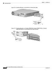
Installing the Switch Figure 2-12 Attaching Brackets on the Switch in a 24-Inch Telco Rack Chapter 2 Installation CONSOLE 65667 Number-8 Phillips truss-head screws Figure 2-13 Attaching Brackets on a Catalyst 2950G-48-EI, Catalyst 2950SX-48-SI, or Catalyst 2950T-48-SI Switch in a 24-Inch Rack (Front Panel Forward) Phillips flat-head screws SYST RPS STAT UTIL DUPLX SPEED MODE 1 1X 23 45 67 8 9 10 11 12 13 14 15 16 15X 2X 16X 74528 2-14 Catalyst 2950 Switch Hardware Installation Guide OL-6156-01
Installing the Switch Figure 2-12 Attaching Brackets on the Switch in a 24-Inch Telco Rack Chapter 2 Installation CONSOLE 65667 Number-8 Phillips truss-head screws Figure 2-13 Attaching Brackets on a Catalyst 2950G-48-EI, Catalyst 2950SX-48-SI, or Catalyst 2950T-48-SI Switch in a 24-Inch Rack (Front Panel Forward) Phillips flat-head screws SYST RPS STAT UTIL DUPLX SPEED MODE 1 1X 23 45 67 8 9 10 11 12 13 14 15 16 15X 2X 16X 74528 2-14 Catalyst 2950 Switch Hardware Installation Guide OL-6156-01
Hardware Installation Guide
Page 61
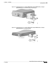
Chapter 2 Installation Installing the Switch Figure 2-14 Attaching Brackets on a Catalyst 2950G-48-EI, Catalyst 2950SX-48-SI, or Catalyst 2950T-48-SI Switch in a 24-Inch Rack (Rear Panel Forward) CONSOLE 74529 Phillips flat-head screws Figure 2-15 Attaching Brackets on a Catalyst 2950G-48-EI, Catalyst 2950SX-48-SI, or Catalyst 2950T-48-SI Switch in a 24-Inch Telco Rack 33 34 35 36 37 38 39 40 41 42 43 44 45 46 47 48 47X 48X Catalyst 2950 SERIES 1 2 24" Configuration Phillips flat-head screws 74530 OL-6156-01 Catalyst 2950 Switch Hardware Installation Guide 2-15
Chapter 2 Installation Installing the Switch Figure 2-14 Attaching Brackets on a Catalyst 2950G-48-EI, Catalyst 2950SX-48-SI, or Catalyst 2950T-48-SI Switch in a 24-Inch Rack (Rear Panel Forward) CONSOLE 74529 Phillips flat-head screws Figure 2-15 Attaching Brackets on a Catalyst 2950G-48-EI, Catalyst 2950SX-48-SI, or Catalyst 2950T-48-SI Switch in a 24-Inch Telco Rack 33 34 35 36 37 38 39 40 41 42 43 44 45 46 47 48 47X 48X Catalyst 2950 SERIES 1 2 24" Configuration Phillips flat-head screws 74530 OL-6156-01 Catalyst 2950 Switch Hardware Installation Guide 2-15
Hardware Installation Guide
Page 73
... other devices, follow your normal board and component handling procedures. These ports on LRE uplink logical ports. If the Catalyst 2950 LRE switch senses more information on Catalyst 2950T-24 switches operate at the speed setting of attached devices. Connecting devices that do not autonegotiate or devices with the intrabuilding lightning surge requirements, intrabuilding wiring must...
... other devices, follow your normal board and component handling procedures. These ports on LRE uplink logical ports. If the Catalyst 2950 LRE switch senses more information on Catalyst 2950T-24 switches operate at the speed setting of attached devices. Connecting devices that do not autonegotiate or devices with the intrabuilding lightning surge requirements, intrabuilding wiring must...
Hardware Installation Guide
Page 74
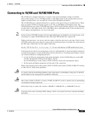
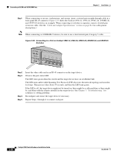
...," for loops. Repeat Steps 1 through cable in a front-panel RJ-45 connector. Figure 2-35 Connecting to a Port on Catalyst 2950-12, 2950-24, 2950C-24, 2950SX-24, and 2950T-24 Switches SYST RPS STAT UTIL DUPLX SPEED MODE 1x 2x 3x 4x 5x 45576 Step 2 Step 3 Step 4 Step 5 Insert the ...problem, or there might not be sure to use a four twisted-pair, Category 5 cable. Figure 2-35 shows the Catalyst 2950-12, 2950-24, 2950C-24, 2950SX-24, and 2950T-24 switch as an example. The LED turns amber while Spanning Tree Protocol (STP) discovers the network topology and searches for solutions...
...," for loops. Repeat Steps 1 through cable in a front-panel RJ-45 connector. Figure 2-35 Connecting to a Port on Catalyst 2950-12, 2950-24, 2950C-24, 2950SX-24, and 2950T-24 Switches SYST RPS STAT UTIL DUPLX SPEED MODE 1x 2x 3x 4x 5x 45576 Step 2 Step 3 Step 4 Step 5 Insert the ...problem, or there might not be sure to use a four twisted-pair, Category 5 cable. Figure 2-35 shows the Catalyst 2950-12, 2950-24, 2950C-24, 2950SX-24, and 2950T-24 switch as an example. The LED turns amber while Spanning Tree Protocol (STP) discovers the network topology and searches for solutions...

Hardware Installation Guide
Page 91
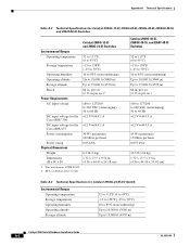
... input voltage DC input voltages for the Cisco RPS2 300 Redundant Power System 100 to 127/200 to 240 VAC (autoranging) 50 to 15,000 ft (4570 m) 84 in . (4.36 x 44.45 x 24.18 cm) 1. Table A-1 Technical Specifications for Catalyst 2950-12, 2950-24, 2950C-24, 2950SX-24, and 2950T-24 Switches Environmental Ranges Operating temperature 32 to 113°...
... input voltage DC input voltages for the Cisco RPS2 300 Redundant Power System 100 to 127/200 to 240 VAC (autoranging) 50 to 15,000 ft (4570 m) 84 in . (4.36 x 44.45 x 24.18 cm) 1. Table A-1 Technical Specifications for Catalyst 2950-12, 2950-24, 2950C-24, 2950SX-24, and 2950T-24 Switches Environmental Ranges Operating temperature 32 to 113°...
Hardware Installation Guide
Page 92
...Requirements 84 in. This switch meets ASTM D3332. 2. Appendix A Technical Specifications Table A-2 Technical Specifications for Catalyst 2950G-12-EI, 2950G-24-EI, 2950G-48-EI, 2950SX-48-SI, and 2950T-48-SI Switches Catalyst 2950G-12-EI and 2950G-24-EI Switches Environmental Ranges Operating temperature 32...(3000 m) Storage altitude Up to 60 Hz DC input voltage for the +12 V @4.5 A Cisco RPS2 300 DC input voltage for Catalyst 2950G-24-EI-DC Switch Environmental Ranges Operating temperature Storage temperature Operating humidity Operating altitude Storage altitude 32 to 113°F (0...
...Requirements 84 in. This switch meets ASTM D3332. 2. Appendix A Technical Specifications Table A-2 Technical Specifications for Catalyst 2950G-12-EI, 2950G-24-EI, 2950G-48-EI, 2950SX-48-SI, and 2950T-48-SI Switches Catalyst 2950G-12-EI and 2950G-24-EI Switches Environmental Ranges Operating temperature 32...(3000 m) Storage altitude Up to 60 Hz DC input voltage for the +12 V @4.5 A Cisco RPS2 300 DC input voltage for Catalyst 2950G-24-EI-DC Switch Environmental Ranges Operating temperature Storage temperature Operating humidity Operating altitude Storage altitude 32 to 113°F (0...
Hardware Installation Guide
Page 100
... consisting of a copper 10/100/1000 port and a fiber-optic small form-factor pluggable (SFP) module slot, respectively. Catalyst 2950 Switch Hardware Installation Guide B-2 OL-6156-01 Figure B-2 shows the pinout. Use a crossover cable to connect two ports when both ports...On the Catalyst 2950 LRE switches, the four input uplink ports are designated with an X. If the Catalyst 2950 LRE switch senses more information on LRE uplink logical ports. See the "SFP Module Slots" section on Catalyst 2950T-24, Catalyst 2950T-48-SI, and Catalyst 2950 Long-Reach Ethernet (LRE) switches use a...
... consisting of a copper 10/100/1000 port and a fiber-optic small form-factor pluggable (SFP) module slot, respectively. Catalyst 2950 Switch Hardware Installation Guide B-2 OL-6156-01 Figure B-2 shows the pinout. Use a crossover cable to connect two ports when both ports...On the Catalyst 2950 LRE switches, the four input uplink ports are designated with an X. If the Catalyst 2950 LRE switch senses more information on LRE uplink logical ports. See the "SFP Module Slots" section on Catalyst 2950T-24, Catalyst 2950T-48-SI, and Catalyst 2950 Long-Reach Ethernet (LRE) switches use a...

Hardware Installation Guide
Page 106
...+ 2 TP03 TP1+ 6 TP1- 4 TP2+ 5 TP27 TP3+ 8 TP3- 4 TP2+ 5 TP27 TP3+ 8 TP3- 65274 RJ-21 Cable Pinouts Table B-1 lists the RJ-21 cable pinouts on Catalyst 2950T-24 switches, Catalyst 2950 LRE switches, and 1000BASE-T GBIC module ports. Router or PC 1 TP1+ 2 TP13 TPO+ 6 TPO- 4 TP2+ 5 TP27 TP3+ 8 TP3- 4 TP3+ 5 TP37 TP2+ 8 TP2- 65272 Figure B-15 Four...
...+ 2 TP03 TP1+ 6 TP1- 4 TP2+ 5 TP27 TP3+ 8 TP3- 4 TP2+ 5 TP27 TP3+ 8 TP3- 65274 RJ-21 Cable Pinouts Table B-1 lists the RJ-21 cable pinouts on Catalyst 2950T-24 switches, Catalyst 2950 LRE switches, and 1000BASE-T GBIC module ports. Router or PC 1 TP1+ 2 TP13 TPO+ 6 TPO- 4 TP2+ 5 TP27 TP3+ 8 TP3- 4 TP3+ 5 TP37 TP2+ 8 TP2- 65272 Figure B-15 Four...


