
imageCLASS MF3111 Basic Guide
Page 65
...; On Windows XP: ❑ Click [Start] on the Windows task bar ➞ select [Control Panel] ➞ [Printers and Other Hardware] ➞ [Scanners and Cameras]. ● On Windows 98/Me/2000: ❑ Click [Start] on the Windows task bar ➞ select [Settings] ➞ [Control Panel]... ➞ double click [Scanners and Cameras]. 2 Make sure there is installed in the CD-ROM. Before Scanning 6-1 Before Scanning Before scanning, software must be installed in your computer...
...; On Windows XP: ❑ Click [Start] on the Windows task bar ➞ select [Control Panel] ➞ [Printers and Other Hardware] ➞ [Scanners and Cameras]. ● On Windows 98/Me/2000: ❑ Click [Start] on the Windows task bar ➞ select [Settings] ➞ [Control Panel]... ➞ double click [Scanners and Cameras]. 2 Make sure there is installed in the CD-ROM. Before Scanning 6-1 Before Scanning Before scanning, software must be installed in your computer...

imageCLASS MF3110 Basic Guide
Page 67
.... • If not, please see "Install the software and connect the machine to scan documents into your computer using the scanner driver included in the Software Guide. Before Scanning 6-1 Scanning 6 CHAPTER This chapter briefly explains how to your computer by following this procedure...● On Windows XP: ❑ Click [start] on the Windows task bar ➞ select [Control Panel] ➞ [Printers and Other Hardware] ➞ [Scanners and Cameras]. ● On Windows 98/Me/2000: ❑ Click [Start] on the Windows task bar ➞ select [Settings] ➞ [Control Panel] ...
.... • If not, please see "Install the software and connect the machine to scan documents into your computer using the scanner driver included in the Software Guide. Before Scanning 6-1 Scanning 6 CHAPTER This chapter briefly explains how to your computer by following this procedure...● On Windows XP: ❑ Click [start] on the Windows task bar ➞ select [Control Panel] ➞ [Printers and Other Hardware] ➞ [Scanners and Cameras]. ● On Windows 98/Me/2000: ❑ Click [Start] on the Windows task bar ➞ select [Settings] ➞ [Control Panel] ...
MF3110_spec.pdf
Page 1
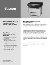
...with a USB 2.0 Hi-Speed interface.** An optional external print server is actually a copier, laser printer and color scanner all in one. Add the imageCLASS® MF3110 to 48-bit color depth at 1200 x 2400 dpi resolution* • 250-sheet front-loading cassette • USB...your workspace. The 250-sheet front-loading paper cassette and Single Cartridge System create effortless replenishing for continuous output. imageCLASS® MF3110 Laser Multifunction Printer | Copier | Scanner Stylish Laser Multifunction for Your Workspace • Laser output at 1200 x 600 dpi print quality • ...
...with a USB 2.0 Hi-Speed interface.** An optional external print server is actually a copier, laser printer and color scanner all in one. Add the imageCLASS® MF3110 to 48-bit color depth at 1200 x 2400 dpi resolution* • 250-sheet front-loading cassette • USB...your workspace. The 250-sheet front-loading paper cassette and Single Cartridge System create effortless replenishing for continuous output. imageCLASS® MF3110 Laser Multifunction Printer | Copier | Scanner Stylish Laser Multifunction for Your Workspace • Laser output at 1200 x 600 dpi print quality • ...
MF3110_spec.pdf
Page 2
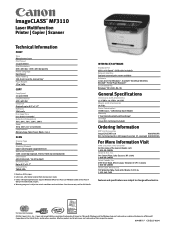
... Saver Mode) Warranty 1 Year limited warranty with exchange4 Cartridge Canon X25 Cartridge (included) Ordering Information MFP and Accessories imageCLASS MF3110 9866A001AA X25 Cartridge (yields 2,500 pages based on 5% coverage) 8489A001AA...MF3110 Laser Multifunction Printer | Copier | Scanner Technical Information PRINT Type Monochrome Laser Print Speed 21 ppm (letter) Print Resolution 600 x 600 dpi, 1200 x 600 dpi quality Printer Language Host-based Paper Feeding 250-sheet cassette, manual tray 1 Paper Weight 17 to change without notice. ©2004 Canon U.S.A., Inc., Canon and imageCLASS...
... Saver Mode) Warranty 1 Year limited warranty with exchange4 Cartridge Canon X25 Cartridge (included) Ordering Information MFP and Accessories imageCLASS MF3110 9866A001AA X25 Cartridge (yields 2,500 pages based on 5% coverage) 8489A001AA...MF3110 Laser Multifunction Printer | Copier | Scanner Technical Information PRINT Type Monochrome Laser Print Speed 21 ppm (letter) Print Resolution 600 x 600 dpi, 1200 x 600 dpi quality Printer Language Host-based Paper Feeding 250-sheet cassette, manual tray 1 Paper Weight 17 to change without notice. ©2004 Canon U.S.A., Inc., Canon and imageCLASS...

Service Manual
Page 8
... Supply PCB...3 12 3.1.11 Top Sensor...3 14 3.1.12 Paper Delivery Sensor ...3 17 3.2 Document Feed/Exposure System ...3 21 3.2.1 Scanner Unit ...3 21 3.2.2 Scanner Cover Unit ...3 22 3.2.3 CCD Unit...3 25 3.2.4 Flatbed Motor Unit...3 28 3.3 LASER EXPOSURE SYSTEM ...3 31 3.3.1 Laser/Scanner Unit ...3 31 3.4 IMAGE FORMATION SYSTEM...3 34 3.4.1 Transfer Charging Roller ...3 34 3.5 PICKUP AND FEEDING SYSTEM...3 35 3.5.1 Cassette...
... Supply PCB...3 12 3.1.11 Top Sensor...3 14 3.1.12 Paper Delivery Sensor ...3 17 3.2 Document Feed/Exposure System ...3 21 3.2.1 Scanner Unit ...3 21 3.2.2 Scanner Cover Unit ...3 22 3.2.3 CCD Unit...3 25 3.2.4 Flatbed Motor Unit...3 28 3.3 LASER EXPOSURE SYSTEM ...3 31 3.3.1 Laser/Scanner Unit ...3 31 3.4 IMAGE FORMATION SYSTEM...3 34 3.4.1 Transfer Charging Roller ...3 34 3.5 PICKUP AND FEEDING SYSTEM...3 35 3.5.1 Cassette...
Service Manual
Page 22
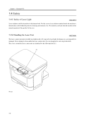
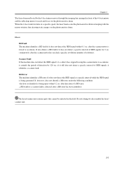
... light, the human eye can leaak from the machine in the field). The covers around the laser scanner unit are identified by the user. 1.4.2 Handling the Laser Unit 0007-8181 The laser scanner unit emits invisible laser light inside this machine is not designed for servicing in the normal operation of... 5 1.4 Safety 1.4.1 Safety of the product by the following label [1]. [1] F-1-4 1-8 Never attempt to the human body. No radiation can irreparably be hazardous to disassemble the laser scanner unit. (It is hermetically sealed within the protective housing and external cover.
... light, the human eye can leaak from the machine in the field). The covers around the laser scanner unit are identified by the user. 1.4.2 Handling the Laser Unit 0007-8181 The laser scanner unit emits invisible laser light inside this machine is not designed for servicing in the normal operation of... 5 1.4 Safety 1.4.1 Safety of the product by the following label [1]. [1] F-1-4 1-8 Never attempt to the human body. No radiation can irreparably be hazardous to disassemble the laser scanner unit. (It is hermetically sealed within the protective housing and external cover.
Service Manual
Page 30
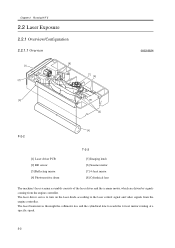
.... 2-2 Chapter 2ޓRunning H/F 5 2.2 Laser Exposure 2.2.1 Overview/Configuration 2.2.1.1 Overview [8] [1] [2] [7] [6] 0002-8624 [3] [5] [4] F-2-2 [1] Laser driver PCB [2] BD sensor [3] Reflecting mirror [4] Photosensitive drum T-2-2 [5] Imaging lends [6] Scanner motor [7] 4 facet mirror [8] Cylindrical lens The machine's laser scanner assembly consists of the laser driver and the scanner motor, which are driven by signals coming from the engine controller.
.... 2-2 Chapter 2ޓRunning H/F 5 2.2 Laser Exposure 2.2.1 Overview/Configuration 2.2.1.1 Overview [8] [1] [2] [7] [6] 0002-8624 [3] [5] [4] F-2-2 [1] Laser driver PCB [2] BD sensor [3] Reflecting mirror [4] Photosensitive drum T-2-2 [5] Imaging lends [6] Scanner motor [7] 4 facet mirror [8] Cylindrical lens The machine's laser scanner assembly consists of the laser driver and the scanner motor, which are driven by signals coming from the engine controller.
Service Manual
Page 31
...under the following condition: the door is being open within 0.1 sec after it has stopped forcing the scanner motor to reach and focus on the photosensitive drum. The laser/scanner unit contains parts that cannot be adjusted in front of detection by the 4 facet mirror moves through... signals for 2 sec continuously after a BD error has been identified. Do not attempt to accelerate. a BD fault or a scanner fault is forced to disassemble the laser/ scanner unit. 2-3 When the 4 facet mirror rotates at a specific interval while the /BDI signal is identified as being generated. if...
...under the following condition: the door is being open within 0.1 sec after it has stopped forcing the scanner motor to reach and focus on the photosensitive drum. The laser/scanner unit contains parts that cannot be adjusted in front of detection by the 4 facet mirror moves through... signals for 2 sec continuously after a BD error has been identified. Do not attempt to accelerate. a BD fault or a scanner fault is forced to disassemble the laser/ scanner unit. 2-3 When the 4 facet mirror rotates at a specific interval while the /BDI signal is identified as being generated. if...
Service Manual
Page 32
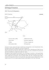
... to prepare for the formation of the toner from the developing cylinder. Chapter 2ޓRunning H/F 5 2.3 Image Formation 2.3.1 Overview/Configuration 2.3.1.1 Overview [2] [1] [8] [7] 0002-8626 [6] F-2-3 [3] [4] [5] [1] Laser/scanner assembly [2] Laser beam [3] Blade [4] Developing cylinder T-2-3 [5] Photosensitive drum [6] Transfer charging roller [7] Primary charging roller [8] Cleaning blade In response to a print command, the engine controller turns...
... to prepare for the formation of the toner from the developing cylinder. Chapter 2ޓRunning H/F 5 2.3 Image Formation 2.3.1 Overview/Configuration 2.3.1.1 Overview [2] [1] [8] [7] 0002-8626 [6] F-2-3 [3] [4] [5] [1] Laser/scanner assembly [2] Laser beam [3] Blade [4] Developing cylinder T-2-3 [5] Photosensitive drum [6] Transfer charging roller [7] Primary charging roller [8] Cleaning blade In response to a print command, the engine controller turns...

Service Manual
Page 35
... identical to stop the rotation of the feed roller so that the paper will not move forward until the laser/scanner and the fixing unit become ready for operation. When the laser/scanner and the fixing unit become ready for operation, the machine turns off before a specific period of time passes. Wrap...
... identical to stop the rotation of the feed roller so that the paper will not move forward until the laser/scanner and the fixing unit become ready for operation. When the laser/scanner and the fixing unit become ready for operation, the machine turns off before a specific period of time passes. Wrap...

Service Manual
Page 39
the CPU causes the relay drive signal to go Low to cut off the power to turn off the main motor, scanner motor, and high voltage system and puts the printer unit in the fixing assembly for 0.3 sec continuously while fixing heater temperature control is under way, ...
the CPU causes the relay drive signal to go Low to cut off the power to turn off the main motor, scanner motor, and high voltage system and puts the printer unit in the fixing assembly for 0.3 sec continuously while fixing heater temperature control is under way, ...

Service Manual
Page 43
...Cassette ...3 2 3.1.3.2 Removing the right cover ...3 2 3.1.3.3 Removing the left cover ...3 3 3.1.3.4 Removing the rear cover ...3 3 3.1.3.5 Removing the Scanner Unit...3 3 3.1.3.6 Removing the Top Cover ...3 4 3.1.4 Right Cover ...3 4 3.1.4.1 Removing the Cassette ...3 4 3.1.4.2 Removing the right cover ...3 ...3.1.6.2 Removing the right cover ...3 5 3.1.6.3 Removing the left cover ...3 6 3.1.6.4 Removing the rear cover ...3 6 3.1.6.5 Removing the Scanner Unit...3 6 3.1.6.6 Removing the Board Unit...3 7 3.1.6.7 Removing the Operation Panel Unit...3 7 3.1.7 SCNT Board...3 7 3.1.7.1 Removing the ...
...Cassette ...3 2 3.1.3.2 Removing the right cover ...3 2 3.1.3.3 Removing the left cover ...3 3 3.1.3.4 Removing the rear cover ...3 3 3.1.3.5 Removing the Scanner Unit...3 3 3.1.3.6 Removing the Top Cover ...3 4 3.1.4 Right Cover ...3 4 3.1.4.1 Removing the Cassette ...3 4 3.1.4.2 Removing the right cover ...3 ...3.1.6.2 Removing the right cover ...3 5 3.1.6.3 Removing the left cover ...3 6 3.1.6.4 Removing the rear cover ...3 6 3.1.6.5 Removing the Scanner Unit...3 6 3.1.6.6 Removing the Board Unit...3 7 3.1.6.7 Removing the Operation Panel Unit...3 7 3.1.7 SCNT Board...3 7 3.1.7.1 Removing the ...

Service Manual
Page 44
......3 16 3.1.11.3 Removing the left cover...3 16 3.1.11.4 Removing the front cover ...3 17 3.1.11.5 Removing the rear cover...3 17 3.1.11.6 Removing the Scanner Unit...3 17 3.1.11.7 Removing the Top Cover...3 18 3.1.11.8 Removing the Right Frame...3 18 3.1.11.9 Removing the Plate...3 18 3.1.11.10 Removing the ... the front cover ...3 21 3.1.12.5 Removing the rear cover...3 21 3.1.12.6 Removing the Power Supply Shield Plate 3 21 3.1.12.7 Removing the Scanner Unit...3 21 3.1.12.8 Removing the Plate...3 22 3.1.12.9 Removing the Paper Delivery Sensor 3 22 3.2 Document Feed/Exposure System ...3 23...
......3 16 3.1.11.3 Removing the left cover...3 16 3.1.11.4 Removing the front cover ...3 17 3.1.11.5 Removing the rear cover...3 17 3.1.11.6 Removing the Scanner Unit...3 17 3.1.11.7 Removing the Top Cover...3 18 3.1.11.8 Removing the Right Frame...3 18 3.1.11.9 Removing the Plate...3 18 3.1.11.10 Removing the ... the front cover ...3 21 3.1.12.5 Removing the rear cover...3 21 3.1.12.6 Removing the Power Supply Shield Plate 3 21 3.1.12.7 Removing the Scanner Unit...3 21 3.1.12.8 Removing the Plate...3 22 3.1.12.9 Removing the Paper Delivery Sensor 3 22 3.2 Document Feed/Exposure System ...3 23...
Service Manual
Page 45
...left cover ...3 27 3.2.3.4 Removing the rear cover ...3 28 3.2.3.5 Removing the Scanner Unit...3 28 3.2.3.6 Removing the Board Unit...3 28 3.2.3.7 Removing the Operation Panel Unit 3 29 3.2.3.8 Removing the Scanner Cover Unit...3 29 3.2.3.9 Removing the Flatbed Motor Unit ...3 29 3.2.3.10 ...34 3.3.1.3 Removing the left cover ...3 34 3.3.1.4 Removing the rear cover ...3 35 3.3.1.5 Removing the Scanner Unit...3 35 3.3.1.6 Removing the Top Cover ...3 35 3.3.1.7 Removing the Laser/Scanner Unit...3 36 3.4 IMAGE FORMATION SYSTEM ...3 37 3.4.1 Transfer Charging Roller ...3 37 3.4.1.1 Removing the ...
...left cover ...3 27 3.2.3.4 Removing the rear cover ...3 28 3.2.3.5 Removing the Scanner Unit...3 28 3.2.3.6 Removing the Board Unit...3 28 3.2.3.7 Removing the Operation Panel Unit 3 29 3.2.3.8 Removing the Scanner Cover Unit...3 29 3.2.3.9 Removing the Flatbed Motor Unit ...3 29 3.2.3.10 ...34 3.3.1.3 Removing the left cover ...3 34 3.3.1.4 Removing the rear cover ...3 35 3.3.1.5 Removing the Scanner Unit...3 35 3.3.1.6 Removing the Top Cover ...3 35 3.3.1.7 Removing the Laser/Scanner Unit...3 36 3.4 IMAGE FORMATION SYSTEM ...3 37 3.4.1 Transfer Charging Roller ...3 37 3.4.1.1 Removing the ...

Service Manual
Page 46
......3 42 3.5.2.3 Removing the left cover...3 43 3.5.2.4 Removing the front cover ...3 43 3.5.2.5 Removing the rear cover...3 43 3.5.2.6 Removing the Scanner Unit...3 44 3.5.2.7 Removing the Top Cover...3 44 3.5.2.8 Removing the Right Frame...3 44 3.5.2.9 Removing the Plate...3 45 3.5.2.10 Removing the ... 47 3.5.4.3 Removing the left cover...3 47 3.5.4.4 Removing the front cover ...3 48 3.5.4.5 Removing the rear cover...3 48 3.5.4.6 Removing the Scanner Unit...3 48 3.5.4.7 Removing the Top Cover...3 49 3.5.4.8 Removing the Right Frame...3 49 3.5.4.9 Removing the Plate...3 49 3.5.4.10 Removing the ...
......3 42 3.5.2.3 Removing the left cover...3 43 3.5.2.4 Removing the front cover ...3 43 3.5.2.5 Removing the rear cover...3 43 3.5.2.6 Removing the Scanner Unit...3 44 3.5.2.7 Removing the Top Cover...3 44 3.5.2.8 Removing the Right Frame...3 44 3.5.2.9 Removing the Plate...3 45 3.5.2.10 Removing the ... 47 3.5.4.3 Removing the left cover...3 47 3.5.4.4 Removing the front cover ...3 48 3.5.4.5 Removing the rear cover...3 48 3.5.4.6 Removing the Scanner Unit...3 48 3.5.4.7 Removing the Top Cover...3 49 3.5.4.8 Removing the Right Frame...3 49 3.5.4.9 Removing the Plate...3 49 3.5.4.10 Removing the ...

Service Manual
Page 47
... 56 3.5.6.3 Removing the left cover ...3 56 3.5.6.4 Removing the front cover...3 57 3.5.6.5 Removing the rear cover ...3 57 3.5.6.6 Removing the Scanner Unit...3 57 3.5.6.7 Removing the Top Cover ...3 58 3.5.6.8 Removing the Right Frame ...3 58 3.5.6.9 Removing the Plate...3 58 3.5.6.10 Removing the... 61 3.6.1.3 Removing the left cover ...3 61 3.6.1.4 Removing the front cover...3 62 3.6.1.5 Removing the rear cover ...3 62 3.6.1.6 Removing the Scanner Unit...3 62 3.6.1.7 Removing the Top Cover ...3 63 3.6.1.8 Removing the Right Frame ...3 63 3.6.1.9 Removing the Plate...3 63 3.6.1.10 Removing the...
... 56 3.5.6.3 Removing the left cover ...3 56 3.5.6.4 Removing the front cover...3 57 3.5.6.5 Removing the rear cover ...3 57 3.5.6.6 Removing the Scanner Unit...3 57 3.5.6.7 Removing the Top Cover ...3 58 3.5.6.8 Removing the Right Frame ...3 58 3.5.6.9 Removing the Plate...3 58 3.5.6.10 Removing the... 61 3.6.1.3 Removing the left cover ...3 61 3.6.1.4 Removing the front cover...3 62 3.6.1.5 Removing the rear cover ...3 62 3.6.1.6 Removing the Scanner Unit...3 62 3.6.1.7 Removing the Top Cover ...3 63 3.6.1.8 Removing the Right Frame ...3 63 3.6.1.9 Removing the Plate...3 63 3.6.1.10 Removing the...

Service Manual
Page 51
... front cover [1], and remove the 2 screws [2] on the front side. [2] [1] F-3-9 2) Remove the 2 screws [1] on the back side, and remove the left cover [2]. [2] [3] [3] [1] [4] F-3-11 3.1.3.5 Removing the Scanner Unit 0007-7460 1) Remove the connector [1] and the flat cable [2] on the ECNT board, and remove the screw [3]. (Remove the flat cable from the core...
... front cover [1], and remove the 2 screws [2] on the front side. [2] [1] F-3-9 2) Remove the 2 screws [1] on the back side, and remove the left cover [2]. [2] [3] [3] [1] [4] F-3-11 3.1.3.5 Removing the Scanner Unit 0007-7460 1) Remove the connector [1] and the flat cable [2] on the ECNT board, and remove the screw [3]. (Remove the flat cable from the core...

Service Manual
Page 52
Chapter 3ޓ 3) Remove the 2 screws on the front side. Slide the scanner unit [2] to the back; F-3-16 3.1.5 Left Cover 3.1.5.1 Removing the Cassette 0002-6874 1) Remove the cassette by holding the cassette handle. then, remove it by holding ...
Chapter 3ޓ 3) Remove the 2 screws on the front side. Slide the scanner unit [2] to the back; F-3-16 3.1.5 Left Cover 3.1.5.1 Removing the Cassette 0002-6874 1) Remove the cassette by holding the cassette handle. then, remove it by holding ...

Service Manual
Page 54
... pressure release levers [2] on both sides and release the pressure. 2) Remove 2 screws [3]. 3) Remove the rear cover [4] as you pull it toward you. [2] [3] [3] [1] [4] F-3-23 3.1.6.5 Removing the Scanner Unit 0007-7489 1) Remove the connector [1] and the flat cable [2] on the ECNT board, and remove the screw [3]. (Remove the flat cable from the core...
... pressure release levers [2] on both sides and release the pressure. 2) Remove 2 screws [3]. 3) Remove the rear cover [4] as you pull it toward you. [2] [3] [3] [1] [4] F-3-23 3.1.6.5 Removing the Scanner Unit 0007-7489 1) Remove the connector [1] and the flat cable [2] on the ECNT board, and remove the screw [3]. (Remove the flat cable from the core...

Service Manual
Page 55
3) Remove the 2 screws on the back side of the scanner unit. F-3-28 2) Remove the 2 claws [2] on the operation panel unit [1], and remove the operation panel unit. [2] [1] F-3-26 2) Open the board unit [1], and ...cables [4]. [4] [1] [2] [1] F-3-29 3.1.7 SCNT Board 3.1.7.1 Removing the Cassette 0006-2984 1) Remove the cassette by lifting it by holding the cassette handle. [3] F-3-27 3-7 Slide the scanner unit [2] to the back; then, remove it . [2] [1] Chapter 3 3.1.6.7 Removing Operation Panel Unit the 0007-7491 1) Reomve the 2 screws [1], and remove the flat cable from the...
3) Remove the 2 screws on the back side of the scanner unit. F-3-28 2) Remove the 2 claws [2] on the operation panel unit [1], and remove the operation panel unit. [2] [1] F-3-26 2) Open the board unit [1], and ...cables [4]. [4] [1] [2] [1] F-3-29 3.1.7 SCNT Board 3.1.7.1 Removing the Cassette 0006-2984 1) Remove the cassette by lifting it by holding the cassette handle. [3] F-3-27 3-7 Slide the scanner unit [2] to the back; then, remove it . [2] [1] Chapter 3 3.1.6.7 Removing Operation Panel Unit the 0007-7491 1) Reomve the 2 screws [1], and remove the flat cable from the...


