Service Manual
Page 4
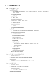
... Tools 1-5. Warnings 2-4. CONNECTOR LOCATION AND PIN LAYOUT 2-1. Customer Maintenance 1-3. Carriage Board (Print Head Connector) PIXMA iP4200 Specifications LIST OF ERROR DISPLAY / INDICATION 2-1. Troubleshooting by Service Engineer 1-2. Verification ... 3-2. NEW TECHNOLOGIES 2. Operator Call Errors 2-2. REPAIR 3-1. Notes on Repair Servicing 3-3. CLEANING MODE AND AMOUNT OF INK PURGED 3. Logic Board Ass'y 2-2. II. Product Life 1-4. Adjustment, Periodic Maintenance, Periodic Replacement Parts, and Replacement Consumables by Symptom 3. Adjustment / Settings ...
... Tools 1-5. Warnings 2-4. CONNECTOR LOCATION AND PIN LAYOUT 2-1. Customer Maintenance 1-3. Carriage Board (Print Head Connector) PIXMA iP4200 Specifications LIST OF ERROR DISPLAY / INDICATION 2-1. Troubleshooting by Service Engineer 1-2. Verification ... 3-2. NEW TECHNOLOGIES 2. Operator Call Errors 2-2. REPAIR 3-1. Notes on Repair Servicing 3-3. CLEANING MODE AND AMOUNT OF INK PURGED 3. Logic Board Ass'y 2-2. II. Product Life 1-4. Adjustment, Periodic Maintenance, Periodic Replacement Parts, and Replacement Consumables by Symptom 3. Adjustment / Settings ...
Service Manual
Page 6
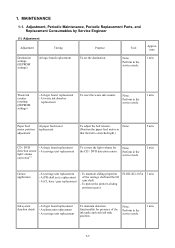
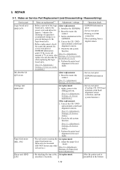
... carriage shaft and the lift cam shaft. - Grease application - To protect the printer's sliding portions (gears). At logic board replacement - None. Adjustment, Periodic Maintenance, Periodic Replacement Parts, and Replacement Consumables by Service Engineer (1) Adjustment Adjustment Timing Purpose... unit replacement To maintain detection functionality for the CD / DVD detection sensor. 1. time Destination settings (EEPROM settings) At logic board replacement To set the destination. Waste ink counter resetting (EEPROM settings) - At waste ink absorber replacement To reset the...
... carriage shaft and the lift cam shaft. - Grease application - To protect the printer's sliding portions (gears). At logic board replacement - None. Adjustment, Periodic Maintenance, Periodic Replacement Parts, and Replacement Consumables by Service Engineer (1) Adjustment Adjustment Timing Purpose... unit replacement To maintain detection functionality for the CD / DVD detection sensor. 1. time Destination settings (EEPROM settings) At logic board replacement To set the destination. Waste ink counter resetting (EEPROM settings) - At waste ink absorber replacement To reset the...

Service Manual
Page 12
... Cycles of blinking in an ink tank (the ink tank LED is turned off ). Platen unit (QM2-2202) - Timing sensor unit (QM2-2683) - Logic board ass'y (QM2-2670)*1 - Replace the ink tank(s). or longer to be re-done. 13 times 14 times 15 times The remaining ink amount unknown. [...to record the use of listed parts, which has once been empty is disabled. *1: Only for models supporting CD / DVD printing *2: Only for 5 sec. Logic board ass'y (QM2-2670)*1 - head alignment will not be faulty) - Replace the applicable ink tank with a once-empty or refilled ink tank can damage the...
... Cycles of blinking in an ink tank (the ink tank LED is turned off ). Platen unit (QM2-2202) - Timing sensor unit (QM2-2683) - Logic board ass'y (QM2-2670)*1 - Replace the ink tank(s). or longer to be re-done. 13 times 14 times 15 times The remaining ink amount unknown. [...to record the use of listed parts, which has once been empty is disabled. *1: Only for models supporting CD / DVD printing *2: Only for 5 sec. Logic board ass'y (QM2-2670)*1 - head alignment will not be faulty) - Replace the applicable ink tank with a once-empty or refilled ink tank can damage the...

Service Manual
Page 13
... [5700] - Logic board ass'y (QM2-2670)*1 EEPROM error [6800] - Logic board ass'y (QM2-2670)*1 - Logic board ass'y (QM2-2670)*1 14 times 15 times 16 times Paper feed cam sensor error - Logic board ass'y (QM2-2670)*1 - Logic board ass'y (QM2-2670)*1 20 times Other hardware error [6500] - Logic board ass'y (QM2-2670)*1 - Adjustment / Settings, (5) Service mode, for details.] 1-8 Logic board ass'y (QM2-2670)*1 - Logic board ass'y (QM2...
... [5700] - Logic board ass'y (QM2-2670)*1 EEPROM error [6800] - Logic board ass'y (QM2-2670)*1 - Logic board ass'y (QM2-2670)*1 14 times 15 times 16 times Paper feed cam sensor error - Logic board ass'y (QM2-2670)*1 - Logic board ass'y (QM2-2670)*1 20 times Other hardware error [6500] - Logic board ass'y (QM2-2670)*1 - Adjustment / Settings, (5) Service mode, for details.] 1-8 Logic board ass'y (QM2-2670)*1 - Logic board ass'y (QM2...
Service Manual
Page 14
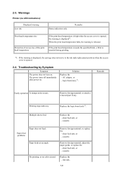
... is opened . 2-4. Remove foreign material, or replace the - Replace the - Troubleshooting by Symptom Symptom The power does not turn on . logic board ass'y*1. sheet feed unit, or - AC adapter, or - Replace the logic board ass'y*1. Paper feed problems Paper does not feed. Remarks Faulty operation A strange noise occurs. Printing stops mid-way. Replace the...
... is opened . 2-4. Remove foreign material, or replace the - Replace the - Troubleshooting by Symptom Symptom The power does not turn on . logic board ass'y*1. sheet feed unit, or - AC adapter, or - Replace the logic board ass'y*1. Paper feed problems Paper does not feed. Remarks Faulty operation A strange noise occurs. Printing stops mid-way. Replace the...
Service Manual
Page 15
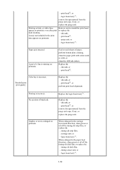
...head*2, or remove foreign material from the purge unit caps, if any , or replace the purge unit. timing sensor unit, or - logic board ass'y*1, remove foreign material from the purge unit caps, if any , or replace the purge unit. print head*2, - Unsatisfactory print ...sub-rollers. Remove and re-install the print head, or replace the - timing slit strip film, - Paper gets smeared. Replace the - logic board ass'y*1. 1-10 Graphic or text is missing on printouts. timing slit disk film, - When enlarged in the print data appears on printouts....
...head*2, or remove foreign material from the purge unit caps, if any , or replace the purge unit. timing sensor unit, or - logic board ass'y*1, remove foreign material from the purge unit caps, if any , or replace the purge unit. print head*2, - Unsatisfactory print ...sub-rollers. Remove and re-install the print head, or replace the - timing slit strip film, - Paper gets smeared. Replace the - logic board ass'y*1. 1-10 Graphic or text is missing on printouts. timing slit disk film, - When enlarged in the print data appears on printouts....
Service Manual
Page 16
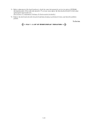
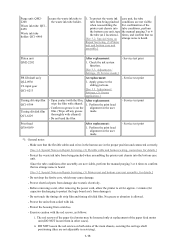
To the top 1-11 Adjustment / Settings, (5) Service mode, for details.] *2: Replace the print head only after the print head deep cleaning is 7% or more, also replace the ink absorber kit (QY5-0146) when replacing the logic board ass'y. [See Section 3-3. *1: Before replacement of the logic board ass'y, check the waste ink amount (by service test print or EEPROM information print). If the waste ink amount is performed 2 times, and when the problem persists.
To the top 1-11 Adjustment / Settings, (5) Service mode, for details.] *2: Replace the print head only after the print head deep cleaning is 7% or more, also replace the ink absorber kit (QY5-0146) when replacing the logic board ass'y. [See Section 3-3. *1: Before replacement of the logic board ass'y, check the waste ink amount (by service test print or EEPROM information print). If the waste ink amount is performed 2 times, and when the problem persists.
Service Manual
Page 17
... cord, and allow for approx. 1 minute (for details of capacitor's accumulated charges), to prevent damages to 5] when replacing the logic board ass'y. 6. Reset the waste ink counter. 3. Check the ink system EEPROM information function. Service test print - Perform the print head... the printer unit is 7% or more, also Settings, (5) Service mode, replace the ink absorber kit for discharge of 1 to the 1. logic board ass'y. 4. Apply grease to be loosened. The red screws securing the At replacement: paper feed motor are 1. Perform the print head alignment ...
... cord, and allow for approx. 1 minute (for details of capacitor's accumulated charges), to prevent damages to 5] when replacing the logic board ass'y. 6. Reset the waste ink counter. 3. Check the ink system EEPROM information function. Service test print - Perform the print head... the printer unit is 7% or more, also Settings, (5) Service mode, replace the ink absorber kit for discharge of 1 to the 1. logic board ass'y. 4. Apply grease to be loosened. The red screws securing the At replacement: paper feed motor are 1. Perform the print head alignment ...
Service Manual
Page 18
... power cord, allow the printer to sit for approx. 1 minute (for capacitor discharging to static electricity. - Protect electrical parts from damage due to protect the logic board ass'y from soiled with ethanol. 1. Before removing a unit, after assembly are in the user mode. - Do not touch the timing slit strip film and timing...
... power cord, allow the printer to sit for approx. 1 minute (for capacitor discharging to static electricity. - Protect electrical parts from damage due to protect the logic board ass'y from soiled with ethanol. 1. Before removing a unit, after assembly are in the user mode. - Do not touch the timing slit strip film and timing...
Service Manual
Page 21
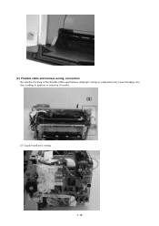
Improper wiring or connection may cause breakage of a line, leading to ignition or emission of the flexible cables and harness. (2) Flexible cable and harness wiring, connection Be careful of wiring of smoke. (I) Logic board ass'y wiring 1-16
Improper wiring or connection may cause breakage of a line, leading to ignition or emission of the flexible cables and harness. (2) Flexible cable and harness wiring, connection Be careful of wiring of smoke. (I) Logic board ass'y wiring 1-16
Service Manual
Page 27
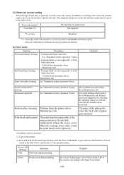
... / Settings, (5) Service mode, for ink tank replacement. (Open the access cover. Also available from the printer driver Maintenance tab. (3) Waste ink counter setting When the logic board ass'y is given in the table below. Waste ink amount*1 Less than 7% Ink absorber kit replacement Not required. 7% or more Required. *1: Check the waste ink...
... / Settings, (5) Service mode, for ink tank replacement. (Open the access cover. Also available from the printer driver Maintenance tab. (3) Waste ink counter setting When the logic board ass'y is given in the table below. Waste ink amount*1 Less than 7% Ink absorber kit replacement Not required. 7% or more Required. *1: Check the waste ink...
Service Manual
Page 49
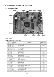
Logic Board Ass'y CN101 Not used CN201 (Print head 1/2 [Carriage unit]) No. OUT OUT OUT OUT OUT IN OUT OUT OUT OUT OUT... H_D8 18 H_ENB1 19 H_LATCH 20 H_EEPROM_CS Function AB power supply AB data signal AB power supply AB CLK signal Logic GND Head data (SC1) Head data (BK1) Head data (BK2) Head data (SM1) Head heat enable signal 0 (BK...) Logic GND Diode sensor anode 0 Logic GND Head data (C1) Head data (M1) Head heat enable signal 3 (SCol) Head data (Y1) Head heat enable signal 1 (Col-1) ...
Logic Board Ass'y CN101 Not used CN201 (Print head 1/2 [Carriage unit]) No. OUT OUT OUT OUT OUT IN OUT OUT OUT OUT OUT... H_D8 18 H_ENB1 19 H_LATCH 20 H_EEPROM_CS Function AB power supply AB data signal AB power supply AB CLK signal Logic GND Head data (SC1) Head data (BK1) Head data (BK2) Head data (SM1) Head heat enable signal 0 (BK...) Logic GND Diode sensor anode 0 Logic GND Head data (C1) Head data (M1) Head heat enable signal 3 (SCol) Head data (Y1) Head heat enable signal 1 (Col-1) ...
Service Manual
Page 54
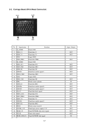
...OUT OUT OUT OUT OUT OUT OUT OUT OUT IN OUT OUT OUT OUT OUT OUT OUT OUT OUT IN OUT OUT OUT IN Carriage Board (Print Head Connector) No. 2-2. Signal name 1, 2 A_GNDH 3 HD2_C1 4 HD8_Y1 5 VSS 6 HD6_PBK1 7, 8 B_GNDH 9 HD3_SC1 10....3V 28 ROM_CS 29 HCLK 30 ROM_DIO (O) Function Head GND Head data C1 Head data Y1 Logic GND Head data PBK1 Head GND Head data SC1 Head data SM1 Head data M1 Head heat enable signal 1... Head data SM2 Logic GND Head data M2 Diode sensor cathode Head data BK1 Head heat enable signal 0 Head heat enable signal...
...OUT OUT OUT OUT OUT OUT OUT OUT OUT IN OUT OUT OUT OUT OUT OUT OUT OUT OUT IN OUT OUT OUT IN Carriage Board (Print Head Connector) No. 2-2. Signal name 1, 2 A_GNDH 3 HD2_C1 4 HD8_Y1 5 VSS 6 HD6_PBK1 7, 8 B_GNDH 9 HD3_SC1 10....3V 28 ROM_CS 29 HCLK 30 ROM_DIO (O) Function Head GND Head data C1 Head data Y1 Logic GND Head data PBK1 Head GND Head data SC1 Head data SM1 Head data M1 Head heat enable signal 1... Head data SM2 Logic GND Head data M2 Diode sensor cathode Head data BK1 Head heat enable signal 0 Head heat enable signal...


