Service Manual
Page 2
... TO CERTAIN AREAS. Prepared by OFFICE IMAGING PRODUCTS TECHNICAL SUPPORT DIVISION CANON INC. 5-1, Hakusan 7-chome, Toride-shi, Ibaraki 302-8501 Japan COPYRIGHT © 1999 CANON INC. CANON PC800s/900s REV.0 AUG. 1999 PRINTED IN JAPAN (IMPRIME AU JAPON) COPYRIGHT © 1999 CANON INC. SPECIFICATIONS AND OTHER INFORMATION CONTAINED HEREIN MAY VARY SLIGHTLY FROM ACTUAL MACHINE...
... TO CERTAIN AREAS. Prepared by OFFICE IMAGING PRODUCTS TECHNICAL SUPPORT DIVISION CANON INC. 5-1, Hakusan 7-chome, Toride-shi, Ibaraki 302-8501 Japan COPYRIGHT © 1999 CANON INC. CANON PC800s/900s REV.0 AUG. 1999 PRINTED IN JAPAN (IMPRIME AU JAPON) COPYRIGHT © 1999 CANON INC. SPECIFICATIONS AND OTHER INFORMATION CONTAINED HEREIN MAY VARY SLIGHTLY FROM ACTUAL MACHINE...
Service Manual
Page 3
... how they may be disassembled/assembled and adjusted. It also shows how the unit may be disassembled/assembled and adjusted. CANON PC800s/900s REV.0 AUG. 1999 PRINTED IN JAPAN (IMPRIME AU JAPON) i Appendix contains a general timing chart and general circuit diagrams...on a step-by -step instructions. This service manual consists of the following chapters: Chapter 1 General Description introduces the machine's features, specifications, names of operation used for the machine's image formation system. Chapter 6 Fixing System discusses the principles of operation used for the machine...
... how they may be disassembled/assembled and adjusted. It also shows how the unit may be disassembled/assembled and adjusted. CANON PC800s/900s REV.0 AUG. 1999 PRINTED IN JAPAN (IMPRIME AU JAPON) i Appendix contains a general timing chart and general circuit diagrams...on a step-by -step instructions. This service manual consists of the following chapters: Chapter 1 General Description introduces the machine's features, specifications, names of operation used for the machine's image formation system. Chapter 6 Fixing System discusses the principles of operation used for the machine...
Service Manual
Page 4
... of the DC controller PCB to the loads. The descriptions in this Service Manual: 1. Each chapter contains sections explaining the purpose of specific functions and the relationship between electrical and mechanical systems with power. 2. In the diagrams, represents the path of mechanical drive-where a ...signal name accompanies the symbol nal. , the arrow indicates the direction of operation. CANON PC800s/900s REV.0 AUG. 1999 PRINTED IN JAPAN (IMPRIME AU JAPON) ii COPYRIGHT © 1999 CANON INC. In the digital circuits, '1' is used to indicate that the voltage level of a ...
... of the DC controller PCB to the loads. The descriptions in this Service Manual: 1. Each chapter contains sections explaining the purpose of specific functions and the relationship between electrical and mechanical systems with power. 2. In the diagrams, represents the path of mechanical drive-where a ...signal name accompanies the symbol nal. , the arrow indicates the direction of operation. CANON PC800s/900s REV.0 AUG. 1999 PRINTED IN JAPAN (IMPRIME AU JAPON) ii COPYRIGHT © 1999 CANON INC. In the digital circuits, '1' is used to indicate that the voltage level of a ...
Service Manual
Page 7
FEATURES 1-1 II. Copier 1-2 B. External View 1-10 B. Functional Construction ........2-1 B. Exposure System 3-37 COPYRIGHT © 1999 CANON INC. CANON PC800s/900s REV.0 AUG. 1999 PRINTED IN JAPAN (IMPRIME AU JAPON) v ROUTINE MAINTENANCE BY THE USER 1-17 VI. Inputs to and Outputs from the ... Electrical Circuitry 2-2 C. OPERATIONS 3-1 A. Varying the Reproduction Ratio 3-2 C. Control Panel 1-15 V. CONTENTS CHAPTER 1 GENERAL DESCRIPTION I. BASIC OPERATIONS 2-1 A. IMAGE FORMATION 1-20 A. Controlling the Main Motor (M1 2-5 E. SPECIFICATIONS 1-2 A.
FEATURES 1-1 II. Copier 1-2 B. External View 1-10 B. Functional Construction ........2-1 B. Exposure System 3-37 COPYRIGHT © 1999 CANON INC. CANON PC800s/900s REV.0 AUG. 1999 PRINTED IN JAPAN (IMPRIME AU JAPON) v ROUTINE MAINTENANCE BY THE USER 1-17 VI. Inputs to and Outputs from the ... Electrical Circuitry 2-2 C. OPERATIONS 3-1 A. Varying the Reproduction Ratio 3-2 C. Control Panel 1-15 V. CONTENTS CHAPTER 1 GENERAL DESCRIPTION I. BASIC OPERATIONS 2-1 A. IMAGE FORMATION 1-20 A. Controlling the Main Motor (M1 2-5 E. SPECIFICATIONS 1-2 A.
Service Manual
Page 11
I. Copier 1-2 B. Outline 1-20 COPYRIGHT © 1999 CANON INC. ADF 1-8 III. Cross Section 1-13 IV. Control Panel 1-15 V. ROUTINE MAINTENANCE BY THE USER 1-17 VI. IMAGE FORMATION 1-20 A. CHAPTER 1 GENERAL DESCRIPTION This chapter provides specifications of the machine, instructions on how to operate the machine, and an outline of copying process. FEATURES 1-1 II. SPECIFICATIONS 1-2 A. USING THE MACHINE 1-15 A. NAMES OF PARTS 1-10 A. External View 1-10 B. CANON PC800s/900s REV.0 AUG. 1999 PRINTED IN JAPAN (IMPRIME AU JAPON)
I. Copier 1-2 B. Outline 1-20 COPYRIGHT © 1999 CANON INC. ADF 1-8 III. Cross Section 1-13 IV. Control Panel 1-15 V. ROUTINE MAINTENANCE BY THE USER 1-17 VI. IMAGE FORMATION 1-20 A. CHAPTER 1 GENERAL DESCRIPTION This chapter provides specifications of the machine, instructions on how to operate the machine, and an outline of copying process. FEATURES 1-1 II. SPECIFICATIONS 1-2 A. USING THE MACHINE 1-15 A. NAMES OF PARTS 1-10 A. External View 1-10 B. CANON PC800s/900s REV.0 AUG. 1999 PRINTED IN JAPAN (IMPRIME AU JAPON)
Service Manual
Page 14
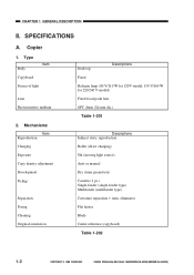
... charging) Slit (moving light source) Auto or manual Dry (toner projection) Cassette (1 pc.) Single-feeder (single-feeder type) Multifeeder (multifeeder type) Curvature separation + static eliminator Flat heater Blade Center reference (copyboard) Table 1-202 1-2 COPYRIGHT © 1999 CANON INC. SPECIFICATIONS A. Copier 1. CANON PC800s/900s REV.0 AUG. 1999 PRINTED IN JAPAN (IMPRIME AU JAPON) CHAPTER 1 GENERAL...
... charging) Slit (moving light source) Auto or manual Dry (toner projection) Cassette (1 pc.) Single-feeder (single-feeder type) Multifeeder (multifeeder type) Curvature separation + static eliminator Flat heater Blade Center reference (copyboard) Table 1-202 1-2 COPYRIGHT © 1999 CANON INC. SPECIFICATIONS A. Copier 1. CANON PC800s/900s REV.0 AUG. 1999 PRINTED IN JAPAN (IMPRIME AU JAPON) CHAPTER 1 GENERAL...
Service Manual
Page 19
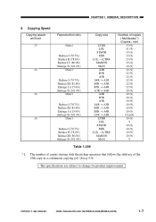
...LGL → LTRR MARJIN MAX Number of the 19th copy in a continuous copying job. (See p.5-8) The specifications are subject to change for product improvement. CHAPTER 1 GENERAL DESCRIPTION 6. COPYRIGHT © 1999 CANON INC. The number of copies starting with the pickup operation that follows the delivery of copies ( Multifeeder*1) (... 13 (9) 10 (9) 12 (9) 12 (9) 12 (9) 12 (9) 12 (9) 12 (9) 10 (9) 10 (9) 10 (9) 10 (9) 10 (9) 10 (9) 10 (9) 10 m(9) 10 (9) 9 10 (9) 10 (9) 10 (9) 10 (9) 9 Table 1-206 *1. CANON PC800s/900s REV.0 AUG. 1999 PRINTED IN JAPAN (IMPRIME AU JAPON) 1-7
...LGL → LTRR MARJIN MAX Number of the 19th copy in a continuous copying job. (See p.5-8) The specifications are subject to change for product improvement. CHAPTER 1 GENERAL DESCRIPTION 6. COPYRIGHT © 1999 CANON INC. The number of copies starting with the pickup operation that follows the delivery of copies ( Multifeeder*1) (... 13 (9) 10 (9) 12 (9) 12 (9) 12 (9) 12 (9) 12 (9) 12 (9) 10 (9) 10 (9) 10 (9) 10 (9) 10 (9) 10 (9) 10 (9) 10 m(9) 10 (9) 9 10 (9) 10 (9) 10 (9) 10 (9) 9 Table 1-206 *1. CANON PC800s/900s REV.0 AUG. 1999 PRINTED IN JAPAN (IMPRIME AU JAPON) 1-7
Service Manual
Page 21
COPYRIGHT © 1999 CANON INC. CANON PC800s/900s REV.0 AUG. 1999 PRINTED IN JAPAN (IMPRIME AU JAPON) 1-9 The following may not be used as an original: • Sheet with a staple, clip, or glue. • Sheet with a cut, hole, or tear. • Sheet with curling, bending, or wrinkling. The specifications are subject to change for binding. • Sheet with a carbon back. • Sheet with a cut-and-paste piece. • Sheet with holes for product improvement. CHAPTER 1 GENERAL DESCRIPTION *1.
COPYRIGHT © 1999 CANON INC. CANON PC800s/900s REV.0 AUG. 1999 PRINTED IN JAPAN (IMPRIME AU JAPON) 1-9 The following may not be used as an original: • Sheet with a staple, clip, or glue. • Sheet with a cut, hole, or tear. • Sheet with curling, bending, or wrinkling. The specifications are subject to change for binding. • Sheet with a carbon back. • Sheet with a cut-and-paste piece. • Sheet with holes for product improvement. CHAPTER 1 GENERAL DESCRIPTION *1.
Service Manual
Page 42
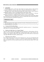
...motor is a DC motor with a built-in clock pulse generator, which generates clock pulses (MMCLK) in the display. 2-6 COPYRIGHT © 1999 CANON INC. CANON PC800s/900s REV.0 AUG. 1999 PRINTED IN JAPAN (IMPRIME AU JAPON) Rotating the Main Motor at a Constant Speed The drive circuit on the ... the frequency of the clock pulse signals (MMCLK) occurring when the motor rotates and that of the frequency of the main motor deviates from a specific number for some reason, the MLOCK signal goes '1'. If the signal remains '1' for about 1 sec, the DC controller will find the condition ...
...motor is a DC motor with a built-in clock pulse generator, which generates clock pulses (MMCLK) in the display. 2-6 COPYRIGHT © 1999 CANON INC. CANON PC800s/900s REV.0 AUG. 1999 PRINTED IN JAPAN (IMPRIME AU JAPON) Rotating the Main Motor at a Constant Speed The drive circuit on the ... the frequency of the clock pulse signals (MMCLK) occurring when the motor rotates and that of the frequency of the main motor deviates from a specific number for some reason, the MLOCK signal goes '1'. If the signal remains '1' for about 1 sec, the DC controller will find the condition ...
Service Manual
Page 61
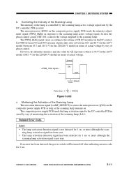
... after indicating an error code for 1 sec or more although the scan- COPYRIGHT © 1999 CANON INC. CANON PC800s/900s REV.0 AUG. 1999 PRINTED IN JAPAN (IMPRIME AU JAPON) 3-11 CHAPTER 3 EXPOSURE SYSTEM b. However, the intensity remains a specific value for the 220/240 V model) in response to the scanning lamp active voltage signal...
... after indicating an error code for 1 sec or more although the scan- COPYRIGHT © 1999 CANON INC. CANON PC800s/900s REV.0 AUG. 1999 PRINTED IN JAPAN (IMPRIME AU JAPON) 3-11 CHAPTER 3 EXPOSURE SYSTEM b. However, the intensity remains a specific value for the 220/240 V model) in response to the scanning lamp active voltage signal...

Service Manual
Page 98
... roller, and has the following functions: • Turning on and off the DC/AC bias • Controlling the DC bias to a specific voltage • Controlling the AC bias to a specific voltage • Switching the level of the photosensitive drum will be uniform. Outline The circuit shown in Figure 4-103 is switched between... DC bias Both DC bias and AC bias are applied to the primary charging roller so as to 3000 Vpp (885µA) 4-4 COPYRIGHT © 1999 CANON INC. CANON PC800s/900s REV.0 AUG. 1999 PRINTED IN JAPAN (IMPRIME AU JAPON) CHAPTER 4 IMAGE FORMATION SYSTEM C.
... roller, and has the following functions: • Turning on and off the DC/AC bias • Controlling the DC bias to a specific voltage • Controlling the AC bias to a specific voltage • Switching the level of the photosensitive drum will be uniform. Outline The circuit shown in Figure 4-103 is switched between... DC bias Both DC bias and AC bias are applied to the primary charging roller so as to 3000 Vpp (885µA) 4-4 COPYRIGHT © 1999 CANON INC. CANON PC800s/900s REV.0 AUG. 1999 PRINTED IN JAPAN (IMPRIME AU JAPON) CHAPTER 4 IMAGE FORMATION SYSTEM C.
Service Manual
Page 100
...composite power supply PCB generates the DC bias control signal (PDC_PWM) based on the combination of the DC/AC bias. 4-6 COPYRIGHT © 1999 CANON INC. cation signal from the DC controller PCB, the microprocessor (Q900) on the composite power supply PCB generates the AC bias output signal (...the serial communi- When the Copy Start key is generated, the microprocessor (Q900) on the composite power supply PCB so that they remain a specific level. When the AC bias ON signal arrives from the DC controller PCB. Operations a. Reference: The DC bias control signal varies its pulse...
...composite power supply PCB generates the DC bias control signal (PDC_PWM) based on the combination of the DC/AC bias. 4-6 COPYRIGHT © 1999 CANON INC. cation signal from the DC controller PCB, the microprocessor (Q900) on the composite power supply PCB generates the AC bias output signal (...the serial communi- When the Copy Start key is generated, the microprocessor (Q900) on the composite power supply PCB so that they remain a specific level. When the AC bias ON signal arrives from the DC controller PCB. Operations a. Reference: The DC bias control signal varies its pulse...
Service Manual
Page 103
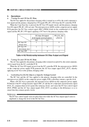
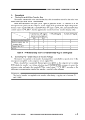
COPYRIGHT © 1999 CANON INC. Operations a. CANON PC800s/900s REV.0 AUG. 1999 PRINTED IN JAPAN (IMPRIME AU JAPON) 4-9 Turning On and Off the Transfer Bias The transfer bias applied to the ...ATVC Transfer bias ON signal (serial communication) bit2 bit3 1 0 1 1 0 0 0 1 T-FW_ON signal 1 1 0 1 T_REV_ON* signal 1 0 1 1 Table 4-103 Relationship between -7.5 and -3.0 kV. When a transfer bias is controlled to a specific level by the microprocessor (Q900) on and off by the DC controller PCB, the microprocessor (Q900) on the composite power supply PCB checks the transfer...
COPYRIGHT © 1999 CANON INC. Operations a. CANON PC800s/900s REV.0 AUG. 1999 PRINTED IN JAPAN (IMPRIME AU JAPON) 4-9 Turning On and Off the Transfer Bias The transfer bias applied to the ...ATVC Transfer bias ON signal (serial communication) bit2 bit3 1 0 1 1 0 0 0 1 T-FW_ON signal 1 1 0 1 T_REV_ON* signal 1 0 1 1 Table 4-103 Relationship between -7.5 and -3.0 kV. When a transfer bias is controlled to a specific level by the microprocessor (Q900) on and off by the DC controller PCB, the microprocessor (Q900) on the composite power supply PCB checks the transfer...
Service Manual
Page 104
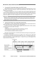
...Q900) checks the transfer current detection signal four times, and determines the level of the transfer bias to apply using the average of a specific level (-14.6 µA) is executed The polarity of the transfer bias (constant current control, + 1.56µA/2.5 kV max.) will ...) Transfer bias 1.2sec (approx.) 0.8sec (approx.) 0.7sec (approx.) 1.6sec(approx.) Figure 4-106 4-10 COPYRIGHT © 1999 CANON INC. A current of the readings. CANON PC800s/900s REV.0 AUG. 1999 PRINTED IN JAPAN (IMPRIME AU JAPON) CHAPTER 4 IMAGE FORMATION SYSTEM c. In response to the signal,...
...Q900) checks the transfer current detection signal four times, and determines the level of the transfer bias to apply using the average of a specific level (-14.6 µA) is executed The polarity of the transfer bias (constant current control, + 1.56µA/2.5 kV max.) will ...) Transfer bias 1.2sec (approx.) 0.8sec (approx.) 0.7sec (approx.) 1.6sec(approx.) Figure 4-106 4-10 COPYRIGHT © 1999 CANON INC. A current of the readings. CANON PC800s/900s REV.0 AUG. 1999 PRINTED IN JAPAN (IMPRIME AU JAPON) CHAPTER 4 IMAGE FORMATION SYSTEM c. In response to the signal,...

Service Manual
Page 107
... DC bias control signal (BIAS_PWM), thereby applying a DC bias to the static eliminator (static eliminator bias, about 3.2 kV). COPYRIGHT © 1999 CANON INC. CHAPTER 4 IMAGE FORMATION SYSTEM 2. When the developing DCON signal (serial signal) and the developing DC bias ON sign (DV_DC_ON) are generated ... gener- The DC controller PCB sends the developing AC bias ON signal (DV_AC_ON) to the developing cylinder. posite power supply PCB a specific period of time after copy paper has moved past the registration sensor. Turning On and Off the AC Bias The AC bias is applied...
... DC bias control signal (BIAS_PWM), thereby applying a DC bias to the static eliminator (static eliminator bias, about 3.2 kV). COPYRIGHT © 1999 CANON INC. CHAPTER 4 IMAGE FORMATION SYSTEM 2. When the developing DCON signal (serial signal) and the developing DC bias ON sign (DV_DC_ON) are generated ... gener- The DC controller PCB sends the developing AC bias ON signal (DV_AC_ON) to the developing cylinder. posite power supply PCB a specific period of time after copy paper has moved past the registration sensor. Turning On and Off the AC Bias The AC bias is applied...
Service Manual
Page 129
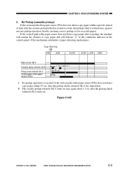
...once again to rotate, the pickup roller is executed if the vertical path roller paper sensor (PS4) does not detect copy paper within a specific period of time after the cassette pickup roller has started to execute pickup operation, thereby ensuring correct pickup (as for recycled paper). CHAPTER 5... PICK-UP/FEEDING SYSTEM 3. Figure 5-105 COPYRIGHT © 1999 CANON INC. II : The cassette pickup solenoid (SL5) turns on once again about 1.3 sec after the pickup clutch solenoid (SL1) has turned don...
...once again to rotate, the pickup roller is executed if the vertical path roller paper sensor (PS4) does not detect copy paper within a specific period of time after the cassette pickup roller has started to execute pickup operation, thereby ensuring correct pickup (as for recycled paper). CHAPTER 5... PICK-UP/FEEDING SYSTEM 3. Figure 5-105 COPYRIGHT © 1999 CANON INC. II : The cassette pickup solenoid (SL5) turns on once again about 1.3 sec after the pickup clutch solenoid (SL1) has turned don...

Service Manual
Page 133
... the registration clutch solenoid at a specific timing in response to the photosensitive drum. The microprocessor on the DC controller PCB turns on , the claw will reach the registration roller to move the copy paper to the paper detection signal from the pre-registration roller paper sensor. CANON PC800s/900s REV.0 AUG. 1999... clutch solenoid drive signal (RGSLD*) DC controller PCB Pre-registration roller paper detection signal (RPD) Figure 5-109 Preregistration roller paper sensor (Q751) COPYRIGHT © 1999 CANON INC. CHAPTER 5 PICK-UP/FEEDING SYSTEM C.
... the registration clutch solenoid at a specific timing in response to the photosensitive drum. The microprocessor on the DC controller PCB turns on , the claw will reach the registration roller to move the copy paper to the paper detection signal from the pre-registration roller paper sensor. CANON PC800s/900s REV.0 AUG. 1999... clutch solenoid drive signal (RGSLD*) DC controller PCB Pre-registration roller paper detection signal (RPD) Figure 5-109 Preregistration roller paper sensor (Q751) COPYRIGHT © 1999 CANON INC. CHAPTER 5 PICK-UP/FEEDING SYSTEM C.
Service Manual
Page 136
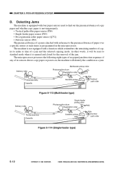
... Photosensitive drum PS5 Registration roller Q751 Cassette pickup roller PS4 Vertical path roller Figure 5-114 (Single-feeder type) 5-12 COPYRIGHT © 1999 CANON INC. in other words, it is not equipped with reference to make at time of its sensors detects copy paper at such times as ... presence/absence of a jam is checked with a function which remembers the remaining number of copies to the presence/absence of paper over a specific sensor at power-on, the machine will be reset to standard mode when it will identify the condition as programmed in the microprocessor. if ...
... Photosensitive drum PS5 Registration roller Q751 Cassette pickup roller PS4 Vertical path roller Figure 5-114 (Single-feeder type) 5-12 COPYRIGHT © 1999 CANON INC. in other words, it is not equipped with reference to make at time of its sensors detects copy paper at such times as ... presence/absence of a jam is checked with a function which remembers the remaining number of copies to the presence/absence of paper over a specific sensor at power-on, the machine will be reset to standard mode when it will identify the condition as programmed in the microprocessor. if ...

Service Manual
Page 137
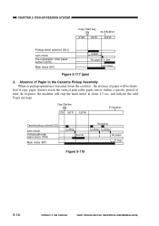
...5sec Figure 5-116 (no paper, pickup delay jam) If copy paper does not reach the pre-registration roller paper sensor within a specific period of paper; CANON PC800s/900s REV.0 AUG. 1999 PRINTED IN JAPAN (IMPRIME AU JAPON) 5-13 If the pre-registration roller paper sensor detects copy paper..., the condition will be identified as a pickup delay jam, and flash the Jam indicator. Multifeeder Pickup Assembly (no paper) COPYRIGHT © 1999 CANON INC. the machine will identify the condition as the absence of time in about 1.5 sec, and indicate the Add Paper message. CHAPTER 5 PICK...
...5sec Figure 5-116 (no paper, pickup delay jam) If copy paper does not reach the pre-registration roller paper sensor within a specific period of paper; CANON PC800s/900s REV.0 AUG. 1999 PRINTED IN JAPAN (IMPRIME AU JAPON) 5-13 If the pre-registration roller paper sensor detects copy paper..., the condition will be identified as a pickup delay jam, and flash the Jam indicator. Multifeeder Pickup Assembly (no paper) COPYRIGHT © 1999 CANON INC. the machine will identify the condition as the absence of time in about 1.5 sec, and indicate the Add Paper message. CHAPTER 5 PICK...
Service Manual
Page 138
... the machine will be identi- CANON PC800s/900s REV.0 AUG. 1999 PRINTED IN JAPAN (IMPRIME AU JAPON) Absence of Paper in about 1.5 sec, and indicate the Add Paper message. fied if copy paper doesnot reach the vertical path roller paper sensor within a specific period of paper will stop the ... paper sensor (PS4) Main motor (M1) 1.2sec Normal Re-pickup 1.2sec 1.2sec No paper 1.5sec Figure 5-118 5-14 COPYRIGHT © 1999 CANON INC. CHAPTER 5 PICK-UP/FEEDING SYSTEM Copy Start key ON STBY INTR indication SCFW Pickup clutch solenoid (SL1) Jam check Pre-registration roller paper sensor...
... the machine will be identi- CANON PC800s/900s REV.0 AUG. 1999 PRINTED IN JAPAN (IMPRIME AU JAPON) Absence of Paper in about 1.5 sec, and indicate the Add Paper message. fied if copy paper doesnot reach the vertical path roller paper sensor within a specific period of paper will stop the ... paper sensor (PS4) Main motor (M1) 1.2sec Normal Re-pickup 1.2sec 1.2sec No paper 1.5sec Figure 5-118 5-14 COPYRIGHT © 1999 CANON INC. CHAPTER 5 PICK-UP/FEEDING SYSTEM Copy Start key ON STBY INTR indication SCFW Pickup clutch solenoid (SL1) Jam check Pre-registration roller paper sensor...
