Service Manual
Page 10
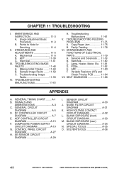
...M. Mechanical 11-5 B. Troubleshooting Image Faults 11-53 IV. AE SENSOR CIRCUIT DIAGRAM A-29 I . HIGH VOLTAGE CONTACT CIRCUIT DIAGRAM A-32 L. CANON PC800s/900s REV.0 AUG. 1999 PRINTED IN JAPAN (IMPRIME AU JAPON) Points to Note for Servicing 11-4 II. STANDARDS AND ADJUSTMENTS 11-5...11-81 D. BLANK EXPOSURE (rear) CIRCUIT DIAGRAM A-34 N. ADF CONTROLLER CIRCUIT DIAGRAM A-15 F. ADF 11-30 C. GENERAL TIMING CHART ........ NOISE FILTER CIRCUIT DIAGRAM A-31 K. ADF 11-83 F. Electrical 11-41 III. Faulty Feeding 11-78 VI. Variable Resistors (VR) and Check Pins...
...M. Mechanical 11-5 B. Troubleshooting Image Faults 11-53 IV. AE SENSOR CIRCUIT DIAGRAM A-29 I . HIGH VOLTAGE CONTACT CIRCUIT DIAGRAM A-32 L. CANON PC800s/900s REV.0 AUG. 1999 PRINTED IN JAPAN (IMPRIME AU JAPON) Points to Note for Servicing 11-4 II. STANDARDS AND ADJUSTMENTS 11-5...11-81 D. BLANK EXPOSURE (rear) CIRCUIT DIAGRAM A-34 N. ADF CONTROLLER CIRCUIT DIAGRAM A-15 F. ADF 11-30 C. GENERAL TIMING CHART ........ NOISE FILTER CIRCUIT DIAGRAM A-31 K. ADF 11-83 F. Electrical 11-41 III. Faulty Feeding 11-78 VI. Variable Resistors (VR) and Check Pins...

Service Manual
Page 17
...to 1013.25 hPa (0.6 to 1 atm) 120 V 60 Hz 220/240 V 50 Hz, 60 Hz Serial number Maximum power consumption Noise Ozone TVBxxxxx TVCxxxxx TVDxxxxx TVExxxxx TVFxxxxx TVGxxxxx TVHxxxxx TVJxxxxx PUDxxxxx PUExxxxx PUFxxxxx PUGxxxxx TYAxxxxx TZAxxxxx UAAxxxxx PUHxxxxx 0.9 kW or less Standby: 1.2W (...only) Copying: 0.4kWh (approx.; CHAPTER 1 GENERAL DESCRIPTION 4. Toner: Avoid direct sunlight, and store at 40°C/104°F, 85% or less. CANON PC800s/900s REV.0 AUG. 1999 PRINTED IN JAPAN (IMPRIME AU JAPON) 1-5 reference only) Standby: -(sound power level by ISO) Copying: (sound ...
...to 1013.25 hPa (0.6 to 1 atm) 120 V 60 Hz 220/240 V 50 Hz, 60 Hz Serial number Maximum power consumption Noise Ozone TVBxxxxx TVCxxxxx TVDxxxxx TVExxxxx TVFxxxxx TVGxxxxx TVHxxxxx TVJxxxxx PUDxxxxx PUExxxxx PUFxxxxx PUGxxxxx TYAxxxxx TZAxxxxx UAAxxxxx PUHxxxxx 0.9 kW or less Standby: 1.2W (...only) Copying: 0.4kWh (approx.; CHAPTER 1 GENERAL DESCRIPTION 4. Toner: Avoid direct sunlight, and store at 40°C/104°F, 85% or less. CANON PC800s/900s REV.0 AUG. 1999 PRINTED IN JAPAN (IMPRIME AU JAPON) 1-5 reference only) Standby: -(sound power level by ISO) Copying: (sound ...
Service Manual
Page 45
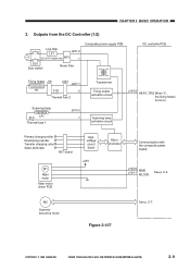
... MLOCK See p. 2-5. Outputs from the DC Controller (1/2) Line filter LF1 J201-2 (220/240V model only) NF1 -1 DS1 Door switch Noise filter Composite power supply PCB DC controller PCB Fixing heater J16 J434 J207-1 H1 FU2 -2 Thermal fuse 2 Scanning lamp FU1 LA1 Thermal ... Transformer Fixing heater activation circuit Scanning lamp activation circuit J104-2 HEAT_TRG When '0', the fixing heater turns on. COPYRIGHT © 1999 CANON INC. CANON PC800s/900s REV.0 AUG. 1999 PRINTED IN JAPAN (IMPRIME AU JAPON) 2-9 M2 Scanner/ lens drive motor Figure 2-107 See p. 3-7. CHAPTER...
... MLOCK See p. 2-5. Outputs from the DC Controller (1/2) Line filter LF1 J201-2 (220/240V model only) NF1 -1 DS1 Door switch Noise filter Composite power supply PCB DC controller PCB Fixing heater J16 J434 J207-1 H1 FU2 -2 Thermal fuse 2 Scanning lamp FU1 LA1 Thermal ... Transformer Fixing heater activation circuit Scanning lamp activation circuit J104-2 HEAT_TRG When '0', the fixing heater turns on. COPYRIGHT © 1999 CANON INC. CANON PC800s/900s REV.0 AUG. 1999 PRINTED IN JAPAN (IMPRIME AU JAPON) 2-9 M2 Scanner/ lens drive motor Figure 2-107 See p. 3-7. CHAPTER...

Service Manual
Page 183
Outline of the Power Supply System Door switch DS1 Power plug Noise filter circuit Relay RL601 FU102 Main transformer T101 Composite power supply circuit Transformer T600 Auxiliary power supply circuit +5V Microprocessor (Q900) DC power supply ...Main motor/ main motor M1 driver PCB Fixing heater Scanning lamp Primary charging roller Developing roller Transfer roller Static eliminator Figure 7-201 COPYRIGHT © 1999 CANON INC. POWER SUPPLY SYSTEM A. CANON PC800s/900s REV.0 AUG. 1999 PRINTED IN JAPAN (IMPRIME AU JAPON) 7-3 CHAPTER 7 EXTERNALS/AUXILIARY MECHANISMS II.
Outline of the Power Supply System Door switch DS1 Power plug Noise filter circuit Relay RL601 FU102 Main transformer T101 Composite power supply circuit Transformer T600 Auxiliary power supply circuit +5V Microprocessor (Q900) DC power supply ...Main motor/ main motor M1 driver PCB Fixing heater Scanning lamp Primary charging roller Developing roller Transfer roller Static eliminator Figure 7-201 COPYRIGHT © 1999 CANON INC. POWER SUPPLY SYSTEM A. CANON PC800s/900s REV.0 AUG. 1999 PRINTED IN JAPAN (IMPRIME AU JAPON) 7-3 CHAPTER 7 EXTERNALS/AUXILIARY MECHANISMS II.

Service Manual
Page 250
... made correctly. 24 Clean the externals of the machine and the area around the machine. 9-8 COPYRIGHT © 1999 CANON INC. CANON PC800s/900s REV.0 AUG. 1999 PRINTED IN JAPAN (IMPRIME AU JAPON) mal noise. CHAPTER 9 INSTALLATION Step Work 20 Attach the copy tray. and make copies to make sure that come with the...
... made correctly. 24 Clean the externals of the machine and the area around the machine. 9-8 COPYRIGHT © 1999 CANON INC. CANON PC800s/900s REV.0 AUG. 1999 PRINTED IN JAPAN (IMPRIME AU JAPON) mal noise. CHAPTER 9 INSTALLATION Step Work 20 Attach the copy tray. and make copies to make sure that come with the...
Service Manual
Page 323
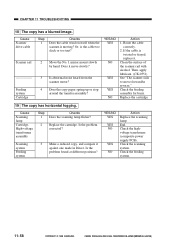
...11 TROUBLESHOOTING 18 The copy has a blurred image. Route the cable correctly. 2. Check the feeding assembly for burrs. Is abnormal noise heard from the scanner motor? YES/NO YES NO YES YES NO Action 1. Replace the cartridge. 19 The copy has horizontal ... up or stop around the transfer assembly? Check the highvoltage transformer (composite power supply PCB). Check the feeding system. 11-58 COPYRIGHT © 1999 CANON INC. Move the No. 1 mirror mount slowly by hand. Is the problem corrected? Cause Scanner drive cable Scanner rail Feeding system Cartridge Step 1 ...
...11 TROUBLESHOOTING 18 The copy has a blurred image. Route the cable correctly. 2. Check the feeding assembly for burrs. Is abnormal noise heard from the scanner motor? YES/NO YES NO YES YES NO Action 1. Replace the cartridge. 19 The copy has horizontal ... up or stop around the transfer assembly? Check the highvoltage transformer (composite power supply PCB). Check the feeding system. 11-58 COPYRIGHT © 1999 CANON INC. Move the No. 1 mirror mount slowly by hand. Is the problem corrected? Cause Scanner drive cable Scanner rail Feeding system Cartridge Step 1 ...

Service Manual
Page 332
...V, 5 A 220/240V model: 250 V, 2.5 A Remove the door switch (DS1), and connect the meter probes to turn on the composite power supply PCB; CANON PC800s/900s REV.0 AUG. 1999 PRINTED IN JAPAN (IMPRIME AU JAPON) 11-67 Is the machine's top unit closed firmly? Is the rated voltage present... NO YES NO NO YES Action Connect the power plug. Cause Power plug Machine top unit Power supply Fuse (FU501) Fuse (FU102) Door switch (DS1) Noise filter PCB Harness Connector connection 1 Connector connection 2 Control panel PCB Composite power supply PCB Step 1 2 3 4 5 6 7 8 9 10 11 12 Checks Is ...
...V, 5 A 220/240V model: 250 V, 2.5 A Remove the door switch (DS1), and connect the meter probes to turn on the composite power supply PCB; CANON PC800s/900s REV.0 AUG. 1999 PRINTED IN JAPAN (IMPRIME AU JAPON) 11-67 Is the machine's top unit closed firmly? Is the rated voltage present... NO YES NO NO YES Action Connect the power plug. Cause Power plug Machine top unit Power supply Fuse (FU501) Fuse (FU102) Door switch (DS1) Noise filter PCB Harness Connector connection 1 Connector connection 2 Control panel PCB Composite power supply PCB Step 1 2 3 4 5 6 7 8 9 10 11 12 Checks Is ...
Service Manual
Page 347
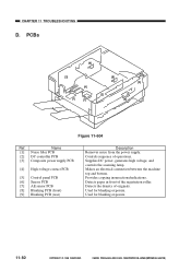
...contact PCB [5] Control panel PCB [6] Sensor PCB [7] AE sensor PCB [8] Blanking PCB (front) [9] Blanking PCB (rear) Description Removes noise from the power supply. Makes an electrical connection between the machine top and bottom. Used for blanking exposure. 11-82 COPYRIGHT © 1999... CANON INC. Provides copying insurrections/indications. Detects the density of the registration roller. CANON PC800s/900s REV.0 AUG. 1999 PRINTED IN JAPAN (IMPRIME AU JAPON) CHAPTER 11 TROUBLESHOOTING D. ...
...contact PCB [5] Control panel PCB [6] Sensor PCB [7] AE sensor PCB [8] Blanking PCB (front) [9] Blanking PCB (rear) Description Removes noise from the power supply. Makes an electrical connection between the machine top and bottom. Used for blanking exposure. 11-82 COPYRIGHT © 1999... CANON INC. Provides copying insurrections/indications. Detects the density of the registration roller. CANON PC800s/900s REV.0 AUG. 1999 PRINTED IN JAPAN (IMPRIME AU JAPON) CHAPTER 11 TROUBLESHOOTING D. ...
Service Manual
Page 360
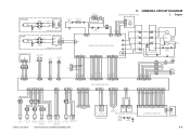
... M1 M BP701 BP705 PR +24VU GND MMD MLOCK [120V] H N FT2 FT4 FT1 FT3 J1 DS1 Door switch JP502 JP501 J501 2 1 J501F 2 1 NF1 NOISE FILTER PCB 2 1 J201 123 J910 21 J207 4321 J205 J209 J212 COMPOSITE POWER SUPPLY PCB J213 AE SENSOR PCB AE J601 4321 Scanner home position... Single-feeder position sensor paper sensor (Single-feeder type only) SL5 Cassette pickup solenoid PS4 Vertical path roller paper sensor COPYRIGHT © 1999 CANON INC. CANON PC800s/900s REV.0 AUG. 1999 PRINTED IN JAPAN (IMPRIME AU JAPON) J751 3 2 1 Q751 Pre-registration roller paper sensor SENSOR PCB ...
... M1 M BP701 BP705 PR +24VU GND MMD MLOCK [120V] H N FT2 FT4 FT1 FT3 J1 DS1 Door switch JP502 JP501 J501 2 1 J501F 2 1 NF1 NOISE FILTER PCB 2 1 J201 123 J910 21 J207 4321 J205 J209 J212 COMPOSITE POWER SUPPLY PCB J213 AE SENSOR PCB AE J601 4321 Scanner home position... Single-feeder position sensor paper sensor (Single-feeder type only) SL5 Cassette pickup solenoid PS4 Vertical path roller paper sensor COPYRIGHT © 1999 CANON INC. CANON PC800s/900s REV.0 AUG. 1999 PRINTED IN JAPAN (IMPRIME AU JAPON) J751 3 2 1 Q751 Pre-registration roller paper sensor SENSOR PCB ...

Service Manual
Page 386
CANON PC800s/900s REV.0 AUG. 1999 PRINTED IN JAPAN (IMPRIME AU JAPON) A-31 NOISE FILTER CIRCUIT DIAGRAM APPENDIX JP502 AC_H JP501 AC_N FU501 R501 C501 L501 C502 C503 FG C504 J501-1 J501-2 COPYRIGHT © 1999 CANON INC. J.
CANON PC800s/900s REV.0 AUG. 1999 PRINTED IN JAPAN (IMPRIME AU JAPON) A-31 NOISE FILTER CIRCUIT DIAGRAM APPENDIX JP502 AC_H JP501 AC_N FU501 R501 C501 L501 C502 C503 FG C504 J501-1 J501-2 COPYRIGHT © 1999 CANON INC. J.


