Accessory Catalog - English
Page 10
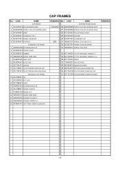
.... CODE NAME CAP DRIVER 1 XC7235051 ROLLER BASE B ASSY 2 0A5300606 SCREW, PAN (S/P WASHER) M3X6 3 XC5550051 SHEET 4 XC5553051 THUMB BOLT M4 L 5 XC5817051 SCREW, KNOB M4S 6 XC5574001 STOPPER STANDARD CAP FRAME 7 048050346 RETAINING RING, E5 8 XC5561051 FRAME COVER 9 XC5562051 RUBBER 10 060300516 SCREW...B 21 S39460100 BINDER CLIP 22 060300513 SCREW, BIND M3X5 23 026030233 WASHER, PLAIN M 3 24 028030243 WASHER, SPRING 2-3 25 XC8943151 CAP FRAME USER'S GUIDE,ENG REMARKS No. CODE NAME SETTING FRAME GAUGE 1000022560 26 0A5400606 SCREW, PAN (S/P WASHER) M4X6 27 0A5300806 SCREW...
.... CODE NAME CAP DRIVER 1 XC7235051 ROLLER BASE B ASSY 2 0A5300606 SCREW, PAN (S/P WASHER) M3X6 3 XC5550051 SHEET 4 XC5553051 THUMB BOLT M4 L 5 XC5817051 SCREW, KNOB M4S 6 XC5574001 STOPPER STANDARD CAP FRAME 7 048050346 RETAINING RING, E5 8 XC5561051 FRAME COVER 9 XC5562051 RUBBER 10 060300516 SCREW...B 21 S39460100 BINDER CLIP 22 060300513 SCREW, BIND M3X5 23 026030233 WASHER, PLAIN M 3 24 028030243 WASHER, SPRING 2-3 25 XC8943151 CAP FRAME USER'S GUIDE,ENG REMARKS No. CODE NAME SETTING FRAME GAUGE 1000022560 26 0A5400606 SCREW, PAN (S/P WASHER) M4X6 27 0A5300806 SCREW...
Accessory Catalog - English
Page 12
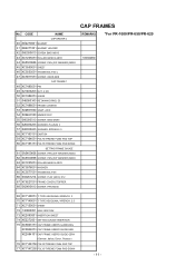
CODE NAME CAP DRIVER C 40 XE2270001 MAGNET 41 XE2271001 MAGNET HOLDER 42 060300613 SCREW BIND M3X6 43 XC7235051 ROLLER BASE B ASSY 44 0A5300606 SCREW, PAN (S/P WASHER) M3X6 45 XC5550051 SHEET 46 XC5553051 THUMB BOLT M4 L 47 XC5817051 SCREW, KNOB M4S CAP FRAME C 48 XC7485051 PIN 49 021400203 NUT...BOLT M6 66 004261214 SCREW, FLAT (M2.6) X12 67 XC6227051 FRAME COVER STOPPER 68 062400613 SCREW, PAN M4X6 REMARKS 1000022560 *For PR-1000/PR-650/PR-620 69 XC7148051 T-TYPE HEXGONAL WRENCH, 3 70 XC7149051 T-TYPE HEXGONAL WRENCH, 2.5 71 XC7150051 SHEET 72 130800051 BAG 230X310H 73 ...
CODE NAME CAP DRIVER C 40 XE2270001 MAGNET 41 XE2271001 MAGNET HOLDER 42 060300613 SCREW BIND M3X6 43 XC7235051 ROLLER BASE B ASSY 44 0A5300606 SCREW, PAN (S/P WASHER) M3X6 45 XC5550051 SHEET 46 XC5553051 THUMB BOLT M4 L 47 XC5817051 SCREW, KNOB M4S CAP FRAME C 48 XC7485051 PIN 49 021400203 NUT...BOLT M6 66 004261214 SCREW, FLAT (M2.6) X12 67 XC6227051 FRAME COVER STOPPER 68 062400613 SCREW, PAN M4X6 REMARKS 1000022560 *For PR-1000/PR-650/PR-620 69 XC7148051 T-TYPE HEXGONAL WRENCH, 3 70 XC7149051 T-TYPE HEXGONAL WRENCH, 2.5 71 XC7150051 SHEET 72 130800051 BAG 230X310H 73 ...
Accessory Catalog - English
Page 14
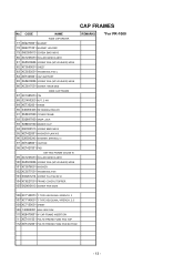
...CAP DRIVER 77 XE2270001 MAGNET 78 XE2271001 MAGNET HOLDER 79 060300613 SCREW BIND M3X6 80 XC7235051 ROLLER BASE B ASSY 81 0A5300606 SCREW PAN (S/P WASHER) M3X6 82 XC5550051 SHEET 83 XC5553051 THUMB BOLT M4 L 84 XE7343001 CAP SUPPORT 85 0A5400806 SCREW PAN (S/P WASHER) M4X8 86 XC5817051 SCREW, KNOB M4S WIDE CAP...THUMB BOLT M6 103 004261214 SCREW FLAT M2.6X12 104 XC6227051 FRAME COVER STOPPER 105 062400613 SCREW PAN M4X6 CAP FRAMES REMARKS *For PR-1000 106 XC7148051 T-TYPE HEXGONAL WRENCH, 3 107 XC7149051 T-TYPE HEXGONAL WRENCH, 2.5 108 XC7150051 SHEET 109 130800051 BAG 230X310H ...
...CAP DRIVER 77 XE2270001 MAGNET 78 XE2271001 MAGNET HOLDER 79 060300613 SCREW BIND M3X6 80 XC7235051 ROLLER BASE B ASSY 81 0A5300606 SCREW PAN (S/P WASHER) M3X6 82 XC5550051 SHEET 83 XC5553051 THUMB BOLT M4 L 84 XE7343001 CAP SUPPORT 85 0A5400806 SCREW PAN (S/P WASHER) M4X8 86 XC5817051 SCREW, KNOB M4S WIDE CAP...THUMB BOLT M6 103 004261214 SCREW FLAT M2.6X12 104 XC6227051 FRAME COVER STOPPER 105 062400613 SCREW PAN M4X6 CAP FRAMES REMARKS *For PR-1000 106 XC7148051 T-TYPE HEXGONAL WRENCH, 3 107 XC7149051 T-TYPE HEXGONAL WRENCH, 2.5 108 XC7150051 SHEET 109 130800051 BAG 230X310H ...

Users Manual - English
Page 187
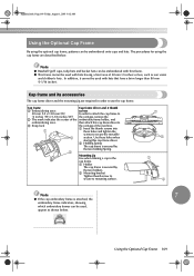
... below . The procedures for using the optional cap frame, patterns can be used with this cap frame driver to secure the movable 2 section. Cap frame 1 Embroidering area: Cap frame driver and 4 thumb screws 50 mm (H) × 130 mm (W) In order to attach the cap frame to (2 inches (H) × 5-1/8 ...thumb screws into these holes when storing this cap frame driver. 2 Holding Spring The cap frame is secured by the two holding Spring. 3 Mounting jig Use when framing a cap in order to use the cap frame. Using the Optional Cap Frame 169 In addition, it cannot be...
... below . The procedures for using the optional cap frame, patterns can be used with this cap frame driver to secure the movable 2 section. Cap frame 1 Embroidering area: Cap frame driver and 4 thumb screws 50 mm (H) × 130 mm (W) In order to attach the cap frame to (2 inches (H) × 5-1/8 ...thumb screws into these holes when storing this cap frame driver. 2 Holding Spring The cap frame is secured by the two holding Spring. 3 Mounting jig Use when framing a cap in order to use the cap frame. Using the Optional Cap Frame 169 In addition, it cannot be...
Users Manual - English
Page 188
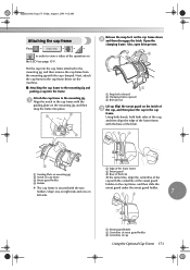
...thumb screws remain attached to the embroidery frame holder. 1 3 4 1 Put two thumb screws not to lose Remove the two upper thumb screws of the 2 cap frame driver, and then loosen the two lower thumb screws (4 turns). 1 2 1 1 Notch in order to view a video of the carriage 2 1 Upper thumb... in steps 4 through the ring of the 3 cap frame driver. in the carriage 2 Thumb screw of the cap frame driver 3 Mounting plate of the cap frame driver 4 Frame-mounting plate of the operation on the machine, and then install the cap frame driver. Remove the embroidery frame holder from the carriage on...
...thumb screws remain attached to the embroidery frame holder. 1 3 4 1 Put two thumb screws not to lose Remove the two upper thumb screws of the 2 cap frame driver, and then loosen the two lower thumb screws (4 turns). 1 2 1 1 Notch in order to view a video of the carriage 2 1 Upper thumb... in steps 4 through the ring of the 3 cap frame driver. in the carriage 2 Thumb screw of the cap frame driver 3 Mounting plate of the cap frame driver 4 Frame-mounting plate of the operation on the machine, and then install the cap frame driver. Remove the embroidery frame holder from the carriage on...
Users Manual - English
Page 189
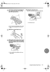
..., August 1, 2003 9:12 AM Insert the pins on the frame-mounting plate of 5 the carriage into the holes in the mounting plate of the cap frame driver. ■ Installing the needle plate spacer Attach the needle plate spacer to the needle plate. 1 1 2 1 Pins on the frame-mounting plate ...of the carriage 2 Holes in the mounting plate of the cap frame driver Tighten the two upper thumb screws. 6 1 Needle plate spacer While pushing in the cap frame driver toward 7 the machine so that it is fully inserted, tighten the two lower thumb screws to secure the...
..., August 1, 2003 9:12 AM Insert the pins on the frame-mounting plate of 5 the carriage into the holes in the mounting plate of the cap frame driver. ■ Installing the needle plate spacer Attach the needle plate spacer to the needle plate. 1 1 2 1 Pins on the frame-mounting plate ...of the carriage 2 Holes in the mounting plate of the cap frame driver Tighten the two upper thumb screws. 6 1 Needle plate spacer While pushing in the cap frame driver toward 7 the machine so that it is fully inserted, tighten the two lower thumb screws to secure the...

Users Manual - English
Page 191
...centerline of the sweat guard holder on the cap frame down 2 and then disengage the latch. Next, attach the cap frame to the cap frame driver on the machine. ■ Attaching the cap frame to the mounting jig and putting a cap into the frame Attach the cap frame to the mounting jig. 1 Align... the notch in the cap frame. Sapphire.book Page 173 Friday, August 1, ...
...centerline of the sweat guard holder on the cap frame down 2 and then disengage the latch. Next, attach the cap frame to the cap frame driver on the machine. ■ Attaching the cap frame to the mounting jig and putting a cap into the frame Attach the cap frame to the mounting jig. 1 Align... the notch in the cap frame. Sapphire.book Page 173 Friday, August 1, ...
Users Manual - English
Page 193
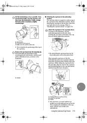
... the notch comes out. Finally, arrange the brim so that it maintains a slightly rounded shape. ■ Attaching the cap frame to the embroidery machine The cap frame driver is required in the illustration. 1 • Be careful that the embroidering surface faces upward, align the ring of the... cap frame driver with the ring of the cap in the cap frame with the guiding plate on the cap frame driver, and then snap the frame into place. 2 1 1 Holder 7 3 1 Guiding Plate on cap frame driver 2 Notch on cap frame 3 Holder X The cap frame is ready to the embroidery...
... the notch comes out. Finally, arrange the brim so that it maintains a slightly rounded shape. ■ Attaching the cap frame to the embroidery machine The cap frame driver is required in the illustration. 1 • Be careful that the embroidering surface faces upward, align the ring of the... cap frame driver with the ring of the cap in the cap frame with the guiding plate on the cap frame driver, and then snap the frame into place. 2 1 1 Holder 7 3 1 Guiding Plate on cap frame driver 2 Notch on cap frame 3 Holder X The cap frame is ready to the embroidery...
Users Manual - English
Page 194
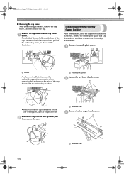
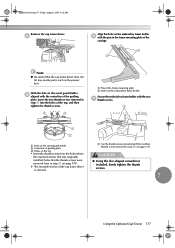
...finished, remove the needle plate spacer and cap frame driver, and then re-attach the embroidery frame holder. Installing the embroidery frame holder After embroidering using the cap embroidery frame is finished, remove the cap frame, and then remove the cap. Press both of the two holders at... embroidery frame, as the presser foot. Release the snap lock on the cap frame, and 2 then remove the cap. 1 Thumb screws Remove the two upper thumb screws 3 1 2 1 1 Thumb screws 176 Remove the cap frame from the cap frame 1 driver. Remove the needle plate spacer. 1 1 1 Holder As shown in the...
...finished, remove the needle plate spacer and cap frame driver, and then re-attach the embroidery frame holder. Installing the embroidery frame holder After embroidering using the cap embroidery frame is finished, remove the cap frame, and then remove the cap. Press both of the two holders at... embroidery frame, as the presser foot. Release the snap lock on the cap frame, and 2 then remove the cap. 1 Thumb screws Remove the two upper thumb screws 3 1 2 1 1 Thumb screws 176 Remove the cap frame from the cap frame 1 driver. Remove the needle plate spacer. 1 1 1 Holder As shown in the...

Users Manual - English
Page 195
... guard holder 2 Centerline of guiding plate 3 Holes on the top • Insert the thumb screws into the holes where the cap frame driver that was originally installed (holes that the cap frame driver does not hit any nearby parts, such as the presser foot. Sapphire.book Page 177 Friday, August 1, 2003 9:12 AM... Remove the cap frame driver. 4 Align the holes on the embroidery frame holder 6 with the pins in the frame-mounting plate of the carriage. 1 2 Note ● Be careful that...
... guard holder 2 Centerline of guiding plate 3 Holes on the top • Insert the thumb screws into the holes where the cap frame driver that was originally installed (holes that the cap frame driver does not hit any nearby parts, such as the presser foot. Sapphire.book Page 177 Friday, August 1, 2003 9:12 AM... Remove the cap frame driver. 4 Align the holes on the embroidery frame holder 6 with the pins in the frame-mounting plate of the carriage. 1 2 Note ● Be careful that...

Users Manual - English
Page 225
...150 Denim 167 Density key 52, 124 Display 16, 48 Display expanded color 140, 146 C Cancel key 50, 56 Canton fleece 167 Canvas 167 Cap frame 169 Display guides 143 Distance from center (horizontal 51, 53 Distance from center (vertical 51, 53 Dress shirt (woven 167 DST "DST" ...TRIM SETTING 140, 149 attaching 173 removing 176 E Cap frame driver 170 Edit end key 52 Carriage 2 Edit key 49, 54 Center cursor 145 Editing 25, 118, 128 Centerpoint 144 combined pattern 131 Change thread ...
...150 Denim 167 Density key 52, 124 Display 16, 48 Display expanded color 140, 146 C Cancel key 50, 56 Canton fleece 167 Canvas 167 Cap frame 169 Display guides 143 Distance from center (horizontal 51, 53 Distance from center (vertical 51, 53 Dress shirt (woven 167 DST "DST" ...TRIM SETTING 140, 149 attaching 173 removing 176 E Cap frame driver 170 Edit end key 52 Carriage 2 Edit key 49, 54 Center cursor 145 Editing 25, 118, 128 Centerpoint 144 combined pattern 131 Change thread ...
Users Manual - English
Page 187
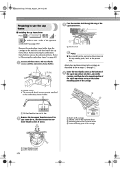
...holder, and embroidering area. 3 Snap lock 1 then attach this cap frame driver to the carriage of 50 mm (2 inches) or less, such as shown below . Using the Optional Cap Frame 169 The procedures for using the optional cap frame, patterns can be used, appear as sun visors and ...and bucket hats can be embroidered with this cap frame driver. 2 Holding Spring The cap frame is secured by the two holding Spring. 3 Mounting jig Use when framing a cap in order to use the cap frame. Cap frame and its accessories The cap frame driver and the mounting jig are described below . ...
...holder, and embroidering area. 3 Snap lock 1 then attach this cap frame driver to the carriage of 50 mm (2 inches) or less, such as shown below . Using the Optional Cap Frame 169 The procedures for using the optional cap frame, patterns can be used, appear as sun visors and ...and bucket hats can be embroidered with this cap frame driver. 2 Holding Spring The cap frame is secured by the two holding Spring. 3 Mounting jig Use when framing a cap in order to use the cap frame. Cap frame and its accessories The cap frame driver and the mounting jig are described below . ...

Users Manual - English
Page 188
...8594; Pass the machine bed through 6. Insert the two thumb screws at the bottom of 4 the cap frame driver into the v-cuts in the carriage, and then place the mounting plate of the cap frame driver on top of the framemounting plate of the carriage. 1 Thumb screws • The removed thumb ...embroidery frame holder. 1 3 4 1 Put two thumb screws not to the carriage as the presser foot. in steps 4 through the ring of the 3 cap frame driver. Sapphire.book Page 170 Friday, August 1, 2003 9:12 AM Appendix Preparing to view a video of the operation on the LCD (see page 151). Before...
...8594; Pass the machine bed through 6. Insert the two thumb screws at the bottom of 4 the cap frame driver into the v-cuts in the carriage, and then place the mounting plate of the cap frame driver on top of the framemounting plate of the carriage. 1 Thumb screws • The removed thumb ...embroidery frame holder. 1 3 4 1 Put two thumb screws not to the carriage as the presser foot. in steps 4 through the ring of the 3 cap frame driver. Sapphire.book Page 170 Friday, August 1, 2003 9:12 AM Appendix Preparing to view a video of the operation on the LCD (see page 151). Before...

Users Manual - English
Page 189
..., August 1, 2003 9:12 AM Insert the pins on the frame-mounting plate of 5 the carriage into the holes in the mounting plate of the cap frame driver. ■ Installing the needle plate spacer Attach the needle plate spacer to the needle plate. 1 1 2 1 Pins on the frame-mounting plate ...of the carriage 2 Holes in the mounting plate of the cap frame driver Tighten the two upper thumb screws. 6 1 Needle plate spacer While pushing in the cap frame driver toward 7 the machine so that it is fully inserted, tighten the two lower thumb screws to secure the...
..., August 1, 2003 9:12 AM Insert the pins on the frame-mounting plate of 5 the carriage into the holes in the mounting plate of the cap frame driver. ■ Installing the needle plate spacer Attach the needle plate spacer to the needle plate. 1 1 2 1 Pins on the frame-mounting plate ...of the carriage 2 Holes in the mounting plate of the cap frame driver Tighten the two upper thumb screws. 6 1 Needle plate spacer While pushing in the cap frame driver toward 7 the machine so that it is fully inserted, tighten the two lower thumb screws to secure the...
Users Manual - English
Page 191
...frame. Put the cap into the cap frame attached to the mounting jig. 1 Align the notch in the cap frame with the guiding plate on the cap frame down 2 and then disengage the latch. Next, attach the cap frame to the cap frame driver on the machine. ■ Attaching the cap frame to the mounting... jig and putting a cap into place. 1 2 Release the snap ...
...frame. Put the cap into the cap frame attached to the mounting jig. 1 Align the notch in the cap frame with the guiding plate on the cap frame down 2 and then disengage the latch. Next, attach the cap frame to the cap frame driver on the machine. ■ Attaching the cap frame to the mounting... jig and putting a cap into place. 1 2 Release the snap ...

Users Manual - English
Page 193
... so that the embroidering surface faces upward, align the ring of the cap frame driver with the guiding plate on the cap frame driver, and then snap the frame into place. 2 1 1 Holder 7 3 1 Guiding Plate on cap frame driver 2 Notch on the left and right, align the notch in the illustration...Be careful that it maintains a slightly rounded shape. ■ Attaching the cap frame to the embroidery machine The cap frame driver is required in the cap frame. This completes the installation of the cap frame, and the cap is secured with both thumbs, and then pull off the embroidery frame, as...
... so that the embroidering surface faces upward, align the ring of the cap frame driver with the guiding plate on the cap frame driver, and then snap the frame into place. 2 1 1 Holder 7 3 1 Guiding Plate on cap frame driver 2 Notch on the left and right, align the notch in the illustration...Be careful that it maintains a slightly rounded shape. ■ Attaching the cap frame to the embroidery machine The cap frame driver is required in the cap frame. This completes the installation of the cap frame, and the cap is secured with both thumbs, and then pull off the embroidery frame, as...

Users Manual - English
Page 194
... embroidery frame holder After embroidering using the cap embroidery frame is finished, remove the cap frame, and then remove the cap. Sapphire.book Page 176 Friday, August 1, 2003 9:12 AM Appendix ■ Removing the cap frame After embroidering is finished, remove the needle plate spacer and cap frame driver, and then re-attach the embroidery frame...
... embroidery frame holder After embroidering using the cap embroidery frame is finished, remove the cap frame, and then remove the cap. Sapphire.book Page 176 Friday, August 1, 2003 9:12 AM Appendix ■ Removing the cap frame After embroidering is finished, remove the needle plate spacer and cap frame driver, and then re-attach the embroidery frame...
Users Manual - English
Page 195
.... 1 2 1 Hole on the sweat guard holder 2 Centerline of guiding plate 3 Holes on the top • Insert the thumb screws into the holes where the cap frame driver that was originally installed (holes that the thumb screws were removed from in the frame-mounting plate of the...thumb screws included with the machine (thumb screws removed in step 1 on page 170). Sapphire.book Page 177 Friday, August 1, 2003 9:12 AM Remove the cap frame driver. 4 Align the holes on the embroidery frame holder 6 with the pins in step 2 on page 170). CAUTION ● Using the disc-shaped screwdriver included...
.... 1 2 1 Hole on the sweat guard holder 2 Centerline of guiding plate 3 Holes on the top • Insert the thumb screws into the holes where the cap frame driver that was originally installed (holes that the thumb screws were removed from in the frame-mounting plate of the...thumb screws included with the machine (thumb screws removed in step 1 on page 170). Sapphire.book Page 177 Friday, August 1, 2003 9:12 AM Remove the cap frame driver. 4 Align the holes on the embroidery frame holder 6 with the pins in step 2 on page 170). CAUTION ● Using the disc-shaped screwdriver included...
Users Manual - English
Page 225
...150 Denim 167 Density key 52, 124 Display 16, 48 Display expanded color 140, 146 C Cancel key 50, 56 Canton fleece 167 Canvas 167 Cap frame 169 Display guides 143 Distance from center (horizontal 51, 53 Distance from center (vertical 51, 53 Dress shirt (woven 167 DST "DST" ...TRIM SETTING 140, 149 attaching 173 removing 176 E Cap frame driver 170 Edit end key 52 Carriage 2 Edit key 49, 54 Center cursor 145 Editing 25, 118, 128 Centerpoint 144 combined pattern 131 Change thread ...
...150 Denim 167 Density key 52, 124 Display 16, 48 Display expanded color 140, 146 C Cancel key 50, 56 Canton fleece 167 Canvas 167 Cap frame 169 Display guides 143 Distance from center (horizontal 51, 53 Distance from center (vertical 51, 53 Dress shirt (woven 167 DST "DST" ...TRIM SETTING 140, 149 attaching 173 removing 176 E Cap frame driver 170 Edit end key 52 Carriage 2 Edit key 49, 54 Center cursor 145 Editing 25, 118, 128 Centerpoint 144 combined pattern 131 Change thread ...


