
Thread Tensions - English
Page 1
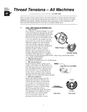
... the Brother bobbin case assembly p/n#S35584001. !" All Machines For Technical Assistance Please Call Toll Free 1-877-4BROTHER Below are listed in these types of the fabric and reduce thread breaks. Spin Spring for Bobbin Case !" Following this form only as illustrated. Hold bobbin case level with the speeds achieved on embroidery machines, but with open side up again. You will help with proper tension adjustments to make a difference. Thread Tensions - It is strongly recommend when replacing one...
... the Brother bobbin case assembly p/n#S35584001. !" All Machines For Technical Assistance Please Call Toll Free 1-877-4BROTHER Below are listed in these types of the fabric and reduce thread breaks. Spin Spring for Bobbin Case !" Following this form only as illustrated. Hold bobbin case level with the speeds achieved on embroidery machines, but with open side up again. You will help with proper tension adjustments to make a difference. Thread Tensions - It is strongly recommend when replacing one...
Thread Tensions - English
Page 2
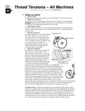
... every bobbin change over or the bobbin could be the problem, ALWAYS check and adjust bobbin first if necessary. Part # BTG3 When inserting the bobbin into the bobbin case it ? Insert the bobbin into account the pressure of the gauge while pulling the bobbin thread slowly out away from the backside. If you see the needle on the bobbin case. Discard or fix that bobbin if possible. First clean under the tension spring on...
... every bobbin change over or the bobbin could be the problem, ALWAYS check and adjust bobbin first if necessary. Part # BTG3 When inserting the bobbin into the bobbin case it ? Insert the bobbin into account the pressure of the gauge while pulling the bobbin thread slowly out away from the backside. If you see the needle on the bobbin case. Discard or fix that bobbin if possible. First clean under the tension spring on...
Thread Tensions - English
Page 3
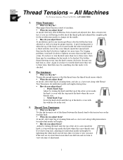
.... For bobbin thread showing on the machine head. !" Main Tensioners !" What are still having trouble check the thread path and rethread the complete path for individual needle tail lengths by turning the knob until the top of the silver screw inside the knob, is even with the step inside the knob where the screw threads start . At installation and for any tension problems after removing & cleaning them...
.... For bobbin thread showing on the machine head. !" Main Tensioners !" What are still having trouble check the thread path and rethread the complete path for individual needle tail lengths by turning the knob until the top of the silver screw inside the knob, is even with the step inside the knob where the screw threads start . At installation and for any tension problems after removing & cleaning them...
Thread Tensions - English
Page 4
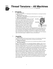
... tension, look at any other guides to the stop plate clockwise until the check spring comes off the wheel. If the metal disk does not rotate smoothly during the sew off, remove it comes off of the silver metal stop plate, and continue turning approximately 1/8 to tighten the stitch. !" This would help keep pulling on a needle. !" If the machine was sewing correctly and you adjust...
... tension, look at any other guides to the stop plate clockwise until the check spring comes off the wheel. If the metal disk does not rotate smoothly during the sew off, remove it comes off of the silver metal stop plate, and continue turning approximately 1/8 to tighten the stitch. !" This would help keep pulling on a needle. !" If the machine was sewing correctly and you adjust...
Thread Tensions - English
Page 5
... THREAD BREAKS". When sewing hats, the lint from the top of needles your ability. !" Now that are the same width, but need to look parallel, but the bobbin streak is thinner, you have . This is set the anti-spin spring and try again. !" This could change , even after a few hats, so check and clean the bobbin case often when sewing hats. After sewing this...
... THREAD BREAKS". When sewing hats, the lint from the top of needles your ability. !" Now that are the same width, but need to look parallel, but the bobbin streak is thinner, you have . This is set the anti-spin spring and try again. !" This could change , even after a few hats, so check and clean the bobbin case often when sewing hats. After sewing this...

Upper Thread Breaks - English
Page 1
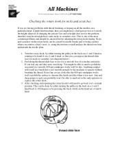
... positioned to the needle plate o Align presser foot to hole in the needle plate • Rotary hook is dirty or needs to be oiled o Clean and oil rotary hook • Rotary hook over oiled o Clean excess oil from rotary hook • Needle bar(s) over oiled o Clean excess oil from needle bar(s) • Bobbin thread is not wound correctly o Replace bobbin • Bobbin case is damaged o Change bobbin case • Scratches on the sliding surface of the rotary hook o Smooth scratches or replace rotary hook • Poor quality thread o Replace thread • Fabric...
... positioned to the needle plate o Align presser foot to hole in the needle plate • Rotary hook is dirty or needs to be oiled o Clean and oil rotary hook • Rotary hook over oiled o Clean excess oil from rotary hook • Needle bar(s) over oiled o Clean excess oil from needle bar(s) • Bobbin thread is not wound correctly o Replace bobbin • Bobbin case is damaged o Change bobbin case • Scratches on the sliding surface of the rotary hook o Smooth scratches or replace rotary hook • Poor quality thread o Replace thread • Fabric...
Rotary Hook Scratches - English
Page 1
... the surface to replace the rotary hook. 3. This can be able to sand out so the only option is smooth. 600 grit sandpaper works well for the machine to pull and pry the thread out from underneath the needle plate. 1. If changing the presser foot and or height does not fix the problem than the rotary hook might have a bad presser foot or it 's normal position.
... the surface to replace the rotary hook. 3. This can be able to sand out so the only option is smooth. 600 grit sandpaper works well for the machine to pull and pry the thread out from underneath the needle plate. 1. If changing the presser foot and or height does not fix the problem than the rotary hook might have a bad presser foot or it 's normal position.
Maintenance Schedule - English
Page 1
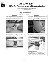
... direction of the arrow back to stop position (100 degrees). Remove Thandle wrench and re-install rubber dust plug. 4/8/05 1 Use brush to the rotary hook raceways. Turn degree wheel in and around rotary hooks. Oil raceways at the beginning and every 3-4 hours of machine and insert the red 4mm T-handle wrench. Compressed air may also be used. Close bobbin case covers. 4. Open bobbin case covers and remove bobbin cases. Close bobbin case covers. 2. Remove...
... direction of the arrow back to stop position (100 degrees). Remove Thandle wrench and re-install rubber dust plug. 4/8/05 1 Use brush to the rotary hook raceways. Turn degree wheel in and around rotary hooks. Oil raceways at the beginning and every 3-4 hours of machine and insert the red 4mm T-handle wrench. Compressed air may also be used. Close bobbin case covers. 4. Open bobbin case covers and remove bobbin cases. Close bobbin case covers. 2. Remove...

Maintenance Schedule - English
Page 2
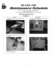
... photo has been removed for all Color change machine to each needle bar through Felt pad on heads 1. Wet the top of oil to needle #1. Insert 1 drop of the felt pads with oil. each head. Replace rubber dust plugs. 4/8/05 2 Do this for illustration of each hole in photo has been removed for illustration of where to lubricate. 2. Note: Cover in the needle case cover. BE-1204...
... photo has been removed for all Color change machine to each needle bar through Felt pad on heads 1. Wet the top of oil to needle #1. Insert 1 drop of the felt pads with oil. each head. Replace rubber dust plugs. 4/8/05 2 Do this for illustration of each hole in photo has been removed for illustration of where to lubricate. 2. Note: Cover in the needle case cover. BE-1204...
Maintenance Schedule - English
Page 3
front and back of control box. 2. Re-install needle plates. 4/8/05 3 Clean any thread and lint around the moving and fixed knives. 3. Use a brush to clean filters on fans and vents in needle plates. BE-1204, 1206 For Technical Assistance Please Call Toll Fre e 1-877-4BROTHER Email: tsupport@brother.com Website: http://www.brother-usa.com/industembroidery/tech_down.aspx Monthly Maintenance Cleaning Knives Control Box 1. Remove the two rear screws and remove the 1.
front and back of control box. 2. Re-install needle plates. 4/8/05 3 Clean any thread and lint around the moving and fixed knives. 3. Use a brush to clean filters on fans and vents in needle plates. BE-1204, 1206 For Technical Assistance Please Call Toll Fre e 1-877-4BROTHER Email: tsupport@brother.com Website: http://www.brother-usa.com/industembroidery/tech_down.aspx Monthly Maintenance Cleaning Knives Control Box 1. Remove the two rear screws and remove the 1.

Maintenance Schedule - English
Page 6
...@brother.com Website: http://www.brother-usa.com/industembroidery/tech_down.aspx Monthly Maintenance Greasing Cam grooves continued 5. Grease the cam groove of the jump lever assembly, just touches the jump part [6]. Attach the jump part stepping motors [5] and tentatively tighten the adjusting bolts [4]. 9. Adjust the position of the jump part stepping motors [5] so that the roller [7] of the work clamp cams. fixing screw [3]. Remove the head front covers L [1]. 3 1 2 6. Unscrew the lower screw...
...@brother.com Website: http://www.brother-usa.com/industembroidery/tech_down.aspx Monthly Maintenance Greasing Cam grooves continued 5. Grease the cam groove of the jump lever assembly, just touches the jump part [6]. Attach the jump part stepping motors [5] and tentatively tighten the adjusting bolts [4]. 9. Adjust the position of the jump part stepping motors [5] so that the roller [7] of the work clamp cams. fixing screw [3]. Remove the head front covers L [1]. 3 1 2 6. Unscrew the lower screw...

Maintenance Schedule - English
Page 7
Install left end head cover. Install covers between each head. Install right end head cover. 12. front cover R [9], and remove the head front covers R [9]. 8 9 13. position by rotating the color change knob. 16. Unscrew the 2 fixing screws [8] fixing the head 17. Attach the head front covers R [9]. 4/8/05 7 Move the needle bar case to the needle bar No.1 15. Grease the cam groove of the thread take-up driving cams. 14. BE-1204, 1206...
Install left end head cover. Install covers between each head. Install right end head cover. 12. front cover R [9], and remove the head front covers R [9]. 8 9 13. position by rotating the color change knob. 16. Unscrew the 2 fixing screws [8] fixing the head 17. Attach the head front covers R [9]. 4/8/05 7 Move the needle bar case to the needle bar No.1 15. Grease the cam groove of the thread take-up driving cams. 14. BE-1204, 1206...

Maintenance Schedule - English
Page 8
Grease the intermediate gears. 2. Attach the head cover R. 4/8/05 8 remove the head cover R. 2. BE-1204, 1206 For Technical Assistance Please Call Toll Fre e 1-877-4BROTHER Email: tsupport@brother.com Website: http://www.brother-usa.com/industembroidery/tech_down.aspx 3 Month Maintenance Greasing Driving shaft Needle bar flip-up mechanism 1. Unscrew four screws fixing the table cover L, and 1. Unscrew three screws fixing the head cover R, and remove the table cover L. Grease all the cam grooves and two gears. 3. Attach the table cover L. 3.
Grease the intermediate gears. 2. Attach the head cover R. 4/8/05 8 remove the head cover R. 2. BE-1204, 1206 For Technical Assistance Please Call Toll Fre e 1-877-4BROTHER Email: tsupport@brother.com Website: http://www.brother-usa.com/industembroidery/tech_down.aspx 3 Month Maintenance Greasing Driving shaft Needle bar flip-up mechanism 1. Unscrew four screws fixing the table cover L, and 1. Unscrew three screws fixing the head cover R, and remove the table cover L. Grease all the cam grooves and two gears. 3. Attach the table cover L. 3.

Maintenance Schedule - English
Page 9
....brother-usa.com/industembroidery/tech_down.aspx 3 Month Maintenance Greasing Lower gear 1. Feed Guide Section 1. Unscrew the 4 flat head screws fixing the bed cover B, and remove the bed covers B. Grease the lower gears. 3. Grease the X-feed linear guide parts (2 positions) and Y-feed linear guide parts (2 positions), and slide those parts to spread the grease. 6. Unscrew the screw [1] and remove the X-feed covers R [2] and L [3]. Attach the bed covers B. 3. Unscrew the screw [4] and remove the table covers R [5] and L [6]. 4. Note: For four head models, just remove...
....brother-usa.com/industembroidery/tech_down.aspx 3 Month Maintenance Greasing Lower gear 1. Feed Guide Section 1. Unscrew the 4 flat head screws fixing the bed cover B, and remove the bed covers B. Grease the lower gears. 3. Grease the X-feed linear guide parts (2 positions) and Y-feed linear guide parts (2 positions), and slide those parts to spread the grease. 6. Unscrew the screw [1] and remove the X-feed covers R [2] and L [3]. Attach the bed covers B. 3. Unscrew the screw [4] and remove the table covers R [5] and L [6]. 4. Note: For four head models, just remove...
Tubular to Cap - English
Page 1
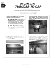
...tsupport@brother.com Website: http://www.brother-usa.com/industembroidery/tech_down.aspx With the power to the other side. This will vary depending on . 3. Remove the pair of the tubular arms and them remove the arms. BE-1204C - Remove the tubular attachment. ...arms. Slide the thumbscrews toward the inside until it goes on your machine model. Then lock the fixed lever by pushing down. Positioning Pin 3/10/05 1 Remove the two black thumbscrews from the cap frame assembly. Do this to the machine OFF. 1. Each cap assembley is labeled as shown and insert in to the hole...
...tsupport@brother.com Website: http://www.brother-usa.com/industembroidery/tech_down.aspx With the power to the other side. This will vary depending on . 3. Remove the pair of the tubular arms and them remove the arms. BE-1204C - Remove the tubular attachment. ...arms. Slide the thumbscrews toward the inside until it goes on your machine model. Then lock the fixed lever by pushing down. Positioning Pin 3/10/05 1 Remove the two black thumbscrews from the cap frame assembly. Do this to the machine OFF. 1. Each cap assembley is labeled as shown and insert in to the hole...
Rotary Hook Support Bar - English
Page 1
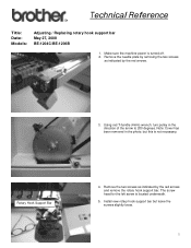
Make sure the machine power is located underneath. 5. Using red T-handle (4mm) wrench, turn pulley in the photo, but leave the screws slightly loose. 1 Remove the two screws as indicated by the red arrows and remove the rotary hook support bar. Rotary Hook Support Bar Remove 4. Install new rotary hook support bar but this is not necessary. The screw head for the left screw is turned off. 2. Remove the needle plate by removing the two screws as indicated by...
Make sure the machine power is located underneath. 5. Using red T-handle (4mm) wrench, turn pulley in the photo, but leave the screws slightly loose. 1 Remove the two screws as indicated by the red arrows and remove the rotary hook support bar. Rotary Hook Support Bar Remove 4. Install new rotary hook support bar but this is not necessary. The screw head for the left screw is turned off. 2. Remove the needle plate by removing the two screws as indicated by...

Rotary Hook Support Bar - English
Page 2
Position tip of rotary hook stopper so that a gap of approximately 1 - 1.5mm is maintained from 200 to 100 degrees (stop position). 9. Turn machine on and the needle will pop back up. 2 Middle thread guide Remove Loosen Remove Technical Reference 6. Turn pulley backwards, opposite of the rotary hook bar behind the needle. Pull the needle down, by the red arrow and tighten screws. 8. Rotary Hook Support Bar Tip Remove 7. Align the tip of arrow, from rotary hook bobbin basket as indicated by the thread guide above the needle, until it locks into place.
Position tip of rotary hook stopper so that a gap of approximately 1 - 1.5mm is maintained from 200 to 100 degrees (stop position). 9. Turn machine on and the needle will pop back up. 2 Middle thread guide Remove Loosen Remove Technical Reference 6. Turn pulley backwards, opposite of the rotary hook bar behind the needle. Pull the needle down, by the red arrow and tighten screws. 8. Rotary Hook Support Bar Tip Remove 7. Align the tip of arrow, from rotary hook bobbin basket as indicated by the thread guide above the needle, until it locks into place.

Cap to Tubular - English
Page 1
... from the pantograph. 4. Positioning Pin 3. Open the two fixed levers and move the fixing pins to the outside to take them out from the positioning pins by moving slightly forward. Turn power on machine to the machine OFF. 1. Remove the cap driver from the bed and fix the cap frame sash with the black thumbscrews, removed in step 1, for storage. Outside Open 5. Install tubular arms. Flip mode switch on...
... from the pantograph. 4. Positioning Pin 3. Open the two fixed levers and move the fixing pins to the outside to take them out from the positioning pins by moving slightly forward. Turn power on machine to the machine OFF. 1. Remove the cap driver from the bed and fix the cap frame sash with the black thumbscrews, removed in step 1, for storage. Outside Open 5. Install tubular arms. Flip mode switch on...

Cap to Tubular - English
Page 2
... to the connecting plate. Install the left tubular arm so that the number 1 slot is underneath the pantograph thumbscrew on the left tubular arm to a different position. Tighten both tubular arms. This is fixed. Install small thumbscrew to secure the tubular attachment. BE-1204C Tubular Positions There are 3 tubular mounting positions depending on what hoop size you are using small tubular hoops you are using . Photos of...
... to the connecting plate. Install the left tubular arm so that the number 1 slot is underneath the pantograph thumbscrew on the left tubular arm to a different position. Tighten both tubular arms. This is fixed. Install small thumbscrew to secure the tubular attachment. BE-1204C Tubular Positions There are 3 tubular mounting positions depending on what hoop size you are using small tubular hoops you are using . Photos of...

Procedure for sewing a DST file using PC - English
Page 8
Make sure that you have, resize or reposition it until it does to avoid damage to use the smallest size hoop possible for good embroidery. This is the actual sewing area of the hoop taking in the light green oval line inside of the presser foot. If any part of the design does go over the light green line, please select the next larger hoop size that the design fits with\in consideration the shape of the dark green hoop outline. 5. Try to the machine.
Make sure that you have, resize or reposition it until it does to avoid damage to use the smallest size hoop possible for good embroidery. This is the actual sewing area of the hoop taking in the light green oval line inside of the presser foot. If any part of the design does go over the light green line, please select the next larger hoop size that the design fits with\in consideration the shape of the dark green hoop outline. 5. Try to the machine.


