
Hand Book - English
Page 1
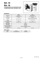
Rear loading DC motor Vibration bowl, front-back discrimination Available TQ × 1 #16 TQ × 1 #12 Part name Starter device assembly Part code S05462-009 2000.7 BA-10, BA-16 1/5 of stitches (X × Y) Feed length Button clamp lifter stroke Button type Button diameter Button feed time Button loading Power source of the feeder Button arrangement Button feed error detector Needle Starter device Model BA-10 BA-10 CB3-B917A Chainstitch button sewer 1,500 rpm 8 16 32 6 12 24 BA-16 LK3-B448E Mark II...
Rear loading DC motor Vibration bowl, front-back discrimination Available TQ × 1 #16 TQ × 1 #12 Part name Starter device assembly Part code S05462-009 2000.7 BA-10, BA-16 1/5 of stitches (X × Y) Feed length Button clamp lifter stroke Button type Button diameter Button feed time Button loading Power source of the feeder Button arrangement Button feed error detector Needle Starter device Model BA-10 BA-10 CB3-B917A Chainstitch button sewer 1,500 rpm 8 16 32 6 12 24 BA-16 LK3-B448E Mark II...

Network Users Manual - English
Page 2
... ( Main Part Names 1 (Installation J 2 EllIECIEDOCIE1111 Work table preparation 2 Starter 2 Vibration bowl 3 Control box 3 Sewing machine head 3 Button feeder 4 Cord connections 4 Cover 6 Shooter 6 Starter connecting rod and operating lever 6 E Standard specifications model modifications 7 ( Adjustments) 8 M Button feeder adjustments 8 1. DC motor, worm, worm wheel backlash 16 11. Crossover-stitch selector 20 5. Control circuit board adjustments 23 Parts Replacement ) 24 M Control circuit board 24 M Power circuit board 25 ( Troubleshooting Guide...
... ( Main Part Names 1 (Installation J 2 EllIECIEDOCIE1111 Work table preparation 2 Starter 2 Vibration bowl 3 Control box 3 Sewing machine head 3 Button feeder 4 Cord connections 4 Cover 6 Shooter 6 Starter connecting rod and operating lever 6 E Standard specifications model modifications 7 ( Adjustments) 8 M Button feeder adjustments 8 1. DC motor, worm, worm wheel backlash 16 11. Crossover-stitch selector 20 5. Control circuit board adjustments 23 Parts Replacement ) 24 M Control circuit board 24 M Power circuit board 25 ( Troubleshooting Guide...

Network Users Manual - English
Page 4
... mounting screw (1 screw). * Be sure the starter connecting rod Q is on . ( Installation ) Please be sure to prepare the work table for sewing machine installation. (The lower hole for the control box power switch should be 03 and about 30 mm deep; In case that for the starter should be 04 dia. Nk 51.3 Control box position 535 Lower hole 4-03 Switch position -1 207+0.2 ± 0.3 125 35 Button feeder mounting hole Lower hole...
... mounting screw (1 screw). * Be sure the starter connecting rod Q is on . ( Installation ) Please be sure to prepare the work table for sewing machine installation. (The lower hole for the control box power switch should be 03 and about 30 mm deep; In case that for the starter should be 04 dia. Nk 51.3 Control box position 535 Lower hole 4-03 Switch position -1 207+0.2 ± 0.3 125 35 Button feeder mounting hole Lower hole...

Network Users Manual - English
Page 9
Replace the button clamp. t The crossover-stitch attachment cannot be replaced or installed when using a standard specifications B917 sewing machine. Replace the sewing machine bed table. 2. El Standard specification model modifications * The following parts must be installed with model B917. 1.
Replace the button clamp. t The crossover-stitch attachment cannot be replaced or installed when using a standard specifications B917 sewing machine. Replace the sewing machine bed table. 2. El Standard specification model modifications * The following parts must be installed with model B917. 1.
Network Users Manual - English
Page 13
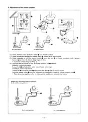
... STITCHES CD 0 ED MANUAL 1-57)1., TROUBLE 0 brother BA -10 Crd cZ) 0 CD For 2-hole button CD 0 For 4-hole button (1) Check whether or not the feeder switch Q is completed to return the button transport arm Q. * Turn the sewing machine pulley to rise.) * Assist the button clamp by lifting up or down and arm 0 front or back to adjust. Right/left position adjustment Loosen bolt 0 and adjust the entire button feeder left or right. sewing patterns...
... STITCHES CD 0 ED MANUAL 1-57)1., TROUBLE 0 brother BA -10 Crd cZ) 0 CD For 2-hole button CD 0 For 4-hole button (1) Check whether or not the feeder switch Q is completed to return the button transport arm Q. * Turn the sewing machine pulley to rise.) * Assist the button clamp by lifting up or down and arm 0 front or back to adjust. Right/left position adjustment Loosen bolt 0 and adjust the entire button feeder left or right. sewing patterns...
Network Users Manual - English
Page 14
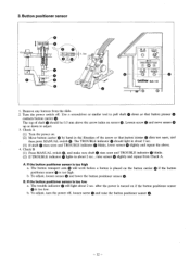
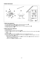
... to adjust. 3. Loosen screw 0 and move sensor 0 up or down so that button presser 0 contacts button carrier The top of the arrow so that button carrier 0 doe's not open, and then press MANUAL switch 0. The TROUBLE indicator 0 should be 0.5 mm above . 4. Button positioner sensor O po O O 0 0 . 5mm 0 O I• POWER 0 ❑1•vF ROBOT ON (!).) OFF CROSS-OVER STITCHES @0 @ 4 tD MANUAL -5- 71l, TROUBLE brother BA -10 a 1. If the button positioner...
... to adjust. 3. Loosen screw 0 and move sensor 0 up or down so that button presser 0 contacts button carrier The top of the arrow so that button carrier 0 doe's not open, and then press MANUAL switch 0. The TROUBLE indicator 0 should be 0.5 mm above . 4. Button positioner sensor O po O O 0 0 . 5mm 0 O I• POWER 0 ❑1•vF ROBOT ON (!).) OFF CROSS-OVER STITCHES @0 @ 4 tD MANUAL -5- 71l, TROUBLE brother BA -10 a 1. If the button positioner...
Network Users Manual - English
Page 19
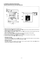
... parts are not firmly secured. (Use a 1.0 mm thick spring Q for 60 Hz models, and a 0.8 mm thick spring for 50 Hz models.) 4. VI.ATOR ON OFF 0 0 brother BA-10 1. Adjust the bowl carrier 0 bottom to the maximum vibration setting. 6. Lower the vibration solenoid so that the noise goes away, and then firmly tighten nut G. The bowl will be emitted. Press the power switch, and set...
... parts are not firmly secured. (Use a 1.0 mm thick spring Q for 60 Hz models, and a 0.8 mm thick spring for 50 Hz models.) 4. VI.ATOR ON OFF 0 0 brother BA-10 1. Adjust the bowl carrier 0 bottom to the maximum vibration setting. 6. Lower the vibration solenoid so that the noise goes away, and then firmly tighten nut G. The bowl will be emitted. Press the power switch, and set...

Network Users Manual - English
Page 20
... swings below the needle. (3) Tighten bolt Q at the center of the oval hole in solenoid base Q. 0 Q (4) Loosen bolt Q and adjust the needle center to thread wiper tip gap to page 7, stop switch installation. (2) When the sewing machine is moved all the way in the stop position (presser foot raised), make sure whethe the sensor support plate 0 interrupts the light beam for the stop sensor Q. 0 2. Sewing machine head adjustments 1.
... swings below the needle. (3) Tighten bolt Q at the center of the oval hole in solenoid base Q. 0 Q (4) Loosen bolt Q and adjust the needle center to thread wiper tip gap to page 7, stop switch installation. (2) When the sewing machine is moved all the way in the stop position (presser foot raised), make sure whethe the sensor support plate 0 interrupts the light beam for the stop sensor Q. 0 2. Sewing machine head adjustments 1.
Network Users Manual - English
Page 21
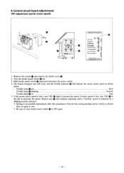
... ON • OFF WO* CROSS-OVER STITCHES @0 @ # MANUAL TROUBLE 0 brother BA- 1 0 ▪ OC, 1. when there is no button in the button clamp Q. (3) Loosen bolt 0 and move the sensor mount G in the direction of the arrow until the trouble indicator blinks. (4) Tighten bolt G. (5) Insert a button into the button clamp Q. (2) Lightly tighten adjustment screw 0, and remove the button. (3) Decrease the button clamp Q opening 1.0 mm to 0.5 mm with adjustment lever G (4) Tighten adjustment screw Q. 2. 3. bV "k .0 to the arrow until the...
... ON • OFF WO* CROSS-OVER STITCHES @0 @ # MANUAL TROUBLE 0 brother BA- 1 0 ▪ OC, 1. when there is no button in the button clamp Q. (3) Loosen bolt 0 and move the sensor mount G in the direction of the arrow until the trouble indicator blinks. (4) Tighten bolt G. (5) Insert a button into the button clamp Q. (2) Lightly tighten adjustment screw 0, and remove the button. (3) Decrease the button clamp Q opening 1.0 mm to 0.5 mm with adjustment lever G (4) Tighten adjustment screw Q. 2. 3. bV "k .0 to the arrow until the...
Network Users Manual - English
Page 25
... STITCHES go° C(4` NBNULL F-57/1. Trouble lamp Q out Slow Trouble lamp Q blinking Normal Trouble lamp Q on again to sew. * Be sure to reset feeder panel switch Q to increase the speed; Repeat step and continue adjusting until a "Normal" speed is indicated by a blinking trouble indicator. * Sewing is fast, turn VR1 Q right to ON again. First bet the sewing machine power switch to decrease the speed. TROUBLE brother BA-10 on00000000i...
... STITCHES go° C(4` NBNULL F-57/1. Trouble lamp Q out Slow Trouble lamp Q blinking Normal Trouble lamp Q on again to sew. * Be sure to reset feeder panel switch Q to increase the speed; Repeat step and continue adjusting until a "Normal" speed is indicated by a blinking trouble indicator. * Sewing is fast, turn VR1 Q right to ON again. First bet the sewing machine power switch to decrease the speed. TROUBLE brother BA-10 on00000000i...

Network Users Manual - English
Page 28
Machine stop sensor replacement (1) Remove the starter sensor support. (See page 15, Parts Book, No. 4-2.) (2) Disconnect the connector pins. (3) Disconnect the machine stop sensor complete. (See page 15, Parts Book, No. 4-1) (4) Readjust after replacing the sensor. Button positioner sensor replacement (1) Remove the main cover. (See page 5, Part Book, No. 2) (2) Remove the sensor panel. (See page 10, Parts Book, No. 1-3-4-1.) (3) Disconnect the connector pins. (4) Remove the button positioner sensor complete. (See page 10, Parts Book, No. 1-3-4-2.) (5) Readjust after replacing the...
Machine stop sensor replacement (1) Remove the starter sensor support. (See page 15, Parts Book, No. 4-2.) (2) Disconnect the connector pins. (3) Disconnect the machine stop sensor complete. (See page 15, Parts Book, No. 4-1) (4) Readjust after replacing the sensor. Button positioner sensor replacement (1) Remove the main cover. (See page 5, Part Book, No. 2) (2) Remove the sensor panel. (See page 10, Parts Book, No. 1-3-4-1.) (3) Disconnect the connector pins. (4) Remove the button positioner sensor complete. (See page 10, Parts Book, No. 1-3-4-2.) (5) Readjust after replacing the...
Network Users Manual - English
Page 29
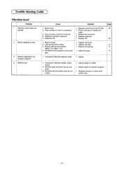
... 17 17 17 1. Shooter size and button size do not match 1. Cause 1. Wrong leaf spring installed (60Hz, t1.2; 50Hz, t1.0) 4. Adjust. Improperly adjusted height, width plates 2. Adjust height or width. 1. ( Trouble shooting Guide ) Vibration bowl Problem 1 Vibration bowl does not vibrate. 2 Button feeding is loose 2. Shooter gate and bowl top are not even 3. Excessive bowl support to match with button size. Replace the terminal. 1. Leaf spring bolt is loose 3. Defective VR 1.
... 17 17 17 1. Shooter size and button size do not match 1. Cause 1. Wrong leaf spring installed (60Hz, t1.2; 50Hz, t1.0) 4. Adjust. Improperly adjusted height, width plates 2. Adjust height or width. 1. ( Trouble shooting Guide ) Vibration bowl Problem 1 Vibration bowl does not vibrate. 2 Button feeding is loose 2. Shooter gate and bowl top are not even 3. Excessive bowl support to match with button size. Replace the terminal. 1. Leaf spring bolt is loose 3. Defective VR 1.
Network Users Manual - English
Page 30
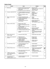
...screw. 13 6. Improperly positioned button carrier 1. Adjust needle location and pin 11 position. 7. Do not use 1. Power circuit board fuse F6 (4A). 25 1. Adjust so the end of the button stopper enters between button positioner 1. Adjust the sensor. 12 even though button is approx. 13 D,) 4 Button not fed to clamp. 1. Replace with cover and spacers for the buttons in use the crossover stitch selector with button clamp 1. Improperly adjusted button 1. Defective button clamp 2. Replace motor. 8 function. 2. Improperly adjusted button 1. Improperly adjusted...
...screw. 13 6. Improperly positioned button carrier 1. Adjust needle location and pin 11 position. 7. Do not use 1. Power circuit board fuse F6 (4A). 25 1. Adjust so the end of the button stopper enters between button positioner 1. Adjust the sensor. 12 even though button is approx. 13 D,) 4 Button not fed to clamp. 1. Replace with cover and spacers for the buttons in use the crossover stitch selector with button clamp 1. Improperly adjusted button 1. Defective button clamp 2. Replace motor. 8 function. 2. Improperly adjusted button 1. Improperly adjusted...

Network Users Manual - English
Page 31
... presser foot 1. Crossover stitch solenoid defect or 1. Adjust switch. 19 trouble indicator still lights. switch 2. Improperly adjusted stroke 1. Defective switch or short 1. Improperly adjusted button feeder 1. Adjust so the lever will move of its 20 lifter lever own weight. 2. Wiper solenoid defect or short 1. base installation. 5 Crossover stitch selector 1. short 2. Replace pin connector. Replace switch. 26 does not function. 2. Adjust button clamp. 19 width 3. Presser bar lifter drive lever and pin 1. Loose screw 2. Replace pin...
... presser foot 1. Crossover stitch solenoid defect or 1. Adjust switch. 19 trouble indicator still lights. switch 2. Improperly adjusted stroke 1. Defective switch or short 1. Improperly adjusted button feeder 1. Adjust so the lever will move of its 20 lifter lever own weight. 2. Wiper solenoid defect or short 1. base installation. 5 Crossover stitch selector 1. short 2. Replace pin connector. Replace switch. 26 does not function. 2. Adjust button clamp. 19 width 3. Presser bar lifter drive lever and pin 1. Loose screw 2. Replace pin...

Network Users Manual - English
Page 32
... Problem Cause Trouble indicator lights when power switch is not fed to shooter? 1. Corroded or shorted feeder power switch 3. Button in vibration bowl solenoid 3. Improperly adjusted button positioner switch 2. Button clamp height, carrier motor gear adjustment 1. Start switch stroke 1. Power outlet, power connector 2. Improper feeder adjustment 4. Blown fuse Power switch ON but feeder panel power indicator does not light. 1. Short in button clamp but cannot sew. Starter solenoid stroke 1. Replace bulb. 1. Is trouble indicator blinking? 1. Adjust...
... Problem Cause Trouble indicator lights when power switch is not fed to shooter? 1. Corroded or shorted feeder power switch 3. Button in vibration bowl solenoid 3. Improperly adjusted button positioner switch 2. Button clamp height, carrier motor gear adjustment 1. Start switch stroke 1. Power outlet, power connector 2. Improper feeder adjustment 4. Blown fuse Power switch ON but feeder panel power indicator does not light. 1. Short in button clamp but cannot sew. Starter solenoid stroke 1. Replace bulb. 1. Is trouble indicator blinking? 1. Adjust...

Parts Manual - Multi
Page 3
... 36 R. Notes for using this parts book 1. Parts supplied as complete assemblies are subject to changes in June 1990. 3. Needle bar and driving clutch mechanism 6 E. Threading mechanism 16 K. Control box mechanism 38 S . Accessories (Option Parts) 42 Z2. Feed mechanism 8 F . Starting device mechanism 22 P1. Crossover stitch mechanism 20 N. Button feeder mechanism 28 P3. Button detector mechanism 38 T. Lower shaft mechanism 14 H. Thread trimmer mechanism 14 J . Power supply equipment mechanism 40...
... 36 R. Notes for using this parts book 1. Parts supplied as complete assemblies are subject to changes in June 1990. 3. Needle bar and driving clutch mechanism 6 E. Threading mechanism 16 K. Control box mechanism 38 S . Accessories (Option Parts) 42 Z2. Feed mechanism 8 F . Starting device mechanism 22 P1. Crossover stitch mechanism 20 N. Button feeder mechanism 28 P3. Button detector mechanism 38 T. Lower shaft mechanism 14 H. Thread trimmer mechanism 14 J . Power supply equipment mechanism 40...

Parts Manual - Multi
Page 14
... ADJUST SCREW TRANSVERSE FEED PLATE TRANSVERSE FEED ADJUST NUT BACK & FORTH FEED ADJUST ASSEMBLY BACK & FORTH ADJUST BLOCK ROLLER SHAFT ROLLER FEED LEVER SHAFT SET SCREW 5.95 BACK & FORTH FEED LEVER SHAFT SET SCREW 5.95 FEED LEVER SHAFT COLLAR (5) SET SCREW 5.95 BACK & FORTH LENGTH CONTROL PLATE SCREW 476X10 POSITIONING PIN PRESSER ARM ASSEMBLY 917B PRESSER ARM PRESSER ADJUST PLATE ASSEMBLY WASHER 6 BOLT 6X10 BUTTON CLAMP ASSEMBLY 917B BUTTON CLAMP BRACKET BUTTON CLAMP (L) PLATE SPRING -8- mechanism/Transportvorrichtung/ Mecanisme de lentrainement/Mecanismo de la alimentation REF.NO. CODE...
... ADJUST SCREW TRANSVERSE FEED PLATE TRANSVERSE FEED ADJUST NUT BACK & FORTH FEED ADJUST ASSEMBLY BACK & FORTH ADJUST BLOCK ROLLER SHAFT ROLLER FEED LEVER SHAFT SET SCREW 5.95 BACK & FORTH FEED LEVER SHAFT SET SCREW 5.95 FEED LEVER SHAFT COLLAR (5) SET SCREW 5.95 BACK & FORTH LENGTH CONTROL PLATE SCREW 476X10 POSITIONING PIN PRESSER ARM ASSEMBLY 917B PRESSER ARM PRESSER ADJUST PLATE ASSEMBLY WASHER 6 BOLT 6X10 BUTTON CLAMP ASSEMBLY 917B BUTTON CLAMP BRACKET BUTTON CLAMP (L) PLATE SPRING -8- mechanism/Transportvorrichtung/ Mecanisme de lentrainement/Mecanismo de la alimentation REF.NO. CODE...

Parts Manual - Multi
Page 18
...,"',5--"€d" 1 7fil-)4:_/"5.95 PRESSER DRIVING LEVER PRESSER CONNECTING STUD SET SCREW 4.37 TENSION RELEASE CONNECTING ROD ASSEMBLY TENSION RELEASE ADJUST STUD STOP RING E5 SET SCREW 4.37 PRESSER BAR LIFTER BRACKET PRESSER LIFTER ARM CLAW ADJIST PLATE SCREW 635X8 PLAIN WASHER 6 BUTTON CPERER CLAW (B) BOLT 4.76X7 WASHER PRESSER LIFTER ARM STUD SET SCREW 5.95 1 *ti "t°) 1 t511"71"*174.37 1 !./.)(4. 4.37 PIN PLAIN WASHER 4.37 SCREW 4.37 - 12 - CODE Q'TY t::.i-r NAME OF PARTS 1 1-1 2 3 4 5 5-1 6 6-1 6-2 6-3 6-4 6-4-1 6-4-2 6-5 6-6 7 9 10 11 11-1 13...
...,"',5--"€d" 1 7fil-)4:_/"5.95 PRESSER DRIVING LEVER PRESSER CONNECTING STUD SET SCREW 4.37 TENSION RELEASE CONNECTING ROD ASSEMBLY TENSION RELEASE ADJUST STUD STOP RING E5 SET SCREW 4.37 PRESSER BAR LIFTER BRACKET PRESSER LIFTER ARM CLAW ADJIST PLATE SCREW 635X8 PLAIN WASHER 6 BUTTON CPERER CLAW (B) BOLT 4.76X7 WASHER PRESSER LIFTER ARM STUD SET SCREW 5.95 1 *ti "t°) 1 t511"71"*174.37 1 !./.)(4. 4.37 PIN PLAIN WASHER 4.37 SCREW 4.37 - 12 - CODE Q'TY t::.i-r NAME OF PARTS 1 1-1 2 3 4 5 5-1 6 6-1 6-2 6-3 6-4 6-4-1 6-4-2 6-5 6-6 7 9 10 11 11-1 13...
Parts Manual - Multi
Page 32
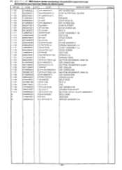
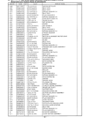
CODE Q'TY t=ot-r NAME OF PARTS 1-100 1-101 1-102 1-103 1-104 1-105 1-106 1-107 1-108 1-111 1-112 1-113 1-114 1-...SET SCREW 6X6 CAM SUPPOTING (B)ARM, PIN WASHER STOP RING E6 SET SCREW 6X6 CAM SUPPORT STUD SCREW M4 NUT 4 JOINT ASSEMBLY (R) NUT 5.95 STUD SCREW NUT 4 PLAIN WASHER 4 SPRING WASHER 2-4 JOINT ASSEMBLY (L) STUD SCREW NUT 5.95 SPRING (A) SPRING HOOK BUTTON MOVEMENT ARM (B) SET SCREW 6X6 BUTTON TRANSPORT SHAFT SET COLLAR SET SCREW 6X6 BUTTON MOVEMENT ARM (A) SET SCREW 6X6 SCREW 3.57X4 BOLT 6X25 NUT 6 PIN SET SCREW 5.95 CONNECTION SHAFT BUTTON CATCH PLATE ASSEMBLY BOLT 6X50 WASHER SPRING...
CODE Q'TY t=ot-r NAME OF PARTS 1-100 1-101 1-102 1-103 1-104 1-105 1-106 1-107 1-108 1-111 1-112 1-113 1-114 1-...SET SCREW 6X6 CAM SUPPOTING (B)ARM, PIN WASHER STOP RING E6 SET SCREW 6X6 CAM SUPPORT STUD SCREW M4 NUT 4 JOINT ASSEMBLY (R) NUT 5.95 STUD SCREW NUT 4 PLAIN WASHER 4 SPRING WASHER 2-4 JOINT ASSEMBLY (L) STUD SCREW NUT 5.95 SPRING (A) SPRING HOOK BUTTON MOVEMENT ARM (B) SET SCREW 6X6 BUTTON TRANSPORT SHAFT SET COLLAR SET SCREW 6X6 BUTTON MOVEMENT ARM (A) SET SCREW 6X6 SCREW 3.57X4 BOLT 6X25 NUT 6 PIN SET SCREW 5.95 CONNECTION SHAFT BUTTON CATCH PLATE ASSEMBLY BOLT 6X50 WASHER SPRING...
Parts Manual - Multi
Page 34
... WASHER BUTTON ALIGNMENT MOTOR GEAR SCREW 3X4 GUIDE BOLT 4X10 SCREW 3X8 SPRING WASHER 2-3 PRESSER BAR CLANK ASSEMBLY SPRING SPRING HOOK SOLENPID SET PLATE BOLT 4X10 SPRING WASHER 2-4 PLAIN WASHER 4 SOLENOID ARM STUD SCREW M4 PLUNGER PIN WIRE STUD SCREW M4 SCREW 3.5X8 ROLLER BOLT 4X10 PLAIN WASHER 4 SPRING WASHER 2-4 STUD SCREW M4 SPRING SPRING HOOK PLUNGER PIN B PANEL ASSEMBLY CURCUIT BOARD ASSEMBLY BOARD SET PLATE SUPPORT 6NS WASHER SCREW 4X8 BUTTON SOLENOID ASSEMBLY BOLT 4X8 SPRING WASHER 2-4 PLAIN WASHER 4 CORD HOLDER SOLENOID BASE CATCH PLATE DRIVING LEVER DRIVING LEVER...
... WASHER BUTTON ALIGNMENT MOTOR GEAR SCREW 3X4 GUIDE BOLT 4X10 SCREW 3X8 SPRING WASHER 2-3 PRESSER BAR CLANK ASSEMBLY SPRING SPRING HOOK SOLENPID SET PLATE BOLT 4X10 SPRING WASHER 2-4 PLAIN WASHER 4 SOLENOID ARM STUD SCREW M4 PLUNGER PIN WIRE STUD SCREW M4 SCREW 3.5X8 ROLLER BOLT 4X10 PLAIN WASHER 4 SPRING WASHER 2-4 STUD SCREW M4 SPRING SPRING HOOK PLUNGER PIN B PANEL ASSEMBLY CURCUIT BOARD ASSEMBLY BOARD SET PLATE SUPPORT 6NS WASHER SCREW 4X8 BUTTON SOLENOID ASSEMBLY BOLT 4X8 SPRING WASHER 2-4 PLAIN WASHER 4 CORD HOLDER SOLENOID BASE CATCH PLATE DRIVING LEVER DRIVING LEVER...


