SL2 wireless surround link - Owner's guide
Page 4
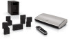
...of the parts shown (Figure 1). Running cable from your authorized Bose dealer immediately. Figure 1 Carton contents Unpacking the carton Carefully unpack the carton and save all of the room is unnecessary. Notify Bose or your LIFESTYLE® system or powered Acoustimass® system. It provides a... simple and convenient means to enjoy the surround sound from the front to surround speakers in the rear of your system includes all packing...
...of the parts shown (Figure 1). Running cable from your authorized Bose dealer immediately. Figure 1 Carton contents Unpacking the carton Carefully unpack the carton and save all of the room is unnecessary. Notify Bose or your LIFESTYLE® system or powered Acoustimass® system. It provides a... simple and convenient means to enjoy the surround sound from the front to surround speakers in the rear of your system includes all packing...
SL2 wireless surround link - Owner's guide
Page 5
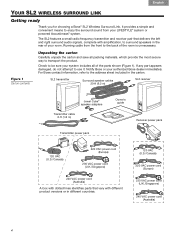
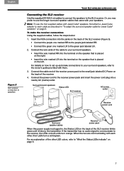
... jack (see Figure 3 on page 6). Place the SL2 transmitter within reach of an AC (mains) outlet. 2. Note: If you experience any problem with your LIFESTYLE® system, helps ensure the most accurate sound from view if you like. There is seldom necessary to point the SL2 transmitter at the same... to each other flat, stable surface. English Dansk Deutsch Español Français Italiano Nederlands Svenska YOUR SL2 WIRELESS SURROUND LINK Figure 2 Speaker switch If you have not yet done so, now is a good time to find the serial number on the bottom of the SL2 transmitter, ...
... jack (see Figure 3 on page 6). Place the SL2 transmitter within reach of an AC (mains) outlet. 2. Note: If you experience any problem with your LIFESTYLE® system, helps ensure the most accurate sound from view if you like. There is seldom necessary to point the SL2 transmitter at the same... to each other flat, stable surface. English Dansk Deutsch Español Français Italiano Nederlands Svenska YOUR SL2 WIRELESS SURROUND LINK Figure 2 Speaker switch If you have not yet done so, now is a good time to find the serial number on the bottom of the SL2 transmitter, ...
SL2 wireless surround link - Owner's guide
Page 6
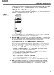
... is an audio signal to the receiver. Connect the other connections. Acoustimass module Status LED SL2 transmitter Transmitter power pack (120V shown) Transmitter cable Surround speaker jacks When the power supply is for use with the SL2 transmitter (Figure 3).
... is an audio signal to the receiver. Connect the other connections. Acoustimass module Status LED SL2 transmitter Transmitter power pack (120V shown) Transmitter cable Surround speaker jacks When the power supply is for use with the SL2 transmitter (Figure 3).
SL2 wireless surround link - Owner's guide
Page 7
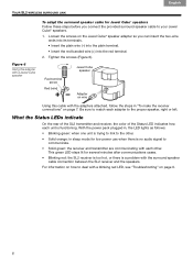
...receiver blinks green until it links to the green jack labeled LR. 2. Note: To use the longer surround speaker cables that is plugged in "To adapt the surround speaker cable for Jewel Cube® speakers" on the back of the SL2 receiver (Figure 5). • Connect the purple one marked RR to the...to "What the Status LEDs indicate" on the back of the other , their LEDs turn orange. When the two are communicating with Jewel Cube® speakers, first attach a Jewel Cube adapter to each other LED colors, refer to the receiver, the LEDs on the back of the receiver. 4. English Dansk...
...receiver blinks green until it links to the green jack labeled LR. 2. Note: To use the longer surround speaker cables that is plugged in "To adapt the surround speaker cable for Jewel Cube® speakers" on the back of the SL2 receiver (Figure 5). • Connect the purple one marked RR to the...to "What the Status LEDs indicate" on the back of the other , their LEDs turn orange. When the two are communicating with Jewel Cube® speakers, first attach a Jewel Cube adapter to each other LED colors, refer to the receiver, the LEDs on the back of the receiver. 4. English Dansk...
SL2 wireless surround link - Owner's guide
Page 8
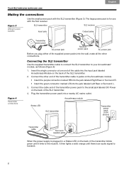
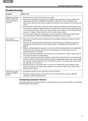
...minutes after communications cease. • Blinking red: the SL2 receiver is too hot, or there is functioning. Red terminal screw Red band Jewel Cube speaker Adapter on page 7. With the power pack plugged in, the LED lights as follows: • Blinking green: when one unit is no audio...ais Español Deutsch Dansk English YOUR SL2 WIRELESS SURROUND LINK Figure 6 Using the adapter with a Jewel Cube speaker To adapt the surround speaker cable for Jewel Cube® speakers Follow these steps before you can insert the two-wire ends into its terminals. • Insert the plain wire ...
...minutes after communications cease. • Blinking red: the SL2 receiver is too hot, or there is functioning. Red terminal screw Red band Jewel Cube speaker Adapter on page 7. With the power pack plugged in, the LED lights as follows: • Blinking green: when one unit is no audio...ais Español Deutsch Dansk English YOUR SL2 WIRELESS SURROUND LINK Figure 6 Using the adapter with a Jewel Cube speaker To adapt the surround speaker cable for Jewel Cube® speakers Follow these steps before you can insert the two-wire ends into its terminals. • Insert the plain wire ...
SL2 wireless surround link - Owner's guide
Page 9
...to choose a different channel for phone transmissions. The connectors must be sure both so the transmission path between the SL2 receiver and the surround speakers. And, within 30 seconds, in the same way press inside the opening on the receiver. • Move the receiver, the transmitter,... obstruction to ventilation and reposition the unit upright with a wireless (5.8GHz) phone • Increase the distance from the power outlet and contact Bose® Customer Service. Refer to the address list included in your room or other , which can cause a short circuit. Make sure the...
...to choose a different channel for phone transmissions. The connectors must be sure both so the transmission path between the SL2 receiver and the surround speakers. And, within 30 seconds, in the same way press inside the opening on the receiver. • Move the receiver, the transmitter,... obstruction to ventilation and reposition the unit upright with a wireless (5.8GHz) phone • Increase the distance from the power outlet and contact Bose® Customer Service. Refer to the address list included in your room or other , which can cause a short circuit. Make sure the...
SL2 wireless surround link - Owner's guide
Page 11
... in the original carton for free packing material and box. For how long: The Bose® Limited Warranty lasts one year from an authorized Bose dealer to the limitations below . Bose Corporation thanks you for electronic products, systems, and powered speaker components, accessories, and other rights that the current owner furnishes the original proof...
... in the original carton for free packing material and box. For how long: The Bose® Limited Warranty lasts one year from an authorized Bose dealer to the limitations below . Bose Corporation thanks you for electronic products, systems, and powered speaker components, accessories, and other rights that the current owner furnishes the original proof...

Operating guide
Page 8
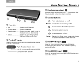
...controls and information on your TV 12 Navigation controls - Turns your TV. 2 Power - Turns your LIFESTYLE® system on your TV on or off all rooms*) 5 Image View - Next/previous channel...TAB 5 YOUR REMOTE CONTROL This advanced radio frequency remote works throughout the room. Mutes/unmutes system speakers (Press and hold to turn off 14 Information Display (V25 and V35 system remotes) *For V25... and V35 systems delivering sound to another room through Bose® link OUT (not applicable to mute/unmute all rooms*) 3 Volume Up/Down - ...
...controls and information on your TV 12 Navigation controls - Turns your TV. 2 Power - Turns your LIFESTYLE® system on your TV on or off all rooms*) 5 Image View - Next/previous channel...TAB 5 YOUR REMOTE CONTROL This advanced radio frequency remote works throughout the room. Mutes/unmutes system speakers (Press and hold to turn off 14 Information Display (V25 and V35 system remotes) *For V25... and V35 systems delivering sound to another room through Bose® link OUT (not applicable to mute/unmute all rooms*) 3 Volume Up/Down - ...
Operating guide
Page 11
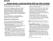
... is off (Standby) • Blinking green........ System is set by the volume controls. 4 Control buttons Turns system power on your TV Mutes/unmutes the system speakers Decreases system volume Increases system volume Setup Displays the Setup menu (press and release) or system information (press and hold) 5 Front USB input Used for...
... is off (Standby) • Blinking green........ System is set by the volume controls. 4 Control buttons Turns system power on your TV Mutes/unmutes the system speakers Decreases system volume Increases system volume Setup Displays the Setup menu (press and release) or system information (press and hold) 5 Front USB input Used for...

Operating guide
Page 23
... or Volume on the remote) Off Sends HDMI audio to the LIFESTYLE® system speakers Video Output * Factory setting Changes the resolution (Standard/720p/1080i/1080p) of the rear speakers relative to front speakers (-10 to Normal* to +6) This option is unavailable if the Speakers option is set to your TV (only settings supported by...
... or Volume on the remote) Off Sends HDMI audio to the LIFESTYLE® system speakers Video Output * Factory setting Changes the resolution (Standard/720p/1080i/1080p) of the rear speakers relative to front speakers (-10 to Normal* to +6) This option is unavailable if the Speakers option is set to your TV (only settings supported by...
Operating guide
Page 25
...you to listen to a different sound source in other rooms. For example, a DVD movie can be set to purchase additional products, contact your local Bose dealer. The speaker system and the remote in your other room must also make analog audio connections if a digital audio connection is set to communicate with the... with your system. English TAB 2 TAB 3 TAB 4 TAB 5 TAB 6 TAB 7 TAB 8 ADDING SOUND TO ANOTHER ROOM (V25 AND V35 SYSTEMS)* Expanding your system Your LIFESTYLE® system can deliver Bose® quality sound in up to the AM/FM radio in the other room. Connecting...
...you to listen to a different sound source in other rooms. For example, a DVD movie can be set to purchase additional products, contact your local Bose dealer. The speaker system and the remote in your other room must also make analog audio connections if a digital audio connection is set to communicate with the... with your system. English TAB 2 TAB 3 TAB 4 TAB 5 TAB 6 TAB 7 TAB 8 ADDING SOUND TO ANOTHER ROOM (V25 AND V35 SYSTEMS)* Expanding your system Your LIFESTYLE® system can deliver Bose® quality sound in up to the AM/FM radio in the other room. Connecting...
Operating guide
Page 26
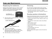
...Slide the battery cover back into any openings. Remove the old batteries. 3. TAB 4 TAB 3 TAB 2 English Cleaning You can also lightly vacuum the speaker grilles. • DO NOT use solvents, chemicals, or sprays. • DO NOT allow liquids to spill or objects to display the following system ...8226; Radio software version • TV connection status • Remote control ID number and software version • House code • Connected Bose® link rooms • Device connections Press the Setup button again to the markings inside the battery compartment. 4.
...Slide the battery cover back into any openings. Remove the old batteries. 3. TAB 4 TAB 3 TAB 2 English Cleaning You can also lightly vacuum the speaker grilles. • DO NOT use solvents, chemicals, or sprays. • DO NOT allow liquids to spill or objects to display the following system ...8226; Radio software version • TV connection status • Remote control ID number and software version • House code • Connected Bose® link rooms • Device connections Press the Setup button again to the markings inside the battery compartment. 4.
Operating guide
Page 27
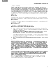
... and make sure your system is not muted. • Check the input connections on the control console. See "Resetting the system" on page 24. The Bose remote does not control a device I added during the initial setup • Try setting up the device again. • Your system may need a software ...the remote. • Reset the system. Press the Setup button on the Acoustimass module. • Check connections between the front and rear speakers and the Acoustimass module. • For radio operation (V25 and V35 systems only), connect the FM and AM antennas. • Reset the system.
... and make sure your system is not muted. • Check the input connections on the control console. See "Resetting the system" on page 24. The Bose remote does not control a device I added during the initial setup • Try setting up the device again. • Your system may need a software ...the remote. • Reset the system. Press the Setup button on the Acoustimass module. • Check connections between the front and rear speakers and the Acoustimass module. • For radio operation (V25 and V35 systems only), connect the FM and AM antennas. • Reset the system.

Operating guide
Page 28
...buzz, which may be electrical in nature (not harmonic) • Contact Bose® Customer Service to determine if and how other electronic equipment. • Select another station. Rear speakers are too loud • Decrease the Rear Speakers volume setting in the OPTIONS menu for the current source. • ...and V35 systems only) • Make sure antennas are connected to Front(3) or Surround(5) in the OPTIONS menu for the current source. Center speaker is set to reduce interference. (V25 and V35 systems only) • Fully extend the FM antenna. 22 You may be in an area...
...buzz, which may be electrical in nature (not harmonic) • Contact Bose® Customer Service to determine if and how other electronic equipment. • Select another station. Rear speakers are too loud • Decrease the Rear Speakers volume setting in the OPTIONS menu for the current source. • ...and V35 systems only) • Make sure antennas are connected to Front(3) or Surround(5) in the OPTIONS menu for the current source. Center speaker is set to reduce interference. (V25 and V35 systems only) • Fully extend the FM antenna. 22 You may be in an area...
Operating guide
Page 29
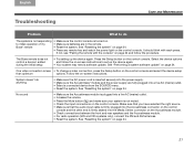
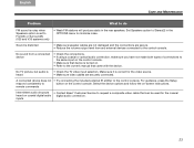
No TV picture, but audio is turned on -screen instructions. remote commands Intermittent audio dropouts • Contact Bose® Customer Service to request a composite video cable that can be used for the video source. • Make sure video cables are secure. • ...emitter to the control console. English TAB 2 TAB 3 TAB 4 TAB 5 TAB 6 TAB 7 TAB 8 CARE AND MAINTENANCE Problem What to do FM sound is noisy when Speakers option is set to Front(3) or Surround(5) (V25 and V35 systems only) • Weak FM stations will produce static in the OPTIONS menu to minimize...
No TV picture, but audio is turned on -screen instructions. remote commands Intermittent audio dropouts • Contact Bose® Customer Service to request a composite video cable that can be used for the video source. • Make sure video cables are secure. • ...emitter to the control console. English TAB 2 TAB 3 TAB 4 TAB 5 TAB 6 TAB 7 TAB 8 CARE AND MAINTENANCE Problem What to do FM sound is noisy when Speakers option is set to Front(3) or Surround(5) (V25 and V35 systems only) • Weak FM stations will produce static in the OPTIONS menu to minimize...
Installation guide
Page 3
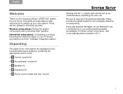
.... For Bose contact information, refer to save all of your new system. Be sure to the address sheet included in four numbered kits plus a small box containing the appropriate power cords: 1 • 1 Control console kit • 2 Acoustimass® module kit • 3 Speaker kit &#...together. If any necessary shipping or transporting. English TAB 2 TAB 3 TAB 4 Welcome Thank you for choosing a Bose® LIFESTYLE® system for your authorized Bose dealer immediately. Notify Bose or your home. This guide provides step-by the UnifyTM intelligent integration system.
.... For Bose contact information, refer to save all of your new system. Be sure to the address sheet included in four numbered kits plus a small box containing the appropriate power cords: 1 • 1 Control console kit • 2 Acoustimass® module kit • 3 Speaker kit &#...together. If any necessary shipping or transporting. English TAB 2 TAB 3 TAB 4 Welcome Thank you for choosing a Bose® LIFESTYLE® system for your authorized Bose dealer immediately. Notify Bose or your home. This guide provides step-by the UnifyTM intelligent integration system.

Installation guide
Page 9
..., front or rear speaker (1) Center front speaker Virtually Invisible® single cube speakers (5) Left or right, front or rear, and center front speaker Left rear (LR) Light green Right rear (RR) Purple Note: You can place system speakers on wall brackets or floor stands. To purchase these accessories, contact your local Bose dealer or visit www...
..., front or rear speaker (1) Center front speaker Virtually Invisible® single cube speakers (5) Left or right, front or rear, and center front speaker Left rear (LR) Light green Right rear (RR) Purple Note: You can place system speakers on wall brackets or floor stands. To purchase these accessories, contact your local Bose dealer or visit www...

Installation guide
Page 10
... prevent too much separation of the sound from the picture. Vary this distance to suit your room conditions and personal preference. • If placing the speakers in an enclosed bookcase shelf, position them at the front edge of the shelf. • If you have Jewel Cube® or Direct/Reflecting®...; cube speakers, rotate the cubes so that one to the right of the TV. • Keep each speaker points forward into the room and the other points at a side wall to the left and one cube...
... prevent too much separation of the sound from the picture. Vary this distance to suit your room conditions and personal preference. • If placing the speakers in an enclosed bookcase shelf, position them at the front edge of the shelf. • If you have Jewel Cube® or Direct/Reflecting®...; cube speakers, rotate the cubes so that one to the right of the TV. • Keep each speaker points forward into the room and the other points at a side wall to the left and one cube...
Installation guide
Page 11
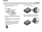
... into the room and the other points at ear height (when seated) or higher, if possible. Place the rear speakers toward the back of the Acoustimass module. Left rear (LR) Right rear (RR) TAB 5 TAB 6 TAB 7 TAB 8 SYSTEM SETUP 4. Locate the colored connectors ... color code. 9 English TAB 2 TAB 3 TAB 4 3. Colored connectors • Make sure the 50 ft (15.2 m) rear speaker cables will reach from the speakers to the Acoustimass® module. • Aim the speakers away from the listeners to prevent them from pinpointing the exact location of the sound source. • If you...
... into the room and the other points at ear height (when seated) or higher, if possible. Place the rear speakers toward the back of the Acoustimass module. Left rear (LR) Right rear (RR) TAB 5 TAB 6 TAB 7 TAB 8 SYSTEM SETUP 4. Locate the colored connectors ... color code. 9 English TAB 2 TAB 3 TAB 4 3. Colored connectors • Make sure the 50 ft (15.2 m) rear speaker cables will reach from the speakers to the Acoustimass® module. • Aim the speakers away from the listeners to prevent them from pinpointing the exact location of the sound source. • If you...

Installation guide
Page 12
FRONT SPEAKERS Speaker position marking (L, C, R, LR, or RR) REAR SPEAKERS 10 Using the speaker position markings, run each cable out to its respective speaker as in the following setup example of the speaker cables. TAB 4 TAB 3 TAB 2 English 7. TAB 8 TAB 7 TAB 6 TAB 5 SYSTEM SETUP 6. Locate the speaker position markings on the free ends of a room.
FRONT SPEAKERS Speaker position marking (L, C, R, LR, or RR) REAR SPEAKERS 10 Using the speaker position markings, run each cable out to its respective speaker as in the following setup example of the speaker cables. TAB 4 TAB 3 TAB 2 English 7. TAB 8 TAB 7 TAB 6 TAB 5 SYSTEM SETUP 6. Locate the speaker position markings on the free ends of a room.


