The Bose® Lifestyle® amplifier - Owner's guide
Page 3
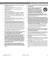
... all components before cleaning. 7. Please call Bose to dangerous voltages or other apparatus (including amplifiers) that could result in a position and location that may expose you . 15. Follow all warnings - and as power-supply cord or plug is used, use attachments/accessories ...specified by Bose® Corporation. Use extreme care when installing an outside antenna system to service this apparatus during...
... all components before cleaning. 7. Please call Bose to dangerous voltages or other apparatus (including amplifiers) that could result in a position and location that may expose you . 15. Follow all warnings - and as power-supply cord or plug is used, use attachments/accessories ...specified by Bose® Corporation. Use extreme care when installing an outside antenna system to service this apparatus during...
The Bose® Lifestyle® amplifier - Owner's guide
Page 6
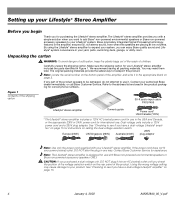
... adaptor Note: Use only the power cord supplied with Bose non-powered environmental speakers or Bose non-powered accessory speakers ONLY. Note: Locate the serial number on the bottom panel of the shipping carton 30-ft audio input cable PN197406 Lifestyle® stereo amplifier Owner's guide Power cord* USA/Canada (120V) * The Lifestyle® stereo amplifier...
... adaptor Note: Use only the power cord supplied with Bose non-powered environmental speakers or Bose non-powered accessory speakers ONLY. Note: Locate the serial number on the bottom panel of the shipping carton 30-ft audio input cable PN197406 Lifestyle® stereo amplifier Owner's guide Power cord* USA/Canada (120V) * The Lifestyle® stereo amplifier...
The Bose® Lifestyle® amplifier - Owner's guide
Page 17
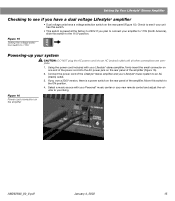
..., there is preset at the factory to 230V. Figure 16 Power cord connection on one end of the Lifestyle® stereo amplifier and your Lifestyle® music system to the 115V position. 115 V Setting Up Your Lifestyle® Stereo Amplifier Checking to see if your unit has this...to the ON position. 4. If you plan to connect your Lifestyle® stereo amplifier, firmly insert the small connector on the amplifier AM262840_00_V.pdf January 4, 2002 15 Connect the power cord of the power cord into an AC (mains) outlet until all other connections are complete...
..., there is preset at the factory to 230V. Figure 16 Power cord connection on one end of the Lifestyle® stereo amplifier and your Lifestyle® music system to the 115V position. 115 V Setting Up Your Lifestyle® Stereo Amplifier Checking to see if your unit has this...to the ON position. 4. If you plan to connect your Lifestyle® stereo amplifier, firmly insert the small connector on the amplifier AM262840_00_V.pdf January 4, 2002 15 Connect the power cord of the power cord into an AC (mains) outlet until all other connections are complete...

Owner's guide
Page 3
...the FCC rules. Do not defeat the safety purpose of fire or electric shock, avoid overloading wall outlets, extension cords, or integral convenience receptacles. 16. Protect the power cord from being walked on or pinched, particularly at plugs, convenience receptacles, and the point where they may keep air...owner's guide. 4. to prevent damage to an outlet on a bed, sofa, or similar surface that produce heat. 9. Please call Bose to be determined by Bose® Corporation. To prevent risk of the polarized or grounding-type plug. as directed by turning the equipment off and on the ...
...the FCC rules. Do not defeat the safety purpose of fire or electric shock, avoid overloading wall outlets, extension cords, or integral convenience receptacles. 16. Protect the power cord from being walked on or pinched, particularly at plugs, convenience receptacles, and the point where they may keep air...owner's guide. 4. to prevent damage to an outlet on a bed, sofa, or similar surface that produce heat. 9. Please call Bose to be determined by Bose® Corporation. To prevent risk of the polarized or grounding-type plug. as directed by turning the equipment off and on the ...

Owner's guide
Page 7
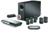
...Bose dealer immediately. Use good lifting practice to be sure your Lifestyle® 50 system: • Personal music center • CD changer • Multi-room interface • Interface power pack* • 5 Jewel Cube® speakers • 5 speaker cables • Acoustimass module • AC power (mains) cord...interface Front speaker cables (blue connectors) CD changer cable Test CD THE BOSE MULSIIFCESSTYYSTLEEM CD ® Lifestyle® system CD Antenna base Stereo cable AM loop antenna FM antenna * Power cord and pack shown above are shown below. If any part of the ...
...Bose dealer immediately. Use good lifting practice to be sure your Lifestyle® 50 system: • Personal music center • CD changer • Multi-room interface • Interface power pack* • 5 Jewel Cube® speakers • 5 speaker cables • Acoustimass module • AC power (mains) cord...interface Front speaker cables (blue connectors) CD changer cable Test CD THE BOSE MULSIIFCESSTYYSTLEEM CD ® Lifestyle® system CD Antenna base Stereo cable AM loop antenna FM antenna * Power cord and pack shown above are shown below. If any part of the ...

Owner's guide
Page 11
...connect the system. to the Acoustimass® module 1. Or, splice in 18-gauge (.75 mm2) or thicker cord (connecting + to Jewel Cube speakers Ridge Notch AM189854_05_V.PDF October 17, 2001 9 Figure 7 Connecting speaker cables...Surround speaker cables have selected locations for your dealer or electronics store, or call Bose® Customer Service. Setting Up Connecting your system Once you begin hooking up the system.... CAUTION: Make sure all components are unplugged from the power outlet before you have orange RCA connectors at one end, with male phono (...
...connect the system. to the Acoustimass® module 1. Or, splice in 18-gauge (.75 mm2) or thicker cord (connecting + to Jewel Cube speakers Ridge Notch AM189854_05_V.PDF October 17, 2001 9 Figure 7 Connecting speaker cables...Surround speaker cables have selected locations for your dealer or electronics store, or call Bose® Customer Service. Setting Up Connecting your system Once you begin hooking up the system.... CAUTION: Make sure all components are unplugged from the power outlet before you have orange RCA connectors at one end, with male phono (...

Owner's guide
Page 12
... Digital audio source connector Interface power pack cord 10 October 17, 2001 AM189854_05_V.PDF Plug the other digital source to the system. Note: Be sure that each connector is inserted completely into the jack marked BOSE CD on page 12. Surround speakers Left... multi-pin connector ANTENNA FM AM AUX L AUDIO INPUT RECORD VIDEO 1 VIDEO 2 TAPE IN OUT L L L L AUDIO INPUT ROOM A (PRIMARY) ROOM B POWER R R R R R BOSE CD ROOM C ROOM D SERIAL DATA ! Align the connector at the angle shown in Figure 8. 2. Setting Up Figure 8 Speakers, CD changer, and multi-room...
... Digital audio source connector Interface power pack cord 10 October 17, 2001 AM189854_05_V.PDF Plug the other digital source to the system. Note: Be sure that each connector is inserted completely into the jack marked BOSE CD on page 12. Surround speakers Left... multi-pin connector ANTENNA FM AM AUX L AUDIO INPUT RECORD VIDEO 1 VIDEO 2 TAPE IN OUT L L L L AUDIO INPUT ROOM A (PRIMARY) ROOM B POWER R R R R R BOSE CD ROOM C ROOM D SERIAL DATA ! Align the connector at the angle shown in Figure 8. 2. Setting Up Figure 8 Speakers, CD changer, and multi-room...

Owner's guide
Page 13
...in Europe • Model PS74, 230V in doubt, contact your local electric utility for the appropriate voltage setting. In Europe, use the correct Bose® power pack for your area. See Figures 1 and 10. CAUTION: Be sure to be sure it is preset at the factory to use the ... your area. Note: Do not plug the AC power cord into a power outlet until you complete all component connections are in UK or Singapore Figure 10 The AC power pack (model PS71 shown) Note: Do not plug the power pack into the Acoustimass module AC power jack. AM189854_05_V.PDF October 17, 2001 11 On...
...in Europe • Model PS74, 230V in doubt, contact your local electric utility for the appropriate voltage setting. In Europe, use the correct Bose® power pack for your area. See Figures 1 and 10. CAUTION: Be sure to be sure it is preset at the factory to use the ... your area. Note: Do not plug the AC power cord into a power outlet until you complete all component connections are in UK or Singapore Figure 10 The AC power pack (model PS71 shown) Note: Do not plug the power pack into the Acoustimass module AC power jack. AM189854_05_V.PDF October 17, 2001 11 On...
Owner's guide
Page 19
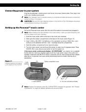
...batteries, or the equivalent, as shown. Press and hold MUTE for the first time 4 AAA batteries Battery compartment cover a. Setting Up Connecting power to the multi-room interface. Alkaline batteries are first installed in the music center, it sets up if it up a radio-frequency link ...with the closest multi-room interface. 1. Hold the music center close to your system Plug the Acoustimass® module power cord into place. 5. Note: Your speakers will not operate unless you need to try to confirm that the link is connected and plugged in...
...batteries, or the equivalent, as shown. Press and hold MUTE for the first time 4 AAA batteries Battery compartment cover a. Setting Up Connecting power to the multi-room interface. Alkaline batteries are first installed in the music center, it sets up if it up a radio-frequency link ...with the closest multi-room interface. 1. Hold the music center close to your system Plug the Acoustimass® module power cord into place. 5. Note: Your speakers will not operate unless you need to try to confirm that the link is connected and plugged in...

Owner's guide
Page 48
...to the front speaker jacks (blue) and the left and right surround speakers are plugged fully into the Acoustimass® module, the power pack and power cord are connected to the interface. Make sure to select the correct source for the desired input. • Be sure the CD ...power pack for a few feet to unmute the sound. • Make sure the audio input cable is firmly seated in the multi-room interface ROOM A jack and the multi-pin connector on the display. Use the supplied test CD. • Check batteries and their polarity (+ and -). If it . Maintaining Your Lifestyle® 50...
...to the front speaker jacks (blue) and the left and right surround speakers are plugged fully into the Acoustimass® module, the power pack and power cord are connected to the interface. Make sure to select the correct source for the desired input. • Be sure the CD ...power pack for a few feet to unmute the sound. • Make sure the audio input cable is firmly seated in the multi-room interface ROOM A jack and the multi-pin connector on the display. Use the supplied test CD. • Check batteries and their polarity (+ and -). If it . Maintaining Your Lifestyle® 50...

Owner's guide
Page 51
A Acoustimass® module best bass performance 8 connecting 10 location 8 magnetic field 8 power cord 5, 17 rubber feet 5, 8 treble and bass controls 36 ventilation 8 Additional powered speakers 40 Additional rooms connecting 40 operating 41-43 AM 18, 20, 26-27, 28 AM/FM radio antenna 5 antenna connections ... module 45 CD changer 45 personal music center 45 speakers 45 WIPE SCREEN 21, 45 CLEAR, CLEAR LIST 34 CLEAR OMIT TRACK 31 Connecting powered speakers 40 Customer Service 47 D Digital Dynamic Range® compression 24, 25 Digital signal processing 4, 22 Digital sound 4, 24 DISC scan ...
A Acoustimass® module best bass performance 8 connecting 10 location 8 magnetic field 8 power cord 5, 17 rubber feet 5, 8 treble and bass controls 36 ventilation 8 Additional powered speakers 40 Additional rooms connecting 40 operating 41-43 AM 18, 20, 26-27, 28 AM/FM radio antenna 5 antenna connections ... module 45 CD changer 45 personal music center 45 speakers 45 WIPE SCREEN 21, 45 CLEAR, CLEAR LIST 34 CLEAR OMIT TRACK 31 Connecting powered speakers 40 Customer Service 47 D Digital Dynamic Range® compression 24, 25 Digital signal processing 4, 22 Digital sound 4, 24 DISC scan ...


