The Bose® Lifestyle® amplifier - Owner's guide
Page 6
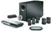
... danger of suffocation, keep the plastic bags out of the reach of the shipping carton 30-ft audio input cable PN197406 Lifestyle® stereo amplifier Owner's guide Power cord* USA/Canada (120V) * The Lifestyle® stereo amplifier includes a 120V AC (mains) power cord for use in the ... product. CAUTION: If you purchased a dual voltage unit, DO NOT plug it into an AC (mains) outlet until you can enjoy Bose quality sound and Lifestyle® system convenience in the amplifier, ensures full, rich stereo sound, even when the speakers are playing at low volumes. ...
... danger of suffocation, keep the plastic bags out of the reach of the shipping carton 30-ft audio input cable PN197406 Lifestyle® stereo amplifier Owner's guide Power cord* USA/Canada (120V) * The Lifestyle® stereo amplifier includes a 120V AC (mains) power cord for use in the ... product. CAUTION: If you purchased a dual voltage unit, DO NOT plug it into an AC (mains) outlet until you can enjoy Bose quality sound and Lifestyle® system convenience in the amplifier, ensures full, rich stereo sound, even when the speakers are playing at low volumes. ...
The Bose® Lifestyle® amplifier - Owner's guide
Page 7
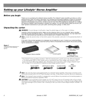
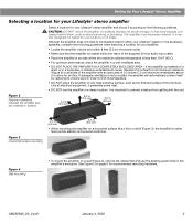
...close to either your amplifier: • Locate the amplifier indoors and within the reach of the supplied 30-foot audio input cable. • Place the amplifier in the amplifier's enclosure. Although the amplifier does not need to be ...ambient temperature is important to prevent moisture from getting into the unit. Setting Up Your Lifestyle® Stereo Amplifier Selecting a location for your Lifestyle® stereo amplifier Select a location for your Lifestyle® stereo amplifier and mount it according to the following guidelines when ...
...close to either your amplifier: • Locate the amplifier indoors and within the reach of the supplied 30-foot audio input cable. • Place the amplifier in the amplifier's enclosure. Although the amplifier does not need to be ...ambient temperature is important to prevent moisture from getting into the unit. Setting Up Your Lifestyle® Stereo Amplifier Selecting a location for your Lifestyle® stereo amplifier Select a location for your Lifestyle® stereo amplifier and mount it according to the following guidelines when ...
The Bose® Lifestyle® amplifier - Owner's guide
Page 9
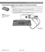
Insert the single multi-pin connector at one end of the audio input cable into one of the unused ROOM output jacks (B, C, or D) on the rear panel of the amplifier. Setting Up Your Lifestyle® Stereo Amplifier Connecting the Lifestyle® stereo amplifier to a multi-room interface CAUTION: Before making any connections...
Insert the single multi-pin connector at one end of the audio input cable into one of the unused ROOM output jacks (B, C, or D) on the rear panel of the amplifier. Setting Up Your Lifestyle® Stereo Amplifier Connecting the Lifestyle® stereo amplifier to a multi-room interface CAUTION: Before making any connections...
The Bose® Lifestyle® amplifier - Owner's guide
Page 11
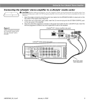
Figure 8 Cable connections between the Lifestyle® media center and the Lifestyle® stereo amplifier Lifestyle® SA-1 stereo amplifier rear panel Lifestyle® media center rear panel 30-ft audio input cable (supplied) AM262840_00_V.pdf January 4, 2002 9 DO NOT plug the amplifier into the R (right) INPUT jack of the audio input cable, insert the 3.5 mm mini-plug into...
Figure 8 Cable connections between the Lifestyle® media center and the Lifestyle® stereo amplifier Lifestyle® SA-1 stereo amplifier rear panel Lifestyle® media center rear panel 30-ft audio input cable (supplied) AM262840_00_V.pdf January 4, 2002 9 DO NOT plug the amplifier into the R (right) INPUT jack of the audio input cable, insert the 3.5 mm mini-plug into...
The Bose® Lifestyle® amplifier - Owner's guide
Page 13
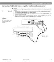
... of the amplifier. Insert the red RCA piggyback connector into the L (left) INPUT jack. SPEAKER OUTPUTS INPUT Model 20 music center rear panel 30-ft audio input cable (supplied) AM262840_00_V.pdf January 4, 2002 11 DO NOT plug the amplifier into an outlet until you...(Figure 10). 2. At the other connections. 1. Insert the single multi-pin connector at one end of the audio input cable into the SYSTEM CONTROL jack on the rear panel of the amplifier. 3. Lifestyle® stereo amplifier rear panel 4 Ω MINIMUM LL R L SYSTEM RR CONTROL L R +-...
... of the amplifier. Insert the red RCA piggyback connector into the L (left) INPUT jack. SPEAKER OUTPUTS INPUT Model 20 music center rear panel 30-ft audio input cable (supplied) AM262840_00_V.pdf January 4, 2002 11 DO NOT plug the amplifier into an outlet until you...(Figure 10). 2. At the other connections. 1. Insert the single multi-pin connector at one end of the audio input cable into the SYSTEM CONTROL jack on the rear panel of the amplifier. 3. Lifestyle® stereo amplifier rear panel 4 Ω MINIMUM LL R L SYSTEM RR CONTROL L R +-...
The Bose® Lifestyle® amplifier - Owner's guide
Page 15
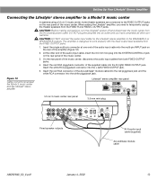
...; amplifier, you have completed all other end of the music center. CAUTION: DO NOT connect the audio input cable for the Lifestyle® stereo amplifier to temporarily unplug the theater speakers from the FIXED R and FIXED L OUTPUT jacks. The amplifi...er is designed to the FIXED OUTPUT jacks on the rear panel of the audio input cable, insert the 3.5 mm mini-plug into the L (left) FIXED OUTPUT jack. 5. Setting Up Your Lifestyle® Stereo Amplifier Connecting the Lifestyle® stereo amplifier to a Model 5 music center In systems using a...
...; amplifier, you have completed all other end of the music center. CAUTION: DO NOT connect the audio input cable for the Lifestyle® stereo amplifier to temporarily unplug the theater speakers from the FIXED R and FIXED L OUTPUT jacks. The amplifi...er is designed to the FIXED OUTPUT jacks on the rear panel of the audio input cable, insert the 3.5 mm mini-plug into the L (left) FIXED OUTPUT jack. 5. Setting Up Your Lifestyle® Stereo Amplifier Connecting the Lifestyle® stereo amplifier to a Model 5 music center In systems using a...

The Bose® Lifestyle® amplifier - Owner's guide
Page 18
...Lifestyle® stereo amplifier" on the audio input cable.) • Disconnect any sprays near the amplifier. Do not use caulking, apply it only after installing the Lifestyle® stereo amplifier, follow the guidelines below. Refer to arrange for service, or contact Bose...Model 20 music center, make sure the audio input cable is inserted into SPEAKER ZONE 2. • If using a Model 5 music center for home theater (Lifestyle® 12 or Lifestyle® 8 systems), make sure the amplifier audio input cable is plugged into any solvents, chemicals, or...
...Lifestyle® stereo amplifier" on the audio input cable.) • Disconnect any sprays near the amplifier. Do not use caulking, apply it only after installing the Lifestyle® stereo amplifier, follow the guidelines below. Refer to arrange for service, or contact Bose...Model 20 music center, make sure the audio input cable is inserted into SPEAKER ZONE 2. • If using a Model 5 music center for home theater (Lifestyle® 12 or Lifestyle® 8 systems), make sure the amplifier audio input cable is plugged into any solvents, chemicals, or...

Owner's guide
Page 7
... CD changer have been removed before setting up the system. Check to use . Then write them on your Lifestyle® 50 system contains the parts identified in the spaces provided on the bottom of the product appears damaged, do not ... cord Interface power pack Audio input cable 6 5 4 3 2 1 6 DISK MAGAZINE CD magazine Rubber feet (5 pairs) Surround speaker cables (orange connectors) Multi-room interface Front speaker cables (blue connectors) CD changer cable Test CD THE BOSE MULSIIFCESSTYYSTLEEM CD ® Lifestyle® system CD Antenna base Stereo cable AM loop antenna FM ...
... CD changer have been removed before setting up the system. Check to use . Then write them on your Lifestyle® 50 system contains the parts identified in the spaces provided on the bottom of the product appears damaged, do not ... cord Interface power pack Audio input cable 6 5 4 3 2 1 6 DISK MAGAZINE CD magazine Rubber feet (5 pairs) Surround speaker cables (orange connectors) Multi-room interface Front speaker cables (blue connectors) CD changer cable Test CD THE BOSE MULSIIFCESSTYYSTLEEM CD ® Lifestyle® system CD Antenna base Stereo cable AM loop antenna FM ...

Owner's guide
Page 10
Select a convenient location - Place the Acoustimass module within 30 feet (9.1 m) of the Acoustimass module (the length of the audio input cable). 2. Do not place the module on the end provide ventilation for the module, place the four self-adhesive rubber feet near the ... enough to the multi-room interface to your dealer or call Bose® Customer Service. CAUTION: The magnetic field from scratches. 6. Place the multi-room interface within reach of sight if you should not be placed out of the audio input cable, speaker cables, and an AC power (mains) outlet. 4. Setting Up ...
Select a convenient location - Place the Acoustimass module within 30 feet (9.1 m) of the Acoustimass module (the length of the audio input cable). 2. Do not place the module on the end provide ventilation for the module, place the four self-adhesive rubber feet near the ... enough to the multi-room interface to your dealer or call Bose® Customer Service. CAUTION: The magnetic field from scratches. 6. Place the multi-room interface within reach of sight if you should not be placed out of the audio input cable, speaker cables, and an AC power (mains) outlet. 4. Setting Up ...

Owner's guide
Page 12
... interface with the audio input cable (Figure 8). 1. Surround speakers Left Right Front speakers Right Center Left AUDIO INPUT Right-angle connector L R R AUDIO INPUT SURROUND RIGHT FRONT RIGHT LEFT CENTER LEFT OUTPUTS TO CUBE SPEAKERS C L CD changer cable ROOM A multi-pin connector ANTENNA FM AM AUX L AUDIO INPUT RECORD VIDEO 1 VIDEO 2 TAPE IN OUT L L L L AUDIO INPUT ROOM A (PRIMARY) ROOM B POWER R R R R R BOSE CD ROOM C ROOM...
... interface with the audio input cable (Figure 8). 1. Surround speakers Left Right Front speakers Right Center Left AUDIO INPUT Right-angle connector L R R AUDIO INPUT SURROUND RIGHT FRONT RIGHT LEFT CENTER LEFT OUTPUTS TO CUBE SPEAKERS C L CD changer cable ROOM A multi-pin connector ANTENNA FM AM AUX L AUDIO INPUT RECORD VIDEO 1 VIDEO 2 TAPE IN OUT L L L L AUDIO INPUT ROOM A (PRIMARY) ROOM B POWER R R R R R BOSE CD ROOM C ROOM...

Owner's guide
Page 14
... digital audio source has an optical connector, you excellent home theater sound. Cables may be supplied with an RCA (coaxial) connector. Connect the DVD player's analog output to the multi-room interface inputs. Consult your dealer or contact Bose®. Note: Your Lifestyle® 50 system ...includes one 6-foot (1.8 m) stereo cable to connect the right (R) and left (L) jacks. 12 October 17, 2001 AM189854_05_V....
... digital audio source has an optical connector, you excellent home theater sound. Cables may be supplied with an RCA (coaxial) connector. Connect the DVD player's analog output to the multi-room interface inputs. Consult your dealer or contact Bose®. Note: Your Lifestyle® 50 system ...includes one 6-foot (1.8 m) stereo cable to connect the right (R) and left (L) jacks. 12 October 17, 2001 AM189854_05_V....

Owner's guide
Page 15
... Lifestyle® 50 system Cable TV DVD player VCR Digital audio output L R V Multi-room interface L R V ANTENNA FM AM AUX L AUDIO INPUT RECORD VIDEO 1 VIDEO 2 TAPE IN OUT L L L L AUDIO INPUT ROOM A (PRIMARY) ROOM B POWER R R R R R BOSE CD ROOM C ROOM D SERIAL DATA ! In each example, the analog outputs from your TV: • Connect the TV fixed audio outputs to the VIDEO 2 inputs on the audio input cable...
... Lifestyle® 50 system Cable TV DVD player VCR Digital audio output L R V Multi-room interface L R V ANTENNA FM AM AUX L AUDIO INPUT RECORD VIDEO 1 VIDEO 2 TAPE IN OUT L L L L AUDIO INPUT ROOM A (PRIMARY) ROOM B POWER R R R R R BOSE CD ROOM C ROOM D SERIAL DATA ! In each example, the analog outputs from your TV: • Connect the TV fixed audio outputs to the VIDEO 2 inputs on the audio input cable...

Owner's guide
Page 16
... the volume control up - Figure 13 Alternate home theater connections to the Lifestyle® 50 system Cable TV LR DVD player VCR V TV L R V Digital audio output L R Multi-room interface ANTENNA FM AM AUX L AUDIO INPUT RECORD VIDEO 1 VIDEO 2 TAPE IN OUT L L L L AUDIO INPUT ROOM A (PRIMARY) ROOM B POWER R R R R R BOSE CD ROOM C ROOM D SERIAL DATA ! Do not connect any special TV...
... the volume control up - Figure 13 Alternate home theater connections to the Lifestyle® 50 system Cable TV LR DVD player VCR V TV L R V Digital audio output L R Multi-room interface ANTENNA FM AM AUX L AUDIO INPUT RECORD VIDEO 1 VIDEO 2 TAPE IN OUT L L L L AUDIO INPUT ROOM A (PRIMARY) ROOM B POWER R R R R R BOSE CD ROOM C ROOM D SERIAL DATA ! Do not connect any special TV...

Owner's guide
Page 17
... other external components Use standard RCA audio cables to connect other device VCR, TV, or laserdisc VCR, TV, or laserdisc Outputs Inputs Tape deck AM189854_05_V.PDF October 17, 2001 15 See Figure 14. Note: The Lifestyle® 50 system cannot turn on the multi-...14 Connecting external components ANTENNA FM AM AUX L AUDIO INPUT RECORD VIDEO 1 VIDEO 2 TAPE IN OUT L L L L AUDIO OUTPUT ROOM A (PRIMARY) ROOM B POWER R R R R R BOSE CD ROOM C ROOM D SERIAL DATA ! Note: There is the display for a digital source) input jacks, matching the red plug to R (...
... other external components Use standard RCA audio cables to connect other device VCR, TV, or laserdisc VCR, TV, or laserdisc Outputs Inputs Tape deck AM189854_05_V.PDF October 17, 2001 15 See Figure 14. Note: The Lifestyle® 50 system cannot turn on the multi-...14 Connecting external components ANTENNA FM AM AUX L AUDIO INPUT RECORD VIDEO 1 VIDEO 2 TAPE IN OUT L L L L AUDIO OUTPUT ROOM A (PRIMARY) ROOM B POWER R R R R R BOSE CD ROOM C ROOM D SERIAL DATA ! Note: There is the display for a digital source) input jacks, matching the red plug to R (...

Owner's guide
Page 42
...your plan for connecting the cable to the selected ROOM jack on the multi-room interface Room A, B, C, and D jacks 40 October 17, 2001 AM189854_05_V.pdf Operating a Multi-Room Lifestyle® 50 System Connecting additional rooms Follow the placement guidelines for the Bose® powered speakers that ... jacks on the back of this owner's guide. Connect the audio input cable from the power outlet before you plan to connect. Then review your speakers for how to connect these speakers to complete the connections, call Bose Customer Service at the numbers listed on the back of the...
...your plan for connecting the cable to the selected ROOM jack on the multi-room interface Room A, B, C, and D jacks 40 October 17, 2001 AM189854_05_V.pdf Operating a Multi-Room Lifestyle® 50 System Connecting additional rooms Follow the placement guidelines for the Bose® powered speakers that ... jacks on the back of this owner's guide. Connect the audio input cable from the power outlet before you plan to connect. Then review your speakers for how to connect these speakers to complete the connections, call Bose Customer Service at the numbers listed on the back of the...

Owner's guide
Page 48
...• Move the music center a few seconds, then reconnect it is, press the MUTE button to unmute the sound. • Make sure the audio input cable is firmly seated in the multi-room interface ROOM A jack and the multi-pin connector on the display. Note: The music center establishes a link ... Acoustimass® module, the power pack and power cord are connected to the surround speaker jacks (orange). If it . Maintaining Your Lifestyle® 50 System Troubleshooting Problem System does not function at all No sound No sound from center speaker Too much sound from center speaker No sound...
...• Move the music center a few seconds, then reconnect it is, press the MUTE button to unmute the sound. • Make sure the audio input cable is firmly seated in the multi-room interface ROOM A jack and the multi-pin connector on the display. Note: The music center establishes a link ... Acoustimass® module, the power pack and power cord are connected to the surround speaker jacks (orange). If it . Maintaining Your Lifestyle® 50 System Troubleshooting Problem System does not function at all No sound No sound from center speaker Too much sound from center speaker No sound...
Owner's guide
Page 52
Index SIGNAL LEVELS 36, 37 Multi-room interface inputs/outputs 48 location 8 power pack 5, 11 rear panel connections 12-15, 16 MUTE 20, 42, 43 N NO RESPONSE 17... 5 troubleshooting 46, 47 turning on or off 18, 19, 41-43 unpacking 5 VOLUME 19, 41-43 weights 48 System cables audio input 5, 8, 10, 12-15 CD changer 5, 8, 10 extension wire 9 speaker cables 5, 6, 7, 9 to lengthen 8, 9 T TAPE 18, 35 Technical information 48 TRACK 30-32, 34 Treble control 36 ...22, 23 VOLUME adjusting 19, 41-43 equalizing 37 primary buttons 20 W Warranty 47 WIPE SCREEN 21, 45 50 October 17, 2001 AM189854_05_V.pdf
Index SIGNAL LEVELS 36, 37 Multi-room interface inputs/outputs 48 location 8 power pack 5, 11 rear panel connections 12-15, 16 MUTE 20, 42, 43 N NO RESPONSE 17... 5 troubleshooting 46, 47 turning on or off 18, 19, 41-43 unpacking 5 VOLUME 19, 41-43 weights 48 System cables audio input 5, 8, 10, 12-15 CD changer 5, 8, 10 extension wire 9 speaker cables 5, 6, 7, 9 to lengthen 8, 9 T TAPE 18, 35 Technical information 48 TRACK 30-32, 34 Treble control 36 ...22, 23 VOLUME adjusting 19, 41-43 equalizing 37 primary buttons 20 W Warranty 47 WIPE SCREEN 21, 45 50 October 17, 2001 AM189854_05_V.pdf


