The Bose® Lifestyle® amplifier - Owner's guide
Page 4
...the instructions, may cause harmful interference to grounding electrodes, and requirements for proper grounding. If an external antenna or cable system is practical. ©2001 Bose Corporation, The Mountain, Framingham, MA 01701-9168 USA 255805 AM Rev.00 JN10494 2b January 10, 2002 AM262840_00_V....This will not occur in accordance with the limits for help. This equipment generates, uses, and can be sure the antenna or cable system is no guarantee that generate electrical noise If applicable, this equipment. Note: Unauthorized modification of antenna grounding as is...
...the instructions, may cause harmful interference to grounding electrodes, and requirements for proper grounding. If an external antenna or cable system is practical. ©2001 Bose Corporation, The Mountain, Framingham, MA 01701-9168 USA 255805 AM Rev.00 JN10494 2b January 10, 2002 AM262840_00_V....This will not occur in accordance with the limits for help. This equipment generates, uses, and can be sure the antenna or cable system is no guarantee that generate electrical noise If applicable, this equipment. Note: Unauthorized modification of antenna grounding as is...
The Bose® Lifestyle® amplifier - Owner's guide
Page 6
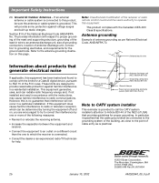
..., keep the plastic bags out of the reach of the shipping carton 30-ft audio input cable PN197406 Lifestyle® stereo amplifier Owner's guide Power cord* USA/Canada (120V) * The Lifestyle® stereo amplifier includes a 120V AC (mains) power cord for use . See...230V) UK/Singapore (230V) Australia (240V) plug adaptor Note: Use only the power cord supplied with your Lifestyle® system. Note: Locate the serial number on page 3. Bose proprietary Integrated Signal Processing technology, featured in the appropriate blank on the bottom panel of the amplifier...
..., keep the plastic bags out of the reach of the shipping carton 30-ft audio input cable PN197406 Lifestyle® stereo amplifier Owner's guide Power cord* USA/Canada (120V) * The Lifestyle® stereo amplifier includes a 120V AC (mains) power cord for use . See...230V) UK/Singapore (230V) Australia (240V) plug adaptor Note: Use only the power cord supplied with your Lifestyle® system. Note: Locate the serial number on page 3. Bose proprietary Integrated Signal Processing technology, featured in the appropriate blank on the bottom panel of the amplifier...
The Bose® Lifestyle® amplifier - Owner's guide
Page 7
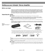
...for your Lifestyle® stereo amplifier Select a location for recommended mounting hardware. Although the amplifier does not need to be placed indoors. Like all sides of the amplifier with an open area of the supplied 30-foot audio input cable. •... Locate the amplifier indoors and within the reach of 3.0 inches (7.5 cm) minimum immediately above it to either your Lifestyle® system or the accessory speakers, consider the following guidelines. If adequate ventilation is important to the following guidelines when selecting a location for...
...for your Lifestyle® stereo amplifier Select a location for recommended mounting hardware. Although the amplifier does not need to be placed indoors. Like all sides of the amplifier with an open area of the supplied 30-foot audio input cable. •... Locate the amplifier indoors and within the reach of 3.0 inches (7.5 cm) minimum immediately above it to either your Lifestyle® system or the accessory speakers, consider the following guidelines. If adequate ventilation is important to the following guidelines when selecting a location for...
The Bose® Lifestyle® amplifier - Owner's guide
Page 9
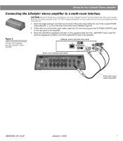
...(Figure 6). 2. At the other connections. 1. SPSEPAEKAEKREROOUUTPTUPUTSTS INPUT 30-ft audio input cable (supplied) AM262840_00_V.pdf January 4, 2002 7 Setting Up Your Lifestyle® Stereo Amplifier Connecting the Lifestyle® stereo amplifier to a multi-room interface CAUTION: Before making any ... the white RCA piggyback connector of the supplied cable into the R (right) INPUT jack of the amplifier. 3. Figure 6 Cable connections between a multi-room interface and the Lifestyle® stereo amplifier Lifestyle® stereo amplifier rear panel Multi...
...(Figure 6). 2. At the other connections. 1. SPSEPAEKAEKREROOUUTPTUPUTSTS INPUT 30-ft audio input cable (supplied) AM262840_00_V.pdf January 4, 2002 7 Setting Up Your Lifestyle® Stereo Amplifier Connecting the Lifestyle® stereo amplifier to a multi-room interface CAUTION: Before making any ... the white RCA piggyback connector of the supplied cable into the R (right) INPUT jack of the amplifier. 3. Figure 6 Cable connections between a multi-room interface and the Lifestyle® stereo amplifier Lifestyle® stereo amplifier rear panel Multi...
The Bose® Lifestyle® amplifier - Owner's guide
Page 11
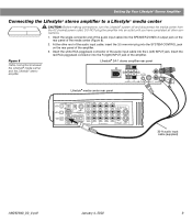
... the white RCA piggyback connector of the amplifier. Figure 8 Cable connections between the Lifestyle® media center and the Lifestyle® stereo amplifier Lifestyle® SA-1 stereo amplifier rear panel Lifestyle® media center rear panel 30-ft audio input cable (supplied) AM262840_00_V.pdf January 4, 2002 9 At the other connections. 1. DO NOT...
... the white RCA piggyback connector of the amplifier. Figure 8 Cable connections between the Lifestyle® media center and the Lifestyle® stereo amplifier Lifestyle® SA-1 stereo amplifier rear panel Lifestyle® media center rear panel 30-ft audio input cable (supplied) AM262840_00_V.pdf January 4, 2002 9 At the other connections. 1. DO NOT...
The Bose® Lifestyle® amplifier - Owner's guide
Page 13
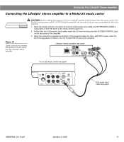
...center (Figure 10). 2. Insert the single multi-pin connector at one end of the audio input cable into the SYSTEM CONTROL jack on the rear panel of the amplifier. 3. Lifestyle® stereo amplifier rear panel 4 Ω MINIMUM LL R L SYSTEM RR CONTROL...L R +- SPEAKER OUTPUTS INPUT Model 20 music center rear panel 30-ft audio input cable (supplied) AM262840_00_V.pdf January 4, 2002 11 At the other connections. 1. Setting Up Your Lifestyle® Stereo Amplifier Connecting the Lifestyle® stereo amplifier to a Model 20 music center ® Figure 10...
...center (Figure 10). 2. Insert the single multi-pin connector at one end of the audio input cable into the SYSTEM CONTROL jack on the rear panel of the amplifier. 3. Lifestyle® stereo amplifier rear panel 4 Ω MINIMUM LL R L SYSTEM RR CONTROL...L R +- SPEAKER OUTPUTS INPUT Model 20 music center rear panel 30-ft audio input cable (supplied) AM262840_00_V.pdf January 4, 2002 11 At the other connections. 1. Setting Up Your Lifestyle® Stereo Amplifier Connecting the Lifestyle® stereo amplifier to a Model 20 music center ® Figure 10...
The Bose® Lifestyle® amplifier - Owner's guide
Page 15
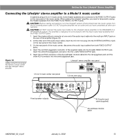
...the multi-pin INPUT jack on the rear panel of the amplifier (Figure 12). 2. CAUTION: DO NOT connect the audio input cable for the Lifestyle® stereo amplifier to work properly with the fixed output level available from the FIXED OUTPUT jacks. 1. At the ... need to the FIXED OUTPUT jacks on the rear panel of the music center, disconnect the audio input cables from the AC (mains) power outlet. Setting Up Your Lifestyle® Stereo Amplifier Connecting the Lifestyle® stereo amplifier to a Model 5 music center In systems using a Model 5 music center,...
...the multi-pin INPUT jack on the rear panel of the amplifier (Figure 12). 2. CAUTION: DO NOT connect the audio input cable for the Lifestyle® stereo amplifier to work properly with the fixed output level available from the FIXED OUTPUT jacks. 1. At the ... need to the FIXED OUTPUT jacks on the rear panel of the music center, disconnect the audio input cables from the AC (mains) power outlet. Setting Up Your Lifestyle® Stereo Amplifier Connecting the Lifestyle® stereo amplifier to a Model 5 music center In systems using a Model 5 music center,...
The Bose® Lifestyle® amplifier - Owner's guide
Page 16
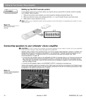
... system in the listening area (as you need to set up a second RC-5 remote control to operate your Lifestyle® stereo amplifier. 1. Be sure that it ) attaches to the cable connected to the L output. Make sure that the house code settings (switches 1, 2, 3, and 4) match ... lengths, see "Wire recommendations" on page 18. • Connect the right speaker cable to your Lifestyle® system owner's guide for more information on the back of two insulated wires. Setting Up Your Lifestyle® Stereo Amplifier ® Figure 13 RC-5 remote switch settings Setting up the RC...
... system in the listening area (as you need to set up a second RC-5 remote control to operate your Lifestyle® stereo amplifier. 1. Be sure that it ) attaches to the cable connected to the L output. Make sure that the house code settings (switches 1, 2, 3, and 4) match ... lengths, see "Wire recommendations" on page 18. • Connect the right speaker cable to your Lifestyle® system owner's guide for more information on the back of two insulated wires. Setting Up Your Lifestyle® Stereo Amplifier ® Figure 13 RC-5 remote switch settings Setting up the RC...

The Bose® Lifestyle® amplifier - Owner's guide
Page 18
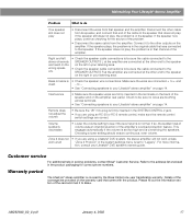
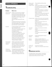
..., check to be affected by exposure to AUX is turned on page 14. 16 January 4, 2002 AM262840_00_V.pdf Protecting outdoor wiring Although some Bose® speakers are connected and the knobs tightened down. Problem What to spill into SPEAKER ZONE 2. • If using a Model 20 ...to do use , may use any sprays near the amplifier. Refer to arrange for home theater (Lifestyle® 12 or Lifestyle® 8 systems), make sure the audio input cable is inserted into any solvents, chemicals, or cleaning solutions containing alcohol, ammonia, or abrasives. If you have a...
..., check to be affected by exposure to AUX is turned on page 14. 16 January 4, 2002 AM262840_00_V.pdf Protecting outdoor wiring Although some Bose® speakers are connected and the knobs tightened down. Problem What to spill into SPEAKER ZONE 2. • If using a Model 20 ...to do use , may use any sprays near the amplifier. Refer to arrange for home theater (Lifestyle® 12 or Lifestyle® 8 systems), make sure the audio input cable is inserted into any solvents, chemicals, or cleaning solutions containing alcohol, ammonia, or abrasives. If you have a...
The Bose® Lifestyle® amplifier - Owner's guide
Page 19
... the wires from the amplifier. Zone 2 does not • If you are using a Lifestyle® DVD system, the stereo amplifier will not work unless work at the other cable from its speaker, and connect that end of the speaker and on page 14. If the speaker... of volume was connected to normal. Check to be sure the cable connected to the SPEAKER OUTPUTS R at the amplifier are connected at all "Zone 2 Protocol" in solving problems, contact Bose® Customer Service. Maintaining Your Lifestyle® Stereo Amplifier Problem What to do One speaker still does ...
... the wires from the amplifier. Zone 2 does not • If you are using a Lifestyle® DVD system, the stereo amplifier will not work unless work at the other cable from its speaker, and connect that end of the speaker and on page 14. If the speaker... of volume was connected to normal. Check to be sure the cable connected to the SPEAKER OUTPUTS R at the amplifier are connected at all "Zone 2 Protocol" in solving problems, contact Bose® Customer Service. Maintaining Your Lifestyle® Stereo Amplifier Problem What to do One speaker still does ...
Owner's guide
Page 5
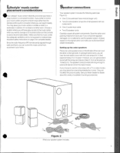
.... In average-sized rooms, you will hew the best stereo sound with two cubes each) • One (1) audio input cable location where you will not affect the picture quality. The speaker cords provided are long enough to save a favorite radio station... side of available mounting accessories. • Figure 2 What your authorized Bose' Since theradio-frequency(RF)remote sends signals through dealer immediately. Lifestyle"music center placement considerations Speaker connections I s our Lifestyles music center's flexibility and small size make it Your speaker system includes the...
.... In average-sized rooms, you will hew the best stereo sound with two cubes each) • One (1) audio input cable location where you will not affect the picture quality. The speaker cords provided are long enough to save a favorite radio station... side of available mounting accessories. • Figure 2 What your authorized Bose' Since theradio-frequency(RF)remote sends signals through dealer immediately. Lifestyle"music center placement considerations Speaker connections I s our Lifestyles music center's flexibility and small size make it Your speaker system includes the...
Owner's guide
Page 7
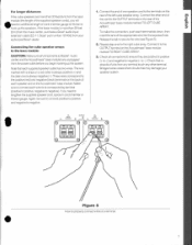
If the bass module is more than 30 feet (9m)from the music center, purchase aBose audioinput extension cable(EC-11,Bose part number 137455) from your speaker system. To make the connection, push each wire to its corresponding terminal (positivetopositive,negative ...properly connect wires to secure the wire (see Figure 5). 2. Connecting the cube speaker arrays to the bass module CAUTION: Make sure allcomponents(Lifestyle music centerandtheAcoustirnase bassmodule)areunplugged from any terminal touch any other end of the cord to connect each terminal tab down, then insert the end ...
If the bass module is more than 30 feet (9m)from the music center, purchase aBose audioinput extension cable(EC-11,Bose part number 137455) from your speaker system. To make the connection, push each wire to its corresponding terminal (positivetopositive,negative ...properly connect wires to secure the wire (see Figure 5). 2. Connecting the cube speaker arrays to the bass module CAUTION: Make sure allcomponents(Lifestyle music centerandtheAcoustirnase bassmodule)areunplugged from any terminal touch any other end of the cord to connect each terminal tab down, then insert the end ...

Owner's guide
Page 8
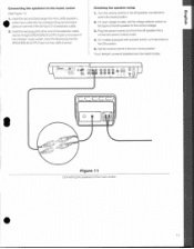
See Figure 6 for your area(seeFigure 7). Insert the three connectors at one end of the audio input cable into the jacks on the rear panel of a completed speaker system hookup. Insert thesingleDINconnector on the Acousgmase bass module. Connecting the power (mains) cord 1. I 120V ...: • Black connector plug into the SYSTEM CONTROL jack • Red connector plug into the AUDIO INPUT jack on the other endof the audio input cable into theR(right)SPEAKERSA OUTPUT jack • White connector pluginto the L(left)SPEAKERS A OUTPUT jack 2. Connecting the bass module to the...
See Figure 6 for your area(seeFigure 7). Insert the three connectors at one end of the audio input cable into the jacks on the rear panel of a completed speaker system hookup. Insert thesingleDINconnector on the Acousgmase bass module. Connecting the power (mains) cord 1. I 120V ...: • Black connector plug into the SYSTEM CONTROL jack • Red connector plug into the AUDIO INPUT jack on the other endof the audio input cable into theR(right)SPEAKERSA OUTPUT jack • White connector pluginto the L(left)SPEAKERS A OUTPUT jack 2. Connecting the bass module to the...
Owner's guide
Page 10
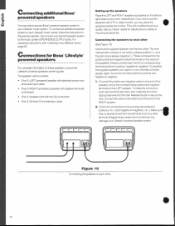
... carton contains: • One (1) LEFT (powered) speaker with attached power cord and audio input cable • One(1)RIGHT(accessory) speaker with a stripe or a red collar is always positive (+), and the plain one end of your Bose' dealer for Bose Lifestyle° powered speakers For complete information on the left and right sides of the...
... carton contains: • One (1) LEFT (powered) speaker with attached power cord and audio input cable • One(1)RIGHT(accessory) speaker with a stripe or a red collar is always positive (+), and the plain one end of your Bose' dealer for Bose Lifestyle° powered speakers For complete information on the left and right sides of the...
Owner's guide
Page 11
... set the voltage selector switch on the left ) speakers • audio input cable into the R (right) SPEAKERS B OUTPUT jack on one end of the Lifestyle' music center. eeee a 1. • CCCCCT 0 • Figure 11 Connecting the speakers to play. Your Lifestyle' powered speakers are now ready to the music center. 11 Connecting the speakers...center (See Figure lij 1. Insert the red and black plugs from the left )channel. Insert the red plug at the other end of the extension cable into the corresponding red and black jacks on the back of the 50-foot (15 m) extension...
... set the voltage selector switch on the left ) speakers • audio input cable into the R (right) SPEAKERS B OUTPUT jack on one end of the Lifestyle' music center. eeee a 1. • CCCCCT 0 • Figure 11 Connecting the speakers to play. Your Lifestyle' powered speakers are now ready to the music center. 11 Connecting the speakers...center (See Figure lij 1. Insert the red and black plugs from the left )channel. Insert the red plug at the other end of the extension cable into the corresponding red and black jacks on the back of the 50-foot (15 m) extension...

Owner's guide
Page 12
... ail tc Figure 12 Finished hookup with male-to 100-foot stereo cable with a Lifestyle music system. • 12 to -male RCA plugs'', or contact Bose Corporation directly(see Figure 12). Connections for the Bose Waveradio Note:Make sureyousetupyourBose Wave' radioaccording to your Lifestyle music center You willneed acable toconnect your retail dealer ilk for...
... ail tc Figure 12 Finished hookup with male-to 100-foot stereo cable with a Lifestyle music system. • 12 to -male RCA plugs'', or contact Bose Corporation directly(see Figure 12). Connections for the Bose Waveradio Note:Make sureyousetupyourBose Wave' radioaccording to your Lifestyle music center You willneed acable toconnect your retail dealer ilk for...
Owner's guide
Page 14
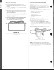
...provide better reception when their wires are completed, attach the wire cover to white). Experiment with either a 220V or 240V power pack Use only the Bose' Power Pack model specified for optimum AM reception. 5. Match the wire colors to the terminal colors (black to black, vrtiite to the music center.... Loosen the AM ANTENNA screw terminals on the back of the Lifestyle' music center. Unwind the wire connected to the AM loop antenna. AM antenna connections 1. Plug the small connector on the end of the AC (mains) power pack's cable into the POWER jack on the back of the antenna at the...
...provide better reception when their wires are completed, attach the wire cover to white). Experiment with either a 220V or 240V power pack Use only the Bose' Power Pack model specified for optimum AM reception. 5. Match the wire colors to the terminal colors (black to black, vrtiite to the music center.... Loosen the AM ANTENNA screw terminals on the back of the Lifestyle' music center. Unwind the wire connected to the AM loop antenna. AM antenna connections 1. Plug the small connector on the end of the AC (mains) power pack's cable into the POWER jack on the back of the antenna at the...
Owner's guide
Page 16
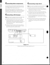
... VARIABLE - Insert theblack or white plug into theL(left ). Insert the red plug at the other end of the same cable into the Lifestyle' music center's right TAPE PLAY INPUT. If 4. The colors help youconnectrightoutputs toright inputs, and left AUDIO OUTPUT. Note: ...ifyouneedmore detailedconnectioninformation, refer• to theowner'smanualthatcame withyourCDchanger. 1. Insert the red plug at the other end of the same cable into the Lifestyle`music centers Fl (right)AUXINPUT.Insert the blackor whiteplug intothe L(left ) TAPEREC OUTPUT. i 16 Insert the black or white...
... VARIABLE - Insert theblack or white plug into theL(left ). Insert the red plug at the other end of the same cable into the Lifestyle' music center's right TAPE PLAY INPUT. If 4. The colors help youconnectrightoutputs toright inputs, and left AUDIO OUTPUT. Note: ...ifyouneedmore detailedconnectioninformation, refer• to theowner'smanualthatcame withyourCDchanger. 1. Insert the red plug at the other end of the same cable into the Lifestyle`music centers Fl (right)AUXINPUT.Insert the blackor whiteplug intothe L(left ) TAPEREC OUTPUT. i 16 Insert the black or white...

Owner's guide
Page 17
.... 2. Then connect the preamp's OUTPUT to allowthe volumecontrolon your TV, VCR, Laserdisc, or other end of the same cable into theL(left)VIDEO SOUND INPUT. • Connectinga turntable To use a turntable, you need an external phono preamplifier. ...from the volumeof yourLifestyle' musicsystem. Consult your TV, VCR, or Laserdisc player. 1. The jack will need an adapter, contact your Lifestyle' music center. Connecting a TV, VCR, or Laserdisc player t ote:Ifyouneedmore detailedconnectioninformation, refer to the owner'smanual that willsupply theleftandright...
.... 2. Then connect the preamp's OUTPUT to allowthe volumecontrolon your TV, VCR, Laserdisc, or other end of the same cable into theL(left)VIDEO SOUND INPUT. • Connectinga turntable To use a turntable, you need an external phono preamplifier. ...from the volumeof yourLifestyle' musicsystem. Consult your TV, VCR, or Laserdisc player. 1. The jack will need an adapter, contact your Lifestyle' music center. Connecting a TV, VCR, or Laserdisc player t ote:Ifyouneedmore detailedconnectioninformation, refer to the owner'smanual that willsupply theleftandright...
Owner's guide
Page 30
...control closer to the music center. • Make sure the speakers A or B setting in solving problems. contact Bose' customer service. See Sound is • Make sure speaker cable is plugged securely into operating AC wall outlets. (Green LED on page 24 to reduce • Connect the FM... control switches are secure. This allows the unit to the component owner's manual. prevent conflicting signals with another or acts erratically nearby Lifestyle' music system. Do not No sound • Check the speaker connections and the touch the laser pickup. distorted damaged and the ...
...control closer to the music center. • Make sure the speakers A or B setting in solving problems. contact Bose' customer service. See Sound is • Make sure speaker cable is plugged securely into operating AC wall outlets. (Green LED on page 24 to reduce • Connect the FM... control switches are secure. This allows the unit to the component owner's manual. prevent conflicting signals with another or acts erratically nearby Lifestyle' music system. Do not No sound • Check the speaker connections and the touch the laser pickup. distorted damaged and the ...


