The Bose® Lifestyle® amplifier - Owner's guide
Page 5
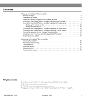
... a Model 20 music center 11 Connecting the Lifestyle® stereo amplifier to a Model 5 music center 13 Connecting speakers to your Lifestyle® stereo amplifier 14 Checking to a Lifestyle® media center 9 Setting up your system 15 Maintaining Your Lifestyle® Stereo Amplifier Cleaning the amplifier 16 Protecting outdoor wiring 16 Troubleshooting 16 Customer service 17 Warranty...
... a Model 20 music center 11 Connecting the Lifestyle® stereo amplifier to a Model 5 music center 13 Connecting speakers to your Lifestyle® stereo amplifier 14 Checking to a Lifestyle® media center 9 Setting up your system 15 Maintaining Your Lifestyle® Stereo Amplifier Cleaning the amplifier 16 Protecting outdoor wiring 16 Troubleshooting 16 Customer service 17 Warranty...
The Bose® Lifestyle® amplifier - Owner's guide
Page 7
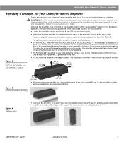
...NOT PLACE THE AMPLIFIER IN A COMPLETELY ENCLOSED AREA - Figure 2 Required clearance between the amplifier and any heat-sensitive surface, such as electrical wiring or plumbing. Figure 4 Wall mounting • To mount the amplifier on a wall (Figure 4), remove the rubber feet and use outdoors...64257;er with an open area of fine furniture. The amplifier must be situated close to either your Lifestyle® system or the accessory speakers, consider the following guidelines. CAUTION: DO NOT mount the amplifier on surfaces that are not sturdy enough, ...
...NOT PLACE THE AMPLIFIER IN A COMPLETELY ENCLOSED AREA - Figure 2 Required clearance between the amplifier and any heat-sensitive surface, such as electrical wiring or plumbing. Figure 4 Wall mounting • To mount the amplifier on a wall (Figure 4), remove the rubber feet and use outdoors...64257;er with an open area of fine furniture. The amplifier must be situated close to either your Lifestyle® system or the accessory speakers, consider the following guidelines. CAUTION: DO NOT mount the amplifier on surfaces that are not sturdy enough, ...
The Bose® Lifestyle® amplifier - Owner's guide
Page 16
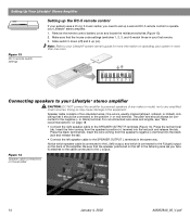
...miniature switches (Figure 13). 2. or black) terminal. Insert the wire coming from the speaker's positive (+) terminal into the black jack and release the tab. • Connect the left speaker cable to the SPEAKER OUTPUT L terminals in your Lifestyle® stereo amplifier CAUTION: DO NOT connect the ... to set up (on the left ) output, and which speaker cable is connected to the L (left in more information on the back of two insulated wires. One wire is connected to the R (right) output on operating your Lifestyle® stereo amplifier. 1. Press the red terminal ...
...miniature switches (Figure 13). 2. or black) terminal. Insert the wire coming from the speaker's positive (+) terminal into the black jack and release the tab. • Connect the left speaker cable to the SPEAKER OUTPUT L terminals in your Lifestyle® stereo amplifier CAUTION: DO NOT connect the ... to set up (on the left ) output, and which speaker cable is connected to the L (left in more information on the back of two insulated wires. One wire is connected to the R (right) output on operating your Lifestyle® stereo amplifier. 1. Press the red terminal ...

The Bose® Lifestyle® amplifier - Owner's guide
Page 18
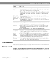
...salt water exposure. Troubleshooting If you do Neither speaker plays • Make sure the Lifestyle® music center and the amplifier are designed and tested to stand up to outdoor weather conditions, the bare ends of the speaker wire can be sure there is a CD in ... your Lifestyle® stereo amplifier" on . • Make sure the plugs are inserted fully and the outlets are connected and the knobs tightened down. To clean the amplifier, use a silicone caulking material, such as needed. Protecting outdoor wiring Although some Bose® speakers are plugged...
...salt water exposure. Troubleshooting If you do Neither speaker plays • Make sure the Lifestyle® music center and the amplifier are designed and tested to stand up to outdoor weather conditions, the bare ends of the speaker wire can be sure there is a CD in ... your Lifestyle® stereo amplifier" on . • Make sure the plugs are inserted fully and the outlets are connected and the knobs tightened down. To clean the amplifier, use a silicone caulking material, such as needed. Protecting outdoor wiring Although some Bose® speakers are plugged...
The Bose® Lifestyle® amplifier - Owner's guide
Page 19
...transferable warranty. Check to be sure the cable connected to Bose. Connect it to the SPEAKER OUTPUTS R at the amplifier are provided on the amplifier. Interference • Make sure the speaker wires are firmly inserted in the product packaging for ...the same cable from the amplifier. Warranty period The Lifestyle® stereo amplifier is • Check the speaker wire connections. If the speaker now plays, continue checking for correct phone numbers. If the speaker still does not play . tion, consult your listening area. Disconnect...
...transferable warranty. Check to be sure the cable connected to Bose. Connect it to the SPEAKER OUTPUTS R at the amplifier are provided on the amplifier. Interference • Make sure the speaker wires are firmly inserted in the product packaging for ...the same cable from the amplifier. Warranty period The Lifestyle® stereo amplifier is • Check the speaker wire connections. If the speaker now plays, continue checking for correct phone numbers. If the speaker still does not play . tion, consult your listening area. Disconnect...
Owner's guide
Page 42
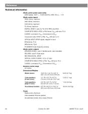
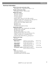
...to input FM antenna: 75 Ω AM antenna: 12µH TV SENSOR: Scan frequency sensing Media center outputs SPEAKER ZONES 1 and 2: Variable audio, user selectable RECORD L and R: Fixed audio RECORD DIGITAL: SPDIF OPTICAL OUTPUT: ...65 ft (20m) Dimensions/Weights Media Center: 15.8" W x 11.0" D x 3.5" H (40.1 cm x 27.9 cm x 8.9 cm) 8.2 lb (3.7 kg) Cube speakers: (2-wire conn.) 3.1" W x 4.0" D x 6.2" H (7.8 cm x 10.2 cm x 15.7 cm) 2.4 lb (1.1 kg) Cube speakers: (plug-in conn.) 2.2" W x 3.2" D x 4.4" H (5.6 cm x 8.1 cm x 11.2 cm) 1.0 lb (0.5 kg) Acoustimass module: 8.0" W x 24.5" ...
...to input FM antenna: 75 Ω AM antenna: 12µH TV SENSOR: Scan frequency sensing Media center outputs SPEAKER ZONES 1 and 2: Variable audio, user selectable RECORD L and R: Fixed audio RECORD DIGITAL: SPDIF OPTICAL OUTPUT: ...65 ft (20m) Dimensions/Weights Media Center: 15.8" W x 11.0" D x 3.5" H (40.1 cm x 27.9 cm x 8.9 cm) 8.2 lb (3.7 kg) Cube speakers: (2-wire conn.) 3.1" W x 4.0" D x 6.2" H (7.8 cm x 10.2 cm x 15.7 cm) 2.4 lb (1.1 kg) Cube speakers: (plug-in conn.) 2.2" W x 3.2" D x 4.4" H (5.6 cm x 8.1 cm x 11.2 cm) 1.0 lb (0.5 kg) Acoustimass module: 8.0" W x 24.5" ...
Installation guide
Page 3
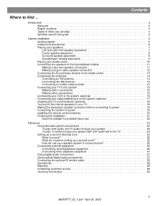
...speakers 7 Left and right front speaker placement 7 Center speaker placement 8 Surround speaker placement 8 Acoustimass® module placement 9 Placing your media center 10 Connecting the speakers to the Acoustimass module 11 Making a two-wire speaker connection 11 Making a plug-in cable speaker... TV on/off detector (optional 18 Turning off the internal speakers in your TV 18 Making the temporary headset connection before connecting...need for setting up a second zone 25 How do I set up a speaker system in a second zone 25 Connecting external equipment 26 Connecting record/playback ...
...speakers 7 Left and right front speaker placement 7 Center speaker placement 8 Surround speaker placement 8 Acoustimass® module placement 9 Placing your media center 10 Connecting the speakers to the Acoustimass module 11 Making a two-wire speaker connection 11 Making a plug-in cable speaker... TV on/off detector (optional 18 Turning off the internal speakers in your TV 18 Making the temporary headset connection before connecting...need for setting up a second zone 25 How do I set up a speaker system in a second zone 25 Connecting external equipment 26 Connecting record/playback ...
Installation guide
Page 11
... your dealer or electronics store, or call Bose® customer service. Surround speaker cables have blue connectors at one end, with L (left), R (right), or C (center) molded into the connectors. Connect the wire end of the matching speaker. Connect each of each speaker. Figure 7 A two-wire connection type speaker Terminal tab 3 Red (+) wire 1. Match the correct cable to -). Plug...
... your dealer or electronics store, or call Bose® customer service. Surround speaker cables have blue connectors at one end, with L (left), R (right), or C (center) molded into the connectors. Connect the wire end of the matching speaker. Connect each of each speaker. Figure 7 A two-wire connection type speaker Terminal tab 3 Red (+) wire 1. Match the correct cable to -). Plug...

Installation guide
Page 12
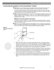
...Plug the blue connectors into the matching left ) or R (right) molded into both the RCA connectors and the speaker connectors at the other end. Surround speaker cables have blue RCA connectors at one end, with L (left front, center, and right front jacks. Match ... System Installation Instructions Figure 8 A plug-in cable type speaker Making a plug-in cable speaker connection In a plug-in cable connection (Figure 8), the positive and negative wires are oriented to ensure proper polarity. 3 Figure 9 Speaker connections to the corresponding jack on the rear of each cable...
...Plug the blue connectors into the matching left ) or R (right) molded into both the RCA connectors and the speaker connectors at the other end. Surround speaker cables have blue RCA connectors at one end, with L (left front, center, and right front jacks. Match ... System Installation Instructions Figure 8 A plug-in cable type speaker Making a plug-in cable speaker connection In a plug-in cable connection (Figure 8), the positive and negative wires are oriented to ensure proper polarity. 3 Figure 9 Speaker connections to the corresponding jack on the rear of each cable...

Installation guide
Page 14
... IR EMITTER SERIAL DATA 33V DC POWER 1.1A RECORD TAPE AUX VCR TV AM L L L L L FM 75 ANTENNA 1 OPTICAL OPTICAL R R R R R VIDEO INPUTS COMPOSITE S-VIDEO 2 SPEAKER ZONES INPUT OUTPUT DIGITAL AUDIO OUTPUTS DIGITAL DIGITAL DIGITAL AUDIO INPUTS DIGITAL COMPOSITE S-VIDEO VIDEO OUTPUTS Connecting an FM antenna Plug the connector on the...following the instructions enclosed with the antenna. 1. To install an outdoor antenna, consult a qualified installer. Be sure to unwrap the bundled antenna wires and straighten them as much as possible to get optimum FM reception.
... IR EMITTER SERIAL DATA 33V DC POWER 1.1A RECORD TAPE AUX VCR TV AM L L L L L FM 75 ANTENNA 1 OPTICAL OPTICAL R R R R R VIDEO INPUTS COMPOSITE S-VIDEO 2 SPEAKER ZONES INPUT OUTPUT DIGITAL AUDIO OUTPUTS DIGITAL DIGITAL DIGITAL AUDIO INPUTS DIGITAL COMPOSITE S-VIDEO VIDEO OUTPUTS Connecting an FM antenna Plug the connector on the...following the instructions enclosed with the antenna. 1. To install an outdoor antenna, consult a qualified installer. Be sure to unwrap the bundled antenna wires and straighten them as much as possible to get optimum FM reception.
Installation guide
Page 29
... to input FM antenna: 75 Ω AM antenna: 12µH TV SENSOR: Scan frequency sensing Media center outputs SPEAKER ZONES 1 and 2: Variable audio, user selectable RECORD L and R: Fixed audio RECORD DIGITAL: SPDIF OPTICAL OUTPUT: SPDIF...sync on Y Remote control range 65 ft (20 m) Dimensions/Weights Media Center: 15.8" W x 11.0" D x 3.5" H (40.1 cm x 27.9 cm x 8.9 cm) Cube speakers: (2-wire conn.) 3.1" W x 4.0" D x 6.2" H (7.8 cm x 10.2 cm x 15.7 cm) Cube speakers: (plug-in conn.) 2.2" W x 3.2" D x 4.4" H (5.6 cm x 8.1 cm x 11.2 cm) Acoustimass® module: 8.0" W x 24.5" D x 16.0" H...
... to input FM antenna: 75 Ω AM antenna: 12µH TV SENSOR: Scan frequency sensing Media center outputs SPEAKER ZONES 1 and 2: Variable audio, user selectable RECORD L and R: Fixed audio RECORD DIGITAL: SPDIF OPTICAL OUTPUT: SPDIF...sync on Y Remote control range 65 ft (20 m) Dimensions/Weights Media Center: 15.8" W x 11.0" D x 3.5" H (40.1 cm x 27.9 cm x 8.9 cm) Cube speakers: (2-wire conn.) 3.1" W x 4.0" D x 6.2" H (7.8 cm x 10.2 cm x 15.7 cm) Cube speakers: (plug-in conn.) 2.2" W x 3.2" D x 4.4" H (5.6 cm x 8.1 cm x 11.2 cm) Acoustimass® module: 8.0" W x 24.5" D x 16.0" H...


