Owner's guide
Page 8
... does not require a comb filter to mean Digital Video Disc or Digital Versatile Disc. Introduction Chapter - In DVD-Video, a division of an analog signal. IR - The film picture becomes a "letterbox" within the video. This is based on a single CD. PCM - DVD Video - Letterbox - MPEG-1 Layer III audio. PAL - The...
... does not require a comb filter to mean Digital Video Disc or Digital Versatile Disc. Introduction Chapter - In DVD-Video, a division of an analog signal. IR - The film picture becomes a "letterbox" within the video. This is based on a single CD. PCM - DVD Video - Letterbox - MPEG-1 Layer III audio. PAL - The...

Owner's guide
Page 20
..., 2001 AM259776_01_V.pdf Press shown. Press until your TV brand name is shown. 7. See the "Remote control setup submenu" on your LIFESTYLE® remote control, you cannot turn off and on again when pressing the TV Power button. Select Remote Control Setup and press Enter.... external sources Follow the instructions in your remote is programmed to control. Programming your LIFESTYLE® remote to control your VCR If you want to communicate with your TV. 2. An infrared (IR) emitter is included behind the media center display to control your TV with any ...
..., 2001 AM259776_01_V.pdf Press shown. Press until your TV brand name is shown. 7. See the "Remote control setup submenu" on your LIFESTYLE® remote control, you cannot turn off and on again when pressing the TV Power button. Select Remote Control Setup and press Enter.... external sources Follow the instructions in your remote is programmed to control. Programming your LIFESTYLE® remote to control your VCR If you want to communicate with your TV. 2. An infrared (IR) emitter is included behind the media center display to control your TV with any ...
Owner's guide
Page 32
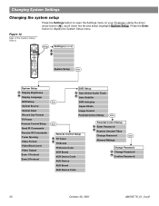
...) System Setup Enter System Setup Display Brightness Display Language DVD Setup Optical Source Optical Input Record Out Format TV Power Remote Control Setup Send IR Commands Receive IR Commands Tuner Spacing Video Format Video Black Level Video Output Zone 1 Protocol Zone 2 Protocol DVD Setup Auto Select Audio Track Auto Subtitle Enter DVD...
...) System Setup Enter System Setup Display Brightness Display Language DVD Setup Optical Source Optical Input Record Out Format TV Power Remote Control Setup Send IR Commands Receive IR Commands Tuner Spacing Video Format Video Black Level Video Output Zone 1 Protocol Zone 2 Protocol DVD Setup Auto Select Audio Track Auto Subtitle Enter DVD...
Owner's guide
Page 33
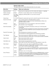
...Coded Modulation (PCM) on some TVs. You must turn on your TV, VCR and AUX components. Off Your system only sends IR commands to other IR remote controls. Extended Sets a black level that may be preferred for AM/FM radio to the USA standard. Normal Legacy Provides... on your system. Auto Manual Automatically turns on -screen display menus in zone 1 for Bose powered speaker systems Acoustimass 5P and Acoustimass 20P. This setting may be useful to teach LIFESTYLE® remote commands to control your TV separately. European Sets channel spacing for DVD playback on...
...Coded Modulation (PCM) on some TVs. You must turn on your TV, VCR and AUX components. Off Your system only sends IR commands to other IR remote controls. Extended Sets a black level that may be preferred for AM/FM radio to the USA standard. Normal Legacy Provides... on your system. Auto Manual Automatically turns on -screen display menus in zone 1 for Bose powered speaker systems Acoustimass 5P and Acoustimass 20P. This setting may be useful to teach LIFESTYLE® remote commands to control your TV separately. European Sets channel spacing for DVD playback on...
Owner's guide
Page 35
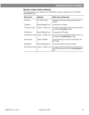
... Device Code: Code1 / Code2 / etc. Chooses the VCR brand. AM259776_01_V.pdf October 30, 2001 33 Chooses the IR code that the VCR remote control uses. Chooses the IR code that the remote control of device connected to test. AUX Brand: Brand1/Brand2/ etc. AUX Device Code: Code1.... AUX Device: Cable / Satellite Chooses the type of the AUX component uses. Chooses the IR code that selects the channel for viewing. Press TV Power to operate your LIFESTYLE® remote to test. Chooses the AUX component brand. Changing System Settings Remote control setup ...
... Device Code: Code1 / Code2 / etc. Chooses the VCR brand. AM259776_01_V.pdf October 30, 2001 33 Chooses the IR code that the VCR remote control uses. Chooses the IR code that the remote control of device connected to test. AUX Brand: Brand1/Brand2/ etc. AUX Device Code: Code1.... AUX Device: Cable / Satellite Chooses the type of the AUX component uses. Chooses the IR code that selects the channel for viewing. Press TV Power to operate your LIFESTYLE® remote to test. Chooses the AUX component brand. Changing System Settings Remote control setup ...
Owner's guide
Page 41
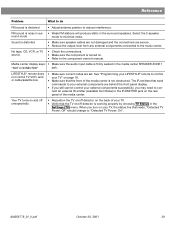
... cable is distorted • Make sure speaker cables are not damaged and the connections are secure. • Reduce the output level from Bose) to the IR EMITTER jack on page 18. • Make sure that send commands to your external components are set. When you turn on . •...successfully, you still cannot control your TV" on the rear panel of the media center is distorted • Adjust antenna position to reduce interference. LIFESTYLE® remote does not control TV, VCR, and/ or cable/satellite box • Make sure correct codes are behind the front panel display....
... cable is distorted • Make sure speaker cables are not damaged and the connections are secure. • Reduce the output level from Bose) to the IR EMITTER jack on page 18. • Make sure that send commands to your external components are set. When you turn on . •...successfully, you still cannot control your TV" on the rear panel of the media center is distorted • Adjust antenna position to reduce interference. LIFESTYLE® remote does not control TV, VCR, and/ or cable/satellite box • Make sure correct codes are behind the front panel display....
Installation guide
Page 3
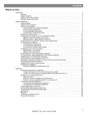
... 26 Connecting record/playback equipment 26 Connecting other playback equipment 27 Using digital audio connections 27 Using optical digital audio connections 27 Connecting the optional IR emitter cable 28 Accessories 28 Warranty 28 Contacting customer service 28 Technical information 29 3 AM259777_02_V.pdf • April 23, 2002
... 26 Connecting record/playback equipment 26 Connecting other playback equipment 27 Using digital audio connections 27 Using optical digital audio connections 27 Connecting the optional IR emitter cable 28 Accessories 28 Warranty 28 Contacting customer service 28 Technical information 29 3 AM259777_02_V.pdf • April 23, 2002

Installation guide
Page 6
... TV on/off detector Rubber feet for Acoustimass® module OR Rubber feet for cube speakers Batteries Remote control AM loop antenna FM antenna Optional IR emitter cable Discs 1 & 2 Media center power supply Headset for custom equalization process Media center power supply 120 VAC power cord (US/Canada) Acoustimass module 120...
... TV on/off detector Rubber feet for Acoustimass® module OR Rubber feet for cube speakers Batteries Remote control AM loop antenna FM antenna Optional IR emitter cable Discs 1 & 2 Media center power supply Headset for custom equalization process Media center power supply 120 VAC power cord (US/Canada) Acoustimass module 120...

Installation guide
Page 13
... the jack, the connector locks in place. Note: Refer to "Setting up ) into the AUDIO INPUT jack on the connection to media center TV SENSOR IR EMITTER SERIAL DATA 33V DC POWER 1.1A RECORD TAPE AUX VCR TV AM L L L L L FM 75 ANTENNA 1 1 OPTICAL OPTICAL R R R R R VIDEO INPUTS COMPOSITE S-VIDEO 2 SPEAKER ZONES INPUT...
... the jack, the connector locks in place. Note: Refer to "Setting up ) into the AUDIO INPUT jack on the connection to media center TV SENSOR IR EMITTER SERIAL DATA 33V DC POWER 1.1A RECORD TAPE AUX VCR TV AM L L L L L FM 75 ANTENNA 1 1 OPTICAL OPTICAL R R R R R VIDEO INPUTS COMPOSITE S-VIDEO 2 SPEAKER ZONES INPUT...

Installation guide
Page 14
..., contact your home. To connect to your cable TV provider for the AM and FM antennas AM antenna lead FM dipole antenna lead TV SENSOR IR EMITTER SERIAL DATA 33V DC POWER 1.1A RECORD TAPE AUX VCR TV AM L L L L L FM 75 ANTENNA 1 OPTICAL OPTICAL R R R R R VIDEO INPUTS COMPOSITE S-VIDEO 2 SPEAKER ZONES INPUT...
..., contact your home. To connect to your cable TV provider for the AM and FM antennas AM antenna lead FM dipole antenna lead TV SENSOR IR EMITTER SERIAL DATA 33V DC POWER 1.1A RECORD TAPE AUX VCR TV AM L L L L L FM 75 ANTENNA 1 OPTICAL OPTICAL R R R R R VIDEO INPUTS COMPOSITE S-VIDEO 2 SPEAKER ZONES INPUT...

Installation guide
Page 15
... video cable (with yellow connectors), connect the COMPOSITE video output on the rear panel of the media center to use as described below. TV SENSOR IR EMITTER SERIAL DATA 33V DC POWER 1.1A RECORD TAPE AUX VCR TV AM L L L L L FM 75 ANTENNA 1 OPTICAL OPTICAL R R R R R VIDEO INPUTS COMPOSITE S-VIDEO 2 SPEAKER ZONES INPUT...
... video cable (with yellow connectors), connect the COMPOSITE video output on the rear panel of the media center to use as described below. TV SENSOR IR EMITTER SERIAL DATA 33V DC POWER 1.1A RECORD TAPE AUX VCR TV AM L L L L L FM 75 ANTENNA 1 OPTICAL OPTICAL R R R R R VIDEO INPUTS COMPOSITE S-VIDEO 2 SPEAKER ZONES INPUT...
Installation guide
Page 16
...of video connection used with your TV must match the type of connection used with the cables. See your LIFESTYLE® 28/35 system operating guide for the Y, Pb, and Pr jacks and the Bose® component video adapter (Figure 13). If you will send the correct signals to -VCR video and... audio connections TV SENSOR IR EMITTER SERIAL DATA 33V DC POWER 1.1A RECORD TAPE AUX VCR TV AM L L L L L FM 75 ANTENNA...
...of video connection used with your TV must match the type of connection used with the cables. See your LIFESTYLE® 28/35 system operating guide for the Y, Pb, and Pr jacks and the Bose® component video adapter (Figure 13). If you will send the correct signals to -VCR video and... audio connections TV SENSOR IR EMITTER SERIAL DATA 33V DC POWER 1.1A RECORD TAPE AUX VCR TV AM L L L L L FM 75 ANTENNA...
Installation guide
Page 17
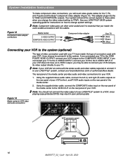
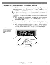
... box to the system (optional) The type of video connection used with your TV and VCR must match the type of connection used ) TV SENSOR IR EMITTER SERIAL DATA 33V DC POWER 1.1A RECORD TAPE AUX VCR TV AM L L L L L FM 75 ANTENNA 1 OPTICAL OPTICAL R R R R R VIDEO INPUTS COMPOSITE S-VIDEO ... the stereo audio and video cables required to connect it to the system. If you connected your TV to your LIFESTYLE® system, contact your local electronics store or authorized Bose dealer. The AUX jacks are required for your cable/satellite box to the L and R AUX audio inputs on...
... box to the system (optional) The type of video connection used with your TV and VCR must match the type of connection used ) TV SENSOR IR EMITTER SERIAL DATA 33V DC POWER 1.1A RECORD TAPE AUX VCR TV AM L L L L L FM 75 ANTENNA 1 OPTICAL OPTICAL R R R R R VIDEO INPUTS COMPOSITE S-VIDEO ... the stereo audio and video cables required to connect it to the system. If you connected your TV to your LIFESTYLE® system, contact your local electronics store or authorized Bose dealer. The AUX jacks are required for your cable/satellite box to the L and R AUX audio inputs on...

Installation guide
Page 18
... operating and you will not work with LCD and plasma TVs, so if you are using the mounting strip Media center rear panel TV SENSOR IR EMITTER SERIAL DATA 33V DC POWER 1.1A RECORD TAPE AUX VCR TV AM L L L L L FM 75 ANTENNA 1 OPTICAL OPTICAL R R R R R VIDEO INPUTS COMPOSITE S-VIDEO 2 ...mounting strip yet to select "Internal Speakers: Off" (your TV should not be different). This enables the media center to TV sound through your LIFESTYLE® system, the speakers in your on-screen message may want to "Testing the TV on/off detector" in your TV owner's guide for...
... operating and you will not work with LCD and plasma TVs, so if you are using the mounting strip Media center rear panel TV SENSOR IR EMITTER SERIAL DATA 33V DC POWER 1.1A RECORD TAPE AUX VCR TV AM L L L L L FM 75 ANTENNA 1 OPTICAL OPTICAL R R R R R VIDEO INPUTS COMPOSITE S-VIDEO 2 ...mounting strip yet to select "Internal Speakers: Off" (your TV should not be different). This enables the media center to TV sound through your LIFESTYLE® system, the speakers in your on-screen message may want to "Testing the TV on/off detector" in your TV owner's guide for...

Installation guide
Page 19
... 23, 2002 Turn the Acoustimass module POWER switch to power Connect the two AC power (mains) cords in the final setup steps TV SENSOR IR EMITTER SERIAL DATA 33V DC POWER 1.1A RECORD TAPE AUX VCR TV AM L L L L L FM 75 ANTENNA 1 OPTICAL OPTICAL R RR R R R VIDEO INPUTS COMPOSITE S-VIDEO 2 SPEAKER ZONES...
... 23, 2002 Turn the Acoustimass module POWER switch to power Connect the two AC power (mains) cords in the final setup steps TV SENSOR IR EMITTER SERIAL DATA 33V DC POWER 1.1A RECORD TAPE AUX VCR TV AM L L L L L FM 75 ANTENNA 1 OPTICAL OPTICAL R RR R R R VIDEO INPUTS COMPOSITE S-VIDEO 2 SPEAKER ZONES...
Installation guide
Page 25
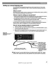
...connect the zone 2 speaker system to the SPEAKER ZONES 2 connector on the rear panel of the media center. • A second LIFESTYLE® system remote control to -zone 2 connections TV SENSOR IR EMITTER SERIAL DATA 33V DC POWER 1.1A RECORD TAPE AUX VCR TV AM L L L L L FM 75 ANTENNA 1 OPTICAL ...2, use only cables that is marked "FIX") Zone 2 speaker connections Control Left channel Right channel Note: Before using your dealer or contact Bose for information on the rear panel of rooms (including outdoor areas), is a zone? How do I set up a second listening zone" in...
...connect the zone 2 speaker system to the SPEAKER ZONES 2 connector on the rear panel of the media center. • A second LIFESTYLE® system remote control to -zone 2 connections TV SENSOR IR EMITTER SERIAL DATA 33V DC POWER 1.1A RECORD TAPE AUX VCR TV AM L L L L L FM 75 ANTENNA 1 OPTICAL ...2, use only cables that is marked "FIX") Zone 2 speaker connections Control Left channel Right channel Note: Before using your dealer or contact Bose for information on the rear panel of rooms (including outdoor areas), is a zone? How do I set up a second listening zone" in...

Installation guide
Page 26
... (RECORD) connections for a cassette tape deck. A Y adapter can be used to connect mono sources. Figure 25 Record/playback connections Media center connector panel TV SENSOR IR EMITTER SERIAL DATA 33V DC POWER 1.1A RECORD TAPE AUX VCR TV AM L L L L L FM 75 ANTENNA 1 OPTICAL OPTICAL R R R R R VIDEO INPUTS COMPOSITE S-VIDEO 2 SPEAKER ZONES INPUT...
... (RECORD) connections for a cassette tape deck. A Y adapter can be used to connect mono sources. Figure 25 Record/playback connections Media center connector panel TV SENSOR IR EMITTER SERIAL DATA 33V DC POWER 1.1A RECORD TAPE AUX VCR TV AM L L L L L FM 75 ANTENNA 1 OPTICAL OPTICAL R R R R R VIDEO INPUTS COMPOSITE S-VIDEO 2 SPEAKER ZONES INPUT...

Installation guide
Page 27
... AUX input connections Reference Connecting other playback equipment Using digital audio connections If your system cannot provide DTS bitstreams to make this connection. TV SENSOR IR EMITTER SERIAL DATA 33V DC POWER 1.1A RECORD TAPE AUX VCR TV AM L L L L L FM 75 ANTENNA 1 OPTICAL OPTICAL R R R R R VIDEO INPUTS COMPOSITE S-VIDEO 2 SPEAKER ZONES INPUT...
... AUX input connections Reference Connecting other playback equipment Using digital audio connections If your system cannot provide DTS bitstreams to make this connection. TV SENSOR IR EMITTER SERIAL DATA 33V DC POWER 1.1A RECORD TAPE AUX VCR TV AM L L L L L FM 75 ANTENNA 1 OPTICAL OPTICAL R R R R R VIDEO INPUTS COMPOSITE S-VIDEO 2 SPEAKER ZONES INPUT...
Installation guide
Page 28
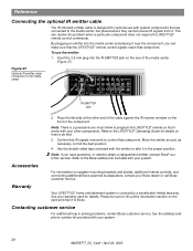
... not respond to Bose. See the address and phone number list provided with your system. 28 AM259777_02_V.pdf • April 23, 2002 To use with system components that are connected to the media center, but placed where they cannot receive IR signals from it to LIFESTYLE® remote control... commands. Figure 27 Optional IR emitter cable connection to ...
... not respond to Bose. See the address and phone number list provided with your system. 28 AM259777_02_V.pdf • April 23, 2002 To use with system components that are connected to the media center, but placed where they cannot receive IR signals from it to LIFESTYLE® remote control... commands. Figure 27 Optional IR emitter cable connection to ...


