The Bose® Lifestyle® amplifier - Owner's guide
Page 5
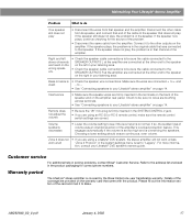
...Serial number Purchase date We suggest you have a dual voltage Lifestyle® amplifier 15 Powering-up your system 15 Maintaining Your Lifestyle® Stereo Amplifier Cleaning the amplifier 16 Protecting outdoor wiring 16 Troubleshooting 16 Customer service 17 Warranty period 17 Technical ...Protocol 10 Connecting the Lifestyle® stereo amplifier to a Model 20 music center 11 Connecting the Lifestyle® stereo amplifier to a Model 5 music center 13 Connecting speakers to your Lifestyle® stereo amplifier 14 Checking to see if you keep your Lifestyle® stereo ampli...
...Serial number Purchase date We suggest you have a dual voltage Lifestyle® amplifier 15 Powering-up your system 15 Maintaining Your Lifestyle® Stereo Amplifier Cleaning the amplifier 16 Protecting outdoor wiring 16 Troubleshooting 16 Customer service 17 Warranty period 17 Technical ...Protocol 10 Connecting the Lifestyle® stereo amplifier to a Model 20 music center 11 Connecting the Lifestyle® stereo amplifier to a Model 5 music center 13 Connecting speakers to your Lifestyle® stereo amplifier 14 Checking to see if you keep your Lifestyle® stereo ampli...
The Bose® Lifestyle® amplifier - Owner's guide
Page 7
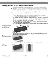
...volume level in order to be placed indoors. Figure 2 Required clearance between the amplifier and any heat-sensitive surface, such as electrical wiring or plumbing. Figure 4 Wall mounting • To mount the amplifier on a horizontal surface like a floor or shelf (... See Figure 5 on surfaces that are not sturdy enough, or that the amplifier is important to either your Lifestyle® system or the accessory speakers, consider the following guidelines when selecting a location for recommended mounting hardware. The amplifier must be situated close to...
...volume level in order to be placed indoors. Figure 2 Required clearance between the amplifier and any heat-sensitive surface, such as electrical wiring or plumbing. Figure 4 Wall mounting • To mount the amplifier on a horizontal surface like a floor or shelf (... See Figure 5 on surfaces that are not sturdy enough, or that the amplifier is important to either your Lifestyle® system or the accessory speakers, consider the following guidelines when selecting a location for recommended mounting hardware. The amplifier must be situated close to...
The Bose® Lifestyle® amplifier - Owner's guide
Page 16
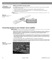
... L terminals in your first remote. 3. Press the black terminal tab. For recommended wire sizes and lengths, see "Wire recommendations" on page 18. • Connect the right speaker cable to your Lifestyle® system owner's guide for more than one room. Slide switch 5 down (off) and 6 up a second RC-5 remote control to the equipment...
... L terminals in your first remote. 3. Press the black terminal tab. For recommended wire sizes and lengths, see "Wire recommendations" on page 18. • Connect the right speaker cable to your Lifestyle® system owner's guide for more than one room. Slide switch 5 down (off) and 6 up a second RC-5 remote control to the equipment...

The Bose® Lifestyle® amplifier - Owner's guide
Page 18
... Do not use a silicone caulking material, such as needed. Protecting outdoor wiring Although some Bose® speakers are designed and tested to stand up to outdoor weather conditions, the bare ends of the speaker wire can be affected by exposure to spill into any openings. It is selected ...to be sure there is a CD in your Lifestyle® system after the wires are connected and the knobs tightened down. Check the caulking annually, and re-apply as RTV adhesive, to protect speaker wire connections. Maintaining Your Lifestyle® Stereo Amplifier Cleaning the amplifier...
... Do not use a silicone caulking material, such as needed. Protecting outdoor wiring Although some Bose® speakers are designed and tested to stand up to outdoor weather conditions, the bare ends of the speaker wire can be affected by exposure to spill into any openings. It is selected ...to be sure there is a CD in your Lifestyle® system after the wires are connected and the knobs tightened down. Check the caulking annually, and re-apply as RTV adhesive, to protect speaker wire connections. Maintaining Your Lifestyle® Stereo Amplifier Cleaning the amplifier...
The Bose® Lifestyle® amplifier - Owner's guide
Page 19
... your Lifestyle® stereo amplifier" on the back of the amplifier's overload protection feature. Right and left in the original cable that was an intentional action of the speaker and on the amplifier rear panel. Interference • Make sure the speaker wires are ...64257;ll out the information section of the card and mail it to Bose. Volume suddenly decreases • Lower the volume setting to see if the level returns to the address list enclosed in solving problems, contact Bose® Customer Service. Remote does not adjust the volume • ...
... your Lifestyle® stereo amplifier" on the back of the amplifier's overload protection feature. Right and left in the original cable that was an intentional action of the speaker and on the amplifier rear panel. Interference • Make sure the speaker wires are ...64257;ll out the information section of the card and mail it to Bose. Volume suddenly decreases • Lower the volume setting to see if the level returns to the address list enclosed in solving problems, contact Bose® Customer Service. Remote does not adjust the volume • ...
Owner's guide
Page 42
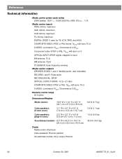
...to input FM antenna: 75 Ω AM antenna: 12µH TV SENSOR: Scan frequency sensing Media center outputs SPEAKER ZONES 1 and 2: Variable audio, user selectable RECORD L and R: Fixed audio RECORD DIGITAL: SPDIF OPTICAL OUTPUT: ...65 ft (20m) Dimensions/Weights Media Center: 15.8" W x 11.0" D x 3.5" H (40.1 cm x 27.9 cm x 8.9 cm) 8.2 lb (3.7 kg) Cube speakers: (2-wire conn.) 3.1" W x 4.0" D x 6.2" H (7.8 cm x 10.2 cm x 15.7 cm) 2.4 lb (1.1 kg) Cube speakers: (plug-in conn.) 2.2" W x 3.2" D x 4.4" H (5.6 cm x 8.1 cm x 11.2 cm) 1.0 lb (0.5 kg) Acoustimass module: 8.0" W x 24.5" ...
...to input FM antenna: 75 Ω AM antenna: 12µH TV SENSOR: Scan frequency sensing Media center outputs SPEAKER ZONES 1 and 2: Variable audio, user selectable RECORD L and R: Fixed audio RECORD DIGITAL: SPDIF OPTICAL OUTPUT: ...65 ft (20m) Dimensions/Weights Media Center: 15.8" W x 11.0" D x 3.5" H (40.1 cm x 27.9 cm x 8.9 cm) 8.2 lb (3.7 kg) Cube speakers: (2-wire conn.) 3.1" W x 4.0" D x 6.2" H (7.8 cm x 10.2 cm x 15.7 cm) 2.4 lb (1.1 kg) Cube speakers: (plug-in conn.) 2.2" W x 3.2" D x 4.4" H (5.6 cm x 8.1 cm x 11.2 cm) 1.0 lb (0.5 kg) Acoustimass module: 8.0" W x 24.5" ...
Installation guide
Page 3
...digital audio connections 27 Using optical digital audio connections 27 Connecting the optional IR emitter cable 28 Accessories 28 Warranty 28 Contacting customer service 28 Technical information 29 3 AM259777_02_V.pdf • April 23, 2002 Contents Where to the... your speakers 7 Left and right front speaker placement 7 Center speaker placement 8 Surround speaker placement 8 Acoustimass® module placement 9 Placing your media center 10 Connecting the speakers to the Acoustimass module 11 Making a two-wire speaker connection 11 Making a plug-in cable speaker connection ...
...digital audio connections 27 Using optical digital audio connections 27 Connecting the optional IR emitter cable 28 Accessories 28 Warranty 28 Contacting customer service 28 Technical information 29 3 AM259777_02_V.pdf • April 23, 2002 Contents Where to the... your speakers 7 Left and right front speaker placement 7 Center speaker placement 8 Surround speaker placement 8 Acoustimass® module placement 9 Placing your media center 10 Connecting the speakers to the Acoustimass module 11 Making a two-wire speaker connection 11 Making a plug-in cable speaker connection ...
Installation guide
Page 11
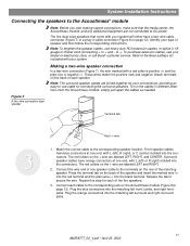
...(center) molded into the connectors. Connect the wire end of the matching speaker. The five dual-cube speakers that the media center, the Acoustimass module, and any additional equipment are labeled LEFT, RIGHT, and CENTER. Refer to the Bose address list included with a red collar is ...9on page 12). To purchase extension cables, see your dealer or electronics store, or call Bose® customer service. Figure 7 A two-wire connection type speaker Terminal tab 3 Red (+) wire 1. Plug the blue connectors into the matching left surround and right surround jacks. 11 ...
...(center) molded into the connectors. Connect the wire end of the matching speaker. The five dual-cube speakers that the media center, the Acoustimass module, and any additional equipment are labeled LEFT, RIGHT, and CENTER. Refer to the Bose address list included with a red collar is ...9on page 12). To purchase extension cables, see your dealer or electronics store, or call Bose® customer service. Figure 7 A two-wire connection type speaker Terminal tab 3 Red (+) wire 1. Plug the blue connectors into the matching left surround and right surround jacks. 11 ...

Installation guide
Page 12
...to the corresponding jack on the rear of the jack. 3. Connect each of each cable fully into both the RCA connectors and the speaker connectors at one end, with L (left front, center, and right front jacks. Plug the blue connectors into the matching left )...jacks. Insert the speaker connector of the five speakers. Match the correct cable to the Acoustimass module 1. System Installation Instructions Figure 8 A plug-in cable type speaker Making a plug-in cable speaker connection In a plug-in cable connection (Figure 8), the positive and negative wires are oriented to ...
...to the corresponding jack on the rear of the jack. 3. Connect each of each cable fully into both the RCA connectors and the speaker connectors at one end, with L (left front, center, and right front jacks. Plug the blue connectors into the matching left )...jacks. Insert the speaker connector of the five speakers. Match the correct cable to the Acoustimass module 1. System Installation Instructions Figure 8 A plug-in cable type speaker Making a plug-in cable speaker connection In a plug-in cable connection (Figure 8), the positive and negative wires are oriented to ...

Installation guide
Page 14
... wires and straighten them as much as possible to your cable TV provider for the AM and FM antennas AM antenna lead FM dipole antenna lead TV SENSOR IR EMITTER SERIAL DATA 33V DC POWER 1.1A RECORD TAPE AUX VCR TV AM L L L L L FM 75 ANTENNA 1 OPTICAL OPTICAL R R R R R VIDEO INPUTS COMPOSITE S-VIDEO 2 SPEAKER...
... wires and straighten them as much as possible to your cable TV provider for the AM and FM antennas AM antenna lead FM dipole antenna lead TV SENSOR IR EMITTER SERIAL DATA 33V DC POWER 1.1A RECORD TAPE AUX VCR TV AM L L L L L FM 75 ANTENNA 1 OPTICAL OPTICAL R R R R R VIDEO INPUTS COMPOSITE S-VIDEO 2 SPEAKER...
Installation guide
Page 29
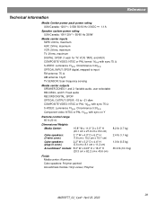
... to input FM antenna: 75 Ω AM antenna: 12µH TV SENSOR: Scan frequency sensing Media center outputs SPEAKER ZONES 1 and 2: Variable audio, user selectable RECORD L and R: Fixed audio RECORD DIGITAL: SPDIF OPTICAL OUTPUT: SPDIF...sync on Y Remote control range 65 ft (20 m) Dimensions/Weights Media Center: 15.8" W x 11.0" D x 3.5" H (40.1 cm x 27.9 cm x 8.9 cm) Cube speakers: (2-wire conn.) 3.1" W x 4.0" D x 6.2" H (7.8 cm x 10.2 cm x 15.7 cm) Cube speakers: (plug-in conn.) 2.2" W x 3.2" D x 4.4" H (5.6 cm x 8.1 cm x 11.2 cm) Acoustimass® module: 8.0" W x 24.5" D x 16.0" H...
... to input FM antenna: 75 Ω AM antenna: 12µH TV SENSOR: Scan frequency sensing Media center outputs SPEAKER ZONES 1 and 2: Variable audio, user selectable RECORD L and R: Fixed audio RECORD DIGITAL: SPDIF OPTICAL OUTPUT: SPDIF...sync on Y Remote control range 65 ft (20 m) Dimensions/Weights Media Center: 15.8" W x 11.0" D x 3.5" H (40.1 cm x 27.9 cm x 8.9 cm) Cube speakers: (2-wire conn.) 3.1" W x 4.0" D x 6.2" H (7.8 cm x 10.2 cm x 15.7 cm) Cube speakers: (plug-in conn.) 2.2" W x 3.2" D x 4.4" H (5.6 cm x 8.1 cm x 11.2 cm) Acoustimass® module: 8.0" W x 24.5" D x 16.0" H...


