The Bose® Lifestyle® amplifier - Owner's guide
Page 15
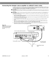
On the rear panel of the Acoustimass® module cable into the red piggyback jack and the white RCA connector into the white piggyback jack. CAUTION: DO NOT connect the audio input cable for the Lifestyle® stereo amplifier to work properly with the fi... speaker outputs 30-ft audio input cable (supplied) Acoustimass module cable AM262840_00_V.pdf January 4, 2002 13 Insert the red RCA piggyback connector of the music center. Figure 12 Cable connections between the Model 5 music center and the Lifestyle® stereo amplifier Model 5 music center...
On the rear panel of the Acoustimass® module cable into the red piggyback jack and the white RCA connector into the white piggyback jack. CAUTION: DO NOT connect the audio input cable for the Lifestyle® stereo amplifier to work properly with the fi... speaker outputs 30-ft audio input cable (supplied) Acoustimass module cable AM262840_00_V.pdf January 4, 2002 13 Insert the red RCA piggyback connector of the music center. Figure 12 Cable connections between the Model 5 music center and the Lifestyle® stereo amplifier Model 5 music center...

The Bose® Lifestyle® amplifier - Owner's guide
Page 18
Do not allow liquids to spill into the FIXED OUTPUTs on the music center. (Then the speaker output cable to the Acoustimass® module should be connected to the piggyback jacks on page 14. 16 January 4, 2002 AM262840_00_V.pdf Do not use any solvents, chemicals, or cleaning ... problem operating your Bose dealer to outdoor weather conditions, the bare ends of the speaker wire can be sure there is especially true of the enclosure. This is a CD in good condition and are firmly connected at hardware stores. If the problem still exists, contact your Lifestyle® system after...
Do not allow liquids to spill into the FIXED OUTPUTs on the music center. (Then the speaker output cable to the Acoustimass® module should be connected to the piggyback jacks on page 14. 16 January 4, 2002 AM262840_00_V.pdf Do not use any solvents, chemicals, or cleaning ... problem operating your Bose dealer to outdoor weather conditions, the bare ends of the speaker wire can be sure there is especially true of the enclosure. This is a CD in good condition and are firmly connected at hardware stores. If the problem still exists, contact your Lifestyle® system after...
Owner's guide
Page 2
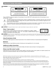
...within an equilateral triangle, as marked on the enclosure of your Acoustimass® module: The lightning flash with the Cirrus Logic integrated circuits ...laser product The DVD player contained within an equilateral triangle, is intended for future reference. ©2001 Bose Corporation. Class B emissions limits This Class B digital apparatus meets all of its advanced features. Manufactured ... Dolby Laboratories. "Dolby" and the double-D symbol are located on the enclosure of your LIFESTYLE® media center and on the system, is limited solely to the presence of important...
...within an equilateral triangle, as marked on the enclosure of your Acoustimass® module: The lightning flash with the Cirrus Logic integrated circuits ...laser product The DVD player contained within an equilateral triangle, is intended for future reference. ©2001 Bose Corporation. Class B emissions limits This Class B digital apparatus meets all of its advanced features. Manufactured ... Dolby Laboratories. "Dolby" and the double-D symbol are located on the enclosure of your LIFESTYLE® media center and on the system, is limited solely to the presence of important...
Owner's guide
Page 31
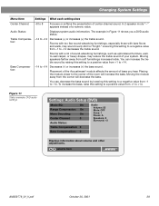
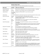
... You can increase the treble sound by lowering this setting to a positive value from the corner will increase the bass. Moving the module away from +1 to +14. Audio Status: Displays system audio information. The example in Figure 11 shows you hear. Rooms with too...: -14 to +14 Decreases (-) or increases (+) the treble sound. selects item AM259776_01_V.pdf October 30, 2001 29 Placement of the Acoustimass® module affects the amount of the room will decrease the bass. Changing System Settings Menu Item Settings What each setting does Center Channel: -8 to...
... You can increase the treble sound by lowering this setting to a positive value from the corner will increase the bass. Moving the module away from +1 to +14. Audio Status: Displays system audio information. The example in Figure 11 shows you hear. Rooms with too...: -14 to +14 Decreases (-) or increases (+) the treble sound. selects item AM259776_01_V.pdf October 30, 2001 29 Placement of the Acoustimass® module affects the amount of the room will decrease the bass. Changing System Settings Menu Item Settings What each setting does Center Channel: -8 to...
Owner's guide
Page 33
...your TV, VCR and AUX components. US Sets channel spacing for all remote control functions. Always use "Normal" for Bose powered speaker systems Acoustimass 5P and Acoustimass 20P. Normal Legacy Provides the correct output (variable level) at the SPEAKER ZONE 2 connector for zone 1. Provides the ...system. This setting may be useful to teach LIFESTYLE® remote commands to the European standard (if available). On IR commands from the other IR remote controls. NTSC PAL Sets video format for the new Acoustimass® module that came with your TV whenever a video ...
...your TV, VCR and AUX components. US Sets channel spacing for all remote control functions. Always use "Normal" for Bose powered speaker systems Acoustimass 5P and Acoustimass 20P. Normal Legacy Provides the correct output (variable level) at the SPEAKER ZONE 2 connector for zone 1. Provides the ...system. This setting may be useful to teach LIFESTYLE® remote commands to the European standard (if available). On IR commands from the other IR remote controls. NTSC PAL Sets video format for the new Acoustimass® module that came with your TV whenever a video ...

Owner's guide
Page 39
... end is firmly seated in the CD tray. • Connect the FM and AM antennas. • Make sure that the power switch on the Acoustimass module is lit on the display. Make sure to select the correct source for the desired input. • Be sure the disc is placed correctly, label...-side up, in the Acoustimass module AUDIO INPUT jack. • Check speaker connections. • Turn the media center off of the back of the remote. This allows the unit to reset...
... end is firmly seated in the CD tray. • Connect the FM and AM antennas. • Make sure that the power switch on the Acoustimass module is lit on the display. Make sure to select the correct source for the desired input. • Be sure the disc is placed correctly, label...-side up, in the Acoustimass module AUDIO INPUT jack. • Check speaker connections. • Turn the media center off of the back of the remote. This allows the unit to reset...
Owner's guide
Page 42
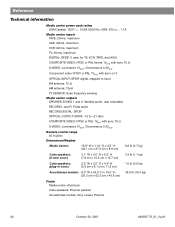
... x 8.9 cm) 8.2 lb (3.7 kg) Cube speakers: (2-wire conn.) 3.1" W x 4.0" D x 6.2" H (7.8 cm x 10.2 cm x 15.7 cm) 2.4 lb (1.1 kg) Cube speakers: (plug-in conn.) 2.2" W x 3.2" D x 4.4" H (5.6 cm x 8.1 cm x 11.2 cm) 1.0 lb (0.5 kg) Acoustimass module: 8.0" W x 24.5" D x 16.0" H 35.9 lb (16.3 kg) (20.3 cm x 62.2 cm x 40.6 cm) Finish Media center: Aluminum Cube speakers: Polymer painted...
... x 8.9 cm) 8.2 lb (3.7 kg) Cube speakers: (2-wire conn.) 3.1" W x 4.0" D x 6.2" H (7.8 cm x 10.2 cm x 15.7 cm) 2.4 lb (1.1 kg) Cube speakers: (plug-in conn.) 2.2" W x 3.2" D x 4.4" H (5.6 cm x 8.1 cm x 11.2 cm) 1.0 lb (0.5 kg) Acoustimass module: 8.0" W x 24.5" D x 16.0" H 35.9 lb (16.3 kg) (20.3 cm x 62.2 cm x 40.6 cm) Finish Media center: Aluminum Cube speakers: Polymer painted...
Installation guide
Page 2
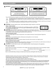
...QUALIFIED PERSONNEL. These CAUTION marks are located on your LIFESTYLE® media center and Acoustimass® module enclosures: The lightning flash with the Cirrus Logic integrated circuits incorporated in this guide. ©2002 Bose Corporation. Class 1 laser product The DVD player contained...Please dispose of used without prior written permission. Do not incinerate. Media center serial number Acoustimass module serial number Dealer name Dealer phone Purchase date Bose® recommends that may be of sufficient magnitude to the presence of important operating...
...QUALIFIED PERSONNEL. These CAUTION marks are located on your LIFESTYLE® media center and Acoustimass® module enclosures: The lightning flash with the Cirrus Logic integrated circuits incorporated in this guide. ©2002 Bose Corporation. Class 1 laser product The DVD player contained...Please dispose of used without prior written permission. Do not incinerate. Media center serial number Acoustimass module serial number Dealer name Dealer phone Purchase date Bose® recommends that may be of sufficient magnitude to the presence of important operating...
Installation guide
Page 3
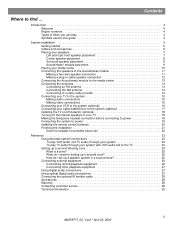
... 6 Placing your speakers 7 Left and right front speaker placement 7 Center speaker placement 8 Surround speaker placement 8 Acoustimass® module placement 9 Placing your media center 10 Connecting the speakers to the Acoustimass module 11 Making a two-wire speaker connection 11 Making a plug-in cable speaker connection 12 Connecting the... audio connections 27 Using optical digital audio connections 27 Connecting the optional IR emitter cable 28 Accessories 28 Warranty 28 Contacting customer service 28 Technical information 29 3 AM259777_02_V.pdf • April 23, 2002
... 6 Placing your speakers 7 Left and right front speaker placement 7 Center speaker placement 8 Surround speaker placement 8 Acoustimass® module placement 9 Placing your media center 10 Connecting the speakers to the Acoustimass module 11 Making a two-wire speaker connection 11 Making a plug-in cable speaker connection 12 Connecting the... audio connections 27 Using optical digital audio connections 27 Connecting the optional IR emitter cable 28 Accessories 28 Warranty 28 Contacting customer service 28 Technical information 29 3 AM259777_02_V.pdf • April 23, 2002
Installation guide
Page 5
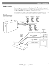
... you how to the Bose address list included with your system if necessary. The instructions in Figure 1. For alternate system connections, see "Using alternate system connections" on page 23. Left front speaker Center front Right front speaker speaker Acoustimass® module Front speaker outputs Rear... system, save all packing materials. System Installation Getting started Figure 1 System connection diagram After unpacking your authorized Bose® dealer immediately, or contact Bose directly. The original packing materials provide the safest way to transport your system.
... you how to the Bose address list included with your system if necessary. The instructions in Figure 1. For alternate system connections, see "Using alternate system connections" on page 23. Left front speaker Center front Right front speaker speaker Acoustimass® module Front speaker outputs Rear... system, save all packing materials. System Installation Getting started Figure 1 System connection diagram After unpacking your authorized Bose® dealer immediately, or contact Bose directly. The original packing materials provide the safest way to transport your system.

Installation guide
Page 6
... antenna Optional IR emitter cable Discs 1 & 2 Media center power supply Headset for custom equalization process Media center power supply 120 VAC power cord (US/Canada) Acoustimass module 120 VAC power cord (US/Canada) 6 AM259777_02_V.pdf • April 23, 2002 System Installation Instructions Cables and accessories The following items are included with your...
... antenna Optional IR emitter cable Discs 1 & 2 Media center power supply Headset for custom equalization process Media center power supply 120 VAC power cord (US/Canada) Acoustimass module 120 VAC power cord (US/Canada) 6 AM259777_02_V.pdf • April 23, 2002 System Installation Instructions Cables and accessories The following items are included with your...

Installation guide
Page 7
...; customer service. Figure 3 Recommended speaker locations Left surround Left front Center Right front Right surround 7 AM259777_02_V.pdf • April 23, 2002 Bose recommends a maximum distance of 3 feet (1 m) from the edge of the TV screen so that the sound does not become too separated from...most pleasing to the Bose address list included with your system. Direct the other cube toward the wall or in Figure 4 on page 8. If you are placing the center speaker on top of each speaker array forward. You may wish to 20 feet (6.1 m) from the Acoustimass® module. • Direct...
...; customer service. Figure 3 Recommended speaker locations Left surround Left front Center Right front Right surround 7 AM259777_02_V.pdf • April 23, 2002 Bose recommends a maximum distance of 3 feet (1 m) from the edge of the TV screen so that the sound does not become too separated from...most pleasing to the Bose address list included with your system. Direct the other cube toward the wall or in Figure 4 on page 8. If you are placing the center speaker on top of each speaker array forward. You may wish to 20 feet (6.1 m) from the Acoustimass® module. • Direct...
Installation guide
Page 8
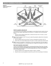
System Installation Instructions Figure 4 Speaker placement and reflection rays Left front Center Right front Acoustimass® module Left surround Right surround Center speaker placement The sound from the center speaker should appear to come directly from the center of....pdf • April 23, 2002 The surround cables allow up to 50 feet (15.2 m) distance from the Acoustimass module. 1. The center speaker cable allows up to 20 feet (6.1 m) distance from the Acoustimass module. 1. Note: If it will sit directly on the TV, be sure to the front and back of the sound...
System Installation Instructions Figure 4 Speaker placement and reflection rays Left front Center Right front Acoustimass® module Left surround Right surround Center speaker placement The sound from the center speaker should appear to come directly from the center of....pdf • April 23, 2002 The surround cables allow up to 50 feet (15.2 m) distance from the Acoustimass module. 1. The center speaker cable allows up to 20 feet (6.1 m) distance from the Acoustimass module. 1. Note: If it will sit directly on the TV, be sure to the front and back of the sound...
Installation guide
Page 9
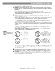
... bottom surface. DO NOT stand the module on the long edge, with the Bose® emblem faces into the room or along the same wall as the TV, or close to the same end of the Acoustimass module. However, you have selected a position for the module, place the four self-adhesive rubber... feet near the Acoustimass module. 9 AM259777_02_V.pdf • April ...
... bottom surface. DO NOT stand the module on the long edge, with the Bose® emblem faces into the room or along the same wall as the TV, or close to the same end of the Acoustimass module. However, you have selected a position for the module, place the four self-adhesive rubber... feet near the Acoustimass module. 9 AM259777_02_V.pdf • April ...
Installation guide
Page 10
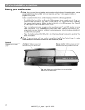
...door. See Figure 6 for easy cable connections. If you allow for a description of the front of your components, see your dealer or call Bose® customer service. Make sure you have enough room to lift up the front cover and open for the media center, keeping in the ... position the media center so that number onto your system. Disc tray - Select a location for you can clearly view the display window to the Bose address list included with your system. • Place the media center within 30 feet (9.1 m) of the Acoustimass® module (the length of the media center.
...door. See Figure 6 for easy cable connections. If you allow for a description of the front of your components, see your dealer or call Bose® customer service. Make sure you have enough room to lift up the front cover and open for the media center, keeping in the ... position the media center so that number onto your system. Disc tray - Select a location for you can clearly view the display window to the Bose address list included with your system. • Place the media center within 30 feet (9.1 m) of the Acoustimass® module (the length of the media center.
Installation guide
Page 11
...cord (connecting + to + and - The five dual-cube speakers that the media center, the Acoustimass module, and any additional equipment are joined together for each cable to the Bose address list included with L (left front, center, and right front jacks. Refer to the corresponding jack... on the Acoustimass module (Figure 9on page 12). Identify your dealer or electronics store, or call Bose® customer service. Note: The ...
...cord (connecting + to + and - The five dual-cube speakers that the media center, the Acoustimass module, and any additional equipment are joined together for each cable to the Bose address list included with L (left front, center, and right front jacks. Refer to the corresponding jack... on the Acoustimass module (Figure 9on page 12). Identify your dealer or electronics store, or call Bose® customer service. Note: The ...

Installation guide
Page 12
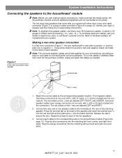
... both the RCA connectors and the speaker connectors at the other end. 2. Plug the orange connectors into the jack on the Acoustimass® module (Figure 9). Match the correct cable to the Acoustimass module 1. Match the ridge of the jack. 3. Plug the blue connectors into both the RCA connectors and the speaker connectors at the...
... both the RCA connectors and the speaker connectors at the other end. 2. Plug the orange connectors into the jack on the Acoustimass® module (Figure 9). Match the correct cable to the Acoustimass module 1. Match the ridge of the jack. 3. Plug the blue connectors into both the RCA connectors and the speaker connectors at the...

Installation guide
Page 13
... place. When properly connected, it should lock in place. When disconnecting the cable from the Acoustimass module, be sure to the Acoustimass module. Figure 10 Acoustimass module connection to media center TV SENSOR IR EMITTER SERIAL DATA 33V DC POWER 1.1A RECORD TAPE AUX...R VIDEO INPUTS COMPOSITE S-VIDEO 2 SPEAKER ZONES INPUT OUTPUT DIGITAL AUDIO OUTPUTS DIGITAL DIGITAL DIGITAL AUDIO INPUTS DIGITAL COMPOSITE S-VIDEO VIDEO OUTPUTS Acoustimass module connector panel AUDIO INPUT OUTPUTS TO CUBE SPEAKERS FRONT SURROUND L C L R R POWER 100-120/200-240V AC 50/60 Hz...
... place. When properly connected, it should lock in place. When disconnecting the cable from the Acoustimass module, be sure to the Acoustimass module. Figure 10 Acoustimass module connection to media center TV SENSOR IR EMITTER SERIAL DATA 33V DC POWER 1.1A RECORD TAPE AUX...R VIDEO INPUTS COMPOSITE S-VIDEO 2 SPEAKER ZONES INPUT OUTPUT DIGITAL AUDIO OUTPUTS DIGITAL DIGITAL DIGITAL AUDIO INPUTS DIGITAL COMPOSITE S-VIDEO VIDEO OUTPUTS Acoustimass module connector panel AUDIO INPUT OUTPUTS TO CUBE SPEAKERS FRONT SURROUND L C L R R POWER 100-120/200-240V AC 50/60 Hz...

Installation guide
Page 14
..., consult a qualified installer. Place the antenna as possible to unwrap the bundled antenna wires and straighten them as much as far from the Acoustimass® module. Connecting to a cable radio provider Some cable TV providers make FM radio signals available through the cable service to this service, contact your home...
..., consult a qualified installer. Place the antenna as possible to unwrap the bundled antenna wires and straighten them as much as far from the Acoustimass® module. Connecting to a cable radio provider Some cable TV providers make FM radio signals available through the cable service to this service, contact your home...

Installation guide
Page 19
... 18). Figure 17 Headset connection for "Finishing the installation" on the connector panel of the Acoustimass® module power cord into an AC (mains) outlet. 2. Plug the other end of the Acoustimass module Connector panel AUDIO INPUT L C R FRONT Power switch OUTPUTS TO CUBE SPEAKERS SURROUND L R POWER 100-120/200-240V AC 50/60 Hz...
... 18). Figure 17 Headset connection for "Finishing the installation" on the connector panel of the Acoustimass® module power cord into an AC (mains) outlet. 2. Plug the other end of the Acoustimass module Connector panel AUDIO INPUT L C R FRONT Power switch OUTPUTS TO CUBE SPEAKERS SURROUND L R POWER 100-120/200-240V AC 50/60 Hz...


