The Bose® Lifestyle® amplifier - Owner's guide
Page 3
... components before cleaning. 7. Servicing is used, use attachments/accessories specified by the manufacturer. 12. Do not attempt to dangerous voltages or other . Keep these instructions - Follow all warnings - ... apparatus has been damaged in accordance with its ventilation openings. 8. Please call Bose to qualified service personnel. as a bookcase or a cabinet that may keep ... plug has two blades with them may expose you . 15. Plug the product into a proper power source, as directed by the manufacturer or sold with a dry cloth - A groundingtype plug has ...
... components before cleaning. 7. Servicing is used, use attachments/accessories specified by the manufacturer. 12. Do not attempt to dangerous voltages or other . Keep these instructions - Follow all warnings - ... apparatus has been damaged in accordance with its ventilation openings. 8. Please call Bose to qualified service personnel. as a bookcase or a cabinet that may keep ... plug has two blades with them may expose you . 15. Plug the product into a proper power source, as directed by the manufacturer or sold with a dry cloth - A groundingtype plug has ...
The Bose® Lifestyle® amplifier - Owner's guide
Page 4
... Code, ANSI/NFPA 70. In particular, it specifies that generate electrical noise If applicable, this is practical. ©2001 Bose Corporation, The Mountain, Framingham, MA 01701-9168 USA 255805 AM Rev.00 JN10494 2b January 10, 2002 AM262840_00_V.pdf If an external ...proper grounding. Ground clamp Electric service equipment Antenna discharge unit (NEC Section 810-20) Grounding conductors (NEC Section 810-21) Ground clamps Power service grounding electrode system (NEC ART 250, Part H) Note to CATV system installer This reminder is provided to call the CATV system installer...
... Code, ANSI/NFPA 70. In particular, it specifies that generate electrical noise If applicable, this is practical. ©2001 Bose Corporation, The Mountain, Framingham, MA 01701-9168 USA 255805 AM Rev.00 JN10494 2b January 10, 2002 AM262840_00_V.pdf If an external ...proper grounding. Ground clamp Electric service equipment Antenna discharge unit (NEC Section 810-20) Grounding conductors (NEC Section 810-21) Ground clamps Power service grounding electrode system (NEC ART 250, Part H) Note to CATV system installer This reminder is provided to call the CATV system installer...
The Bose® Lifestyle® amplifier - Owner's guide
Page 5
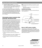
AM262840_00_V.pdf January 4, 2002 3 Serial number Purchase date We suggest you have a dual voltage Lifestyle® amplifier 15 Powering-up your system 15 Maintaining Your Lifestyle® Stereo Amplifier Cleaning the amplifier 16 Protecting outdoor wiring 16 Troubleshooting 16 Customer service 17 Warranty period 17 Technical information 18 For your records ...
AM262840_00_V.pdf January 4, 2002 3 Serial number Purchase date We suggest you have a dual voltage Lifestyle® amplifier 15 Powering-up your system 15 Maintaining Your Lifestyle® Stereo Amplifier Cleaning the amplifier 16 Protecting outdoor wiring 16 Troubleshooting 16 Customer service 17 Warranty period 17 Technical information 18 For your records ...
The Bose® Lifestyle® amplifier - Owner's guide
Page 6
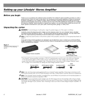
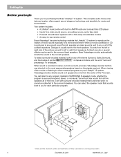
...a simple solution when you want to add Bose® non-powered environmental speakers or Bose non-powered accessory speakers to transport this product. By using the Lifestyle® stereo amplifier to see if you have a dual voltage Lifestyle® ampli- fier" on page... plug adaptor Note: Use only the power cord supplied with Bose non-powered environmental speakers or Bose non-powered accessory speakers ONLY. The original packing materials provide the safest way to your Lifestyle® system. If the power cord does not fit your power (mains) outlet, DO NOT alter the...
...a simple solution when you want to add Bose® non-powered environmental speakers or Bose non-powered accessory speakers to transport this product. By using the Lifestyle® stereo amplifier to see if you have a dual voltage Lifestyle® ampli- fier" on page... plug adaptor Note: Use only the power cord supplied with Bose non-powered environmental speakers or Bose non-powered accessory speakers ONLY. The original packing materials provide the safest way to your Lifestyle® system. If the power cord does not fit your power (mains) outlet, DO NOT alter the...
The Bose® Lifestyle® amplifier - Owner's guide
Page 7
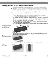
...amplifier on surfaces that are not sturdy enough, or that the amplifier is located within 8 feet (2.5 m) of a power outlet. • Make sure that have hazards concealed behind them, such as the finished surface of fine furniture. CAUTION: DO...Horizontal surface mounting 2.0 in. (5.0 cm) 2.0 in the amplifier's enclosure. The amplifier must be situated close to either your Lifestyle® system or the accessory speakers, consider the following guidelines. Figure 2 Required clearance between the amplifier and any heat-sensitive surface, such ...
...amplifier on surfaces that are not sturdy enough, or that the amplifier is located within 8 feet (2.5 m) of a power outlet. • Make sure that have hazards concealed behind them, such as the finished surface of fine furniture. CAUTION: DO...Horizontal surface mounting 2.0 in. (5.0 cm) 2.0 in the amplifier's enclosure. The amplifier must be situated close to either your Lifestyle® system or the accessory speakers, consider the following guidelines. Figure 2 Required clearance between the amplifier and any heat-sensitive surface, such ...
The Bose® Lifestyle® amplifier - Owner's guide
Page 9
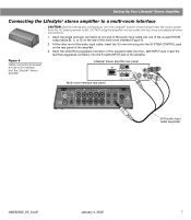
...cable into the L (left) INPUT jack. At the other connections. 1. Figure 6 Cable connections between a multi-room interface and the Lifestyle® stereo amplifier Lifestyle® stereo amplifier rear panel Multi-room interface rear panel 4 Ω MINIMUM LL R L SYSTEM RR CONTROL L R ... amplifier. 3. Insert the white RCA piggyback connector of the multi-room interface (Figure 6). 2. Setting Up Your Lifestyle® Stereo Amplifier Connecting the Lifestyle® stereo amplifier to a multi-room interface CAUTION: Before making any connections, turn the...
...cable into the L (left) INPUT jack. At the other connections. 1. Figure 6 Cable connections between a multi-room interface and the Lifestyle® stereo amplifier Lifestyle® stereo amplifier rear panel Multi-room interface rear panel 4 Ω MINIMUM LL R L SYSTEM RR CONTROL L R ... amplifier. 3. Insert the white RCA piggyback connector of the multi-room interface (Figure 6). 2. Setting Up Your Lifestyle® Stereo Amplifier Connecting the Lifestyle® stereo amplifier to a multi-room interface CAUTION: Before making any connections, turn the...
The Bose® Lifestyle® amplifier - Owner's guide
Page 10
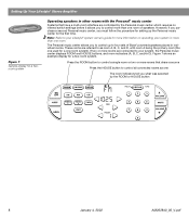
... a one-room system). The Personal music center allows you to control up the Personal music center for the first time. Note: Refer to your Lifestyle® system owner's guide for more information on operating your system, the Personal music center displays ROOM and HOUSE buttons, and room indicators (A, B, C, and... no internal switch settings before it allows you must follow the procedure for setting up to your system in more than one room of Bose® powered speakers placed in other rooms with room A being the primary room (the one used for a two-room system.
... a one-room system). The Personal music center allows you to control up the Personal music center for the first time. Note: Refer to your Lifestyle® system owner's guide for more information on operating your system, the Personal music center displays ROOM and HOUSE buttons, and room indicators (A, B, C, and... no internal switch settings before it allows you must follow the procedure for setting up to your system in more than one room of Bose® powered speakers placed in other rooms with room A being the primary room (the one used for a two-room system.
The Bose® Lifestyle® amplifier - Owner's guide
Page 11
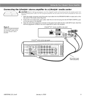
... panel of the amplifier. Setting Up Your Lifestyle® Stereo Amplifier Connecting the Lifestyle® stereo amplifier to a Lifestyle® media center CAUTION: Before making connections, turn the Lifestyle® system off and disconnect the media center from the AC (mains) power outlet. At the other connections. 1. Insert the red RCA...
... panel of the amplifier. Setting Up Your Lifestyle® Stereo Amplifier Connecting the Lifestyle® stereo amplifier to a Lifestyle® media center CAUTION: Before making connections, turn the Lifestyle® system off and disconnect the media center from the AC (mains) power outlet. At the other connections. 1. Insert the red RCA...
The Bose® Lifestyle® amplifier - Owner's guide
Page 13
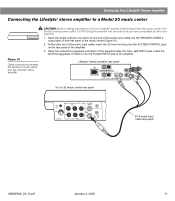
... cable, insert the 3.5 mm mini-plug into the SPEAKER ZONES 2 output jack on the rear panel of the music center (Figure 10). 2. Lifestyle® stereo amplifier rear panel 4 Ω MINIMUM LL R L SYSTEM RR CONTROL L R +- Insert the single multi-pin connector ...Lifestyle® stereo amplifier to a Model 20 music center ® Figure 10 Cable connections between the Model 20 music center and the Lifestyle® stereo amplifier CAUTION: Before making connections, turn the Lifestyle® system off and disconnect the music center from the AC (mains) power...
... cable, insert the 3.5 mm mini-plug into the SPEAKER ZONES 2 output jack on the rear panel of the music center (Figure 10). 2. Lifestyle® stereo amplifier rear panel 4 Ω MINIMUM LL R L SYSTEM RR CONTROL L R +- Insert the single multi-pin connector ...Lifestyle® stereo amplifier to a Model 20 music center ® Figure 10 Cable connections between the Model 20 music center and the Lifestyle® stereo amplifier CAUTION: Before making connections, turn the Lifestyle® system off and disconnect the music center from the AC (mains) power...
The Bose® Lifestyle® amplifier - Owner's guide
Page 15
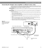
... center, disconnect the audio input cables from the AC (mains) power outlet. Insert the red RCA connector of the music center. Figure 12 Cable connections between the Model 5 music center and the Lifestyle® stereo amplifier Model 5 music center rear panel Lifestyle® stereo amplifier rear panel 4 Ω MINIMUM LL...
... center, disconnect the audio input cables from the AC (mains) power outlet. Insert the red RCA connector of the music center. Figure 12 Cable connections between the Model 5 music center and the Lifestyle® stereo amplifier Model 5 music center rear panel Lifestyle® stereo amplifier rear panel 4 Ω MINIMUM LL...
The Bose® Lifestyle® amplifier - Owner's guide
Page 16
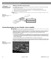
... connected to the equipment. Slide switch 5 down (off) and 6 up a second RC-5 remote control to your Lifestyle® system owner's guide for more information on operating your Lifestyle® stereo amplifier. 1. Speaker cable consists of the amplifier. Figure 14 Speaker cable connections on...(+) terminal into the black jack and release the tab. • Connect the left in your Lifestyle® stereo amplifier CAUTION: DO NOT connect the amplifier to powered speakers of any amplified music sources. Doing so may cause damage to the L output...
... connected to the equipment. Slide switch 5 down (off) and 6 up a second RC-5 remote control to your Lifestyle® system owner's guide for more information on operating your Lifestyle® stereo amplifier. 1. Speaker cable consists of the amplifier. Figure 14 Speaker cable connections on...(+) terminal into the black jack and release the tab. • Connect the left in your Lifestyle® stereo amplifier CAUTION: DO NOT connect the amplifier to powered speakers of any amplified music sources. Doing so may cause damage to the L output...
The Bose® Lifestyle® amplifier - Owner's guide
Page 17
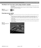
...you plan to connect your amplifier to 115V (North America), slide this switch to see if your Lifestyle® music system to an AC (mains) outlet. 3. Figure 16 Power cord connection on the rear panel of the amplifier. Figure 15 Setting the voltage selection switch to ...the amplifier (Figure 16). 2. Move this switch. • This switch is a power switch on the rear panel (Figure 15). Using the power cord included with your Personal® music center or your Lifestyle® stereo amplifier, firmly insert the small connector on one end of the...
...you plan to connect your amplifier to 115V (North America), slide this switch to see if your Lifestyle® music system to an AC (mains) outlet. 3. Figure 16 Power cord connection on the rear panel of the amplifier. Figure 15 Setting the voltage selection switch to ...the amplifier (Figure 16). 2. Move this switch. • This switch is a power switch on the rear panel (Figure 15). Using the power cord included with your Personal® music center or your Lifestyle® stereo amplifier, firmly insert the small connector on one end of the...
The Bose® Lifestyle® amplifier - Owner's guide
Page 20
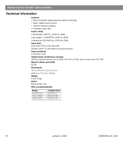
...m) 18 January 4, 2002 AM262840_00_V.pdf W x 51/2 in digital volume control • Thermal overload protection • Protective rubber feet Power rating USA/Canada: 120V 50/60 Hz, 220W Dual voltage: 115/230V 50/60 Hz, 220W International: 220-240V 50/60 Hz...Input sensitivity 0.5 Vrms @ 1 kHz Output power (continuous average) 35W per channel minimum into 4 Ohms, from 30 to Noise ratio (S/N) 90 dB Dimensions 141/4 in . Maintaining Your Lifestyle® Stereo Amplifier Technical information Features • Bose® proprietary digital signal processing technology •...
...m) 18 January 4, 2002 AM262840_00_V.pdf W x 51/2 in digital volume control • Thermal overload protection • Protective rubber feet Power rating USA/Canada: 120V 50/60 Hz, 220W Dual voltage: 115/230V 50/60 Hz, 220W International: 220-240V 50/60 Hz...Input sensitivity 0.5 Vrms @ 1 kHz Output power (continuous average) 35W per channel minimum into 4 Ohms, from 30 to Noise ratio (S/N) 90 dB Dimensions 141/4 in . Maintaining Your Lifestyle® Stereo Amplifier Technical information Features • Bose® proprietary digital signal processing technology •...

Owner's guide
Page 3
... wider blade or third prong are encouraged to try to correct the interference by the manufacturer. 12. Refer all components before cleaning. 7. Do not attempt to dangerous voltages or other apparatus (...the cart/apparatus combination to radio communications. Do not install near any ventilation openings. Protect the power cord from tip-over. 13. Unplug this apparatus during lightning storms or when unused for ... into the apparatus; Please call Bose to be determined by Bose® Corporation. These limits are present. 6. This product complies with the apparatus.
... wider blade or third prong are encouraged to try to correct the interference by the manufacturer. 12. Refer all components before cleaning. 7. Do not attempt to dangerous voltages or other apparatus (...the cart/apparatus combination to radio communications. Do not install near any ventilation openings. Protect the power cord from tip-over. 13. Unplug this apparatus during lightning storms or when unused for ... into the apparatus; Please call Bose to be determined by Bose® Corporation. These limits are present. 6. This product complies with the apparatus.

Owner's guide
Page 4
...-in wire Ground clamp Electric service equipment Antenna discharge unit (NEC Section 810-20) Grounding conductors (NEC Section 810-21) Ground clamps Power service grounding electrode system (NEC ART 250, Part H) Note to CATV system installer This reminder is provided to call the CATV system ... system is practical. Ground all outdoor antennas - This will provide some protection against voltage surges and built-up static charges. Use proper power sources - Section 810 of the National Electrical Code ANSI/ NFPA No. 70 provides information with them may be connected to the grounding...
...-in wire Ground clamp Electric service equipment Antenna discharge unit (NEC Section 810-20) Grounding conductors (NEC Section 810-21) Ground clamps Power service grounding electrode system (NEC ART 250, Part H) Note to CATV system installer This reminder is provided to call the CATV system ... system is practical. Ground all outdoor antennas - This will provide some protection against voltage surges and built-up static charges. Use proper power sources - Section 810 of the National Electrical Code ANSI/ NFPA No. 70 provides information with them may be connected to the grounding...
Owner's guide
Page 6
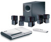
...five speakers all of the available speakers. Even with a hide-away Acoustimass module • An easy-to-use remote control Bose Videostage® decoder technology enables the Lifestyle® 12 system to any or all of the time. When a movie soundtrack or CD is produced in a surround sound format,...AM/FM radio and compact disc (CD) player • Inputs for a video sound source, an auxiliary source, and a tape deck • Powered Acoustimass® speakers with surround-encoded material there are times when no sounds are sent to the surround speakers. You will not hear sound from...
...five speakers all of the available speakers. Even with a hide-away Acoustimass module • An easy-to-use remote control Bose Videostage® decoder technology enables the Lifestyle® 12 system to any or all of the time. When a movie soundtrack or CD is produced in a surround sound format,...AM/FM radio and compact disc (CD) player • Inputs for a video sound source, an auxiliary source, and a tape deck • Powered Acoustimass® speakers with surround-encoded material there are times when no sounds are sent to the surround speakers. You will not hear sound from...
Owner's guide
Page 7
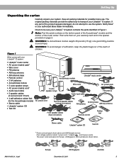
... the reach of the product appears damaged, do not attempt to avoid injury. Dual voltage systems include 1 power cord, 1 adapter , and 2 power packs. Notify Bose® or your Lifestyle® 12 system: • Lifestyle® music center • AC power (mains) pack* • Wire cover • FM antenna • AM loop antenna • AM antenna base •...
... the reach of the product appears damaged, do not attempt to avoid injury. Dual voltage systems include 1 power cord, 1 adapter , and 2 power packs. Notify Bose® or your Lifestyle® 12 system: • Lifestyle® music center • AC power (mains) pack* • Wire cover • FM antenna • AM loop antenna • AM antenna base •...
Owner's guide
Page 10
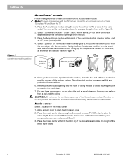
... built-in electronic circuitry, and should not be blocked. Place the music center within reach of the audio input cable, speaker cables, and an AC power (mains) outlet. 4. The slots on the long edge, with the bass and treble controls facing up. Place the Acoustimass module along the same the ... CD player cover. 2. Music center Select a location for the module, place the four self-adhesive rubber feet near the corners of your dealer or call Bose®. 3. An alternate position is on either end, as the TV, or close enough to the sound sources (TV, VCR, etc.) to allow furniture ...
... built-in electronic circuitry, and should not be blocked. Place the music center within reach of the audio input cable, speaker cables, and an AC power (mains) outlet. 4. The slots on the long edge, with the bass and treble controls facing up. Place the Acoustimass module along the same the ... CD player cover. 2. Music center Select a location for the module, place the four self-adhesive rubber feet near the corners of your dealer or call Bose®. 3. An alternate position is on either end, as the TV, or close enough to the sound sources (TV, VCR, etc.) to allow furniture ...
Owner's guide
Page 11
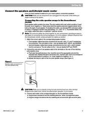
...each terminal tab down, then insert the end of your dealer, electronics store, or call Bose® customer service. Bridged wires create short circuits that affect proper operation of the appropriate... to positive (+ to +) and negative to the terminals on the + wire are unplugged from the power outlet before you have orange connectors at one end, with L, R, and C molded into the connectors... positive (+) and the plain one speaker cable to negative (- Setting Up Connect the speakers and Lifestyle® music center Once you begin hooking up the system. To run the cables in 18...
...each terminal tab down, then insert the end of your dealer, electronics store, or call Bose® customer service. Bridged wires create short circuits that affect proper operation of the appropriate... to positive (+ to +) and negative to the terminals on the + wire are unplugged from the power outlet before you have orange connectors at one end, with L, R, and C molded into the connectors... positive (+) and the plain one speaker cable to negative (- Setting Up Connect the speakers and Lifestyle® music center Once you begin hooking up the system. To run the cables in 18...
Owner's guide
Page 12
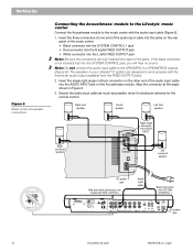
...the rear panel of the audio input cable into SYSTEM CONTROL 1 ® LIFESTYLE ® MODEL 5 MUSIC CENTER B Z G642 950 D S T BOSE Corporation UL LISTED 917D AUDIO ® EQUIPMENT MANUFACTURED: TÜV Rheinland BOSE CORPORATION, FRAMINGHAM, MA 01701-9168 MADE IN USA geprüdfte Sicherheit SPEAKERS... INPUT AM LOOP ANTENNA SYSTEM CONTROL 1 POWER ~ 12VAC IN 1.0A 2 AC power jack 10 December 20, 2001 AM191409_01_V.pdf The speakers in Figure 6. 3. Insert the three connectors at the angle shown in your Lifestyle® 12 system are fully inserted into each of...
...the rear panel of the audio input cable into SYSTEM CONTROL 1 ® LIFESTYLE ® MODEL 5 MUSIC CENTER B Z G642 950 D S T BOSE Corporation UL LISTED 917D AUDIO ® EQUIPMENT MANUFACTURED: TÜV Rheinland BOSE CORPORATION, FRAMINGHAM, MA 01701-9168 MADE IN USA geprüdfte Sicherheit SPEAKERS... INPUT AM LOOP ANTENNA SYSTEM CONTROL 1 POWER ~ 12VAC IN 1.0A 2 AC power jack 10 December 20, 2001 AM191409_01_V.pdf The speakers in Figure 6. 3. Insert the three connectors at the angle shown in your Lifestyle® 12 system are fully inserted into each of...


