Owner's guide
Page 2
... symbol, within the media center is to wide slot, insert fully. The DVD player should not be used only with the PS3-2-1 or PS321 powered speaker system (Acoustimass® module). IL NE SE TROUVE ÀL'INTÉRIEURAUCUNE PIÈCE POUVANT ÊTRE RÉPARÉE PAR L'USAGER. Safety Information... constitute a risk of the media center. Do not incinerate. It will help you set up and operate your owner's guide for future reference. ©2002 Bose Corporation.
... symbol, within the media center is to wide slot, insert fully. The DVD player should not be used only with the PS3-2-1 or PS321 powered speaker system (Acoustimass® module). IL NE SE TROUVE ÀL'INTÉRIEURAUCUNE PIÈCE POUVANT ÊTRE RÉPARÉE PAR L'USAGER. Safety Information... constitute a risk of the media center. Do not incinerate. It will help you set up and operate your owner's guide for future reference. ©2002 Bose Corporation.
Owner's guide
Page 3
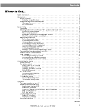
...5 Glossary of terms 5 For your records 7 System Setup 8 Unpacking 8 Selecting locations for your Model 3•2•1 speakers and media center 9 Placing the small speakers 9 Media center placement 10 Placement choices for the Acoustimass® module 11 When the system setup is completed 12 Making the... supplied antennas 17 Connecting cable FM radio 18 Make the power connection after all the others 18 Turning off the internal speakers in your TV 18 Installing remote control batteries 19 Other choices 19 Connecting recording equipment 20 Connecting other playback equipment 21...
...5 Glossary of terms 5 For your records 7 System Setup 8 Unpacking 8 Selecting locations for your Model 3•2•1 speakers and media center 9 Placing the small speakers 9 Media center placement 10 Placement choices for the Acoustimass® module 11 When the system setup is completed 12 Making the... supplied antennas 17 Connecting cable FM radio 18 Make the power connection after all the others 18 Turning off the internal speakers in your TV 18 Installing remote control batteries 19 Other choices 19 Connecting recording equipment 20 Connecting other playback equipment 21...
Owner's guide
Page 4
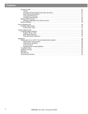
... submenu 36 Parental Control submenu 37 Reference 38 Taking care of your 3•2•1 home entertainment system 38 Cleaning the media center 38 Cleaning the speakers 38 Cleaning discs 38 Replacing the remote batteries 38 Troubleshooting 39 Customer service 40 Warranty 40 Accessories 40 Technical information 40 4 AM256950_02_V.pdf • January...
... submenu 36 Parental Control submenu 37 Reference 38 Taking care of your 3•2•1 home entertainment system 38 Cleaning the media center 38 Cleaning the speakers 38 Cleaning discs 38 Replacing the remote batteries 38 Troubleshooting 39 Customer service 40 Warranty 40 Accessories 40 Technical information 40 4 AM256950_02_V.pdf • January...
Owner's guide
Page 5
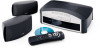
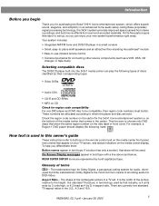
... Your system includes: • Integrated AM/FM tuner and DVD/CD player in a small console • Small, easy-to-place shelf speakers and an attractive floor-standing Acoustimass® module • Easy-to-use infrared remote control • Console input jacks for region code...play the following mark: How text is 4 units wide by 3 units high, or 4:3 (read as 4 by 3) in aspect ratio. Using Bose proprietary signal processing technology, the 3•2•1 system provides improved spaciousness from stereo recordings, and bold movie effects from surround-encoded materials. Check the...
... Your system includes: • Integrated AM/FM tuner and DVD/CD player in a small console • Small, easy-to-place shelf speakers and an attractive floor-standing Acoustimass® module • Easy-to-use infrared remote control • Console input jacks for region code...play the following mark: How text is 4 units wide by 3 units high, or 4:3 (read as 4 by 3) in aspect ratio. Using Bose proprietary signal processing technology, the 3•2•1 system provides improved spaciousness from stereo recordings, and bold movie effects from surround-encoded materials. Check the...
Owner's guide
Page 8
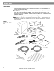
...system includes the parts shown in the space provided on the bottom of children. Check to use it. Notify Bose® or your system. Speakers Rubber feet Rubber feet Acoustimass module Media center Batteries Remote control 120V power cord Antenna stand AM antenna Stereo cable... Video cable Owner's guide Module cable Speaker cable FM antenna Quick setup guide 8 AM256950_02_V.pdf • January 29, 2002 Note: Now is a good time to fi...
...system includes the parts shown in the space provided on the bottom of children. Check to use it. Notify Bose® or your system. Speakers Rubber feet Rubber feet Acoustimass module Media center Batteries Remote control 120V power cord Antenna stand AM antenna Stereo cable... Video cable Owner's guide Module cable Speaker cable FM antenna Quick setup guide 8 AM256950_02_V.pdf • January 29, 2002 Note: Now is a good time to fi...
Owner's guide
Page 9
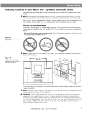
... find other placement variations that your Model 3•2•1 speakers and media center Use the following guidelines to choose locations and positions for the speakers and media center. To contact Bose, refer to the list of offices included in mind that...performance. • If you may obtain additional rubber feet (part number 178321) from Bose® Customer Service. Note: While these speakers farther back in a corner position Note: Angling one or both speakers. Vibration can change the overall quality of sound and alter the movie effects. Figure ...
... find other placement variations that your Model 3•2•1 speakers and media center Use the following guidelines to choose locations and positions for the speakers and media center. To contact Bose, refer to the list of offices included in mind that...performance. • If you may obtain additional rubber feet (part number 178321) from Bose® Customer Service. Note: While these speakers farther back in a corner position Note: Angling one or both speakers. Vibration can change the overall quality of sound and alter the movie effects. Figure ...
Owner's guide
Page 10
... and ordering information, refer to Accessories on their bottom surface (Figure 4). Note: The speakers are designed to sit only on page 40. Bose® recommends a maximum distance of 3 feet from each speaker to the edge of the TV screen to the list of offices included in... it is close enough to additional source components (TV, tape player, VCR) for these connections, contact Bose or your personal preference. • Keep both speakers at approximately the same height. Place the speakers up ), they are needed for all the cables to 3 feet (1 meter) from the edges of...
... and ordering information, refer to Accessories on their bottom surface (Figure 4). Note: The speakers are designed to sit only on page 40. Bose® recommends a maximum distance of 3 feet from each speaker to the edge of the TV screen to the list of offices included in... it is close enough to additional source components (TV, tape player, VCR) for these connections, contact Bose or your personal preference. • Keep both speakers at approximately the same height. Place the speakers up ), they are needed for all the cables to 3 feet (1 meter) from the edges of...
Owner's guide
Page 11
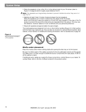
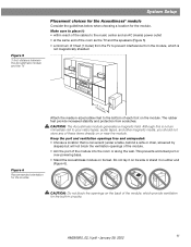
... the cables to the music center and an AC (mains) power outlet • at the same end of the room as the TV and the speakers (Figure 5) • a minimum of 3 feet (1 meter) from the TV to your video tapes, audio tapes, and other magnetic media, you should not store any of...
... the cables to the music center and an AC (mains) power outlet • at the same end of the room as the TV and the speakers (Figure 5) • a minimum of 3 feet (1 meter) from the TV to your video tapes, audio tapes, and other magnetic media, you should not store any of...
Owner's guide
Page 12
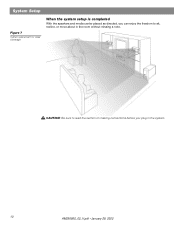
CAUTION: Be sure to read the section on making connections before you can enjoy the freedom to sit, recline, or move about in the system. 12 AM256950_02_V.pdf • January 29, 2002 System Setup Figure 7 System placement for ideal coverage When the system setup is completed With the speakers and media center placed as directed, you plug in the room without missing a note.
CAUTION: Be sure to read the section on making connections before you can enjoy the freedom to sit, recline, or move about in the system. 12 AM256950_02_V.pdf • January 29, 2002 System Setup Figure 7 System placement for ideal coverage When the system setup is completed With the speakers and media center placed as directed, you plug in the room without missing a note.
Owner's guide
Page 13
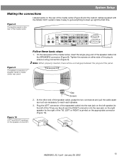
...and the panel. Figure 10 LEFT and RIGHT markings on the appropriate connector (Figure 10). Figure 8 Connection panel on either side of speaker cable to ensure a snug connection (Figure 9). Tighten the screws on the rear of the media center VIDEO 1 D L 75 &#...8486; FM AM LOOP ANTENNA ANTENNA OPTICAL R AUDIO INPUT VIDEO 2 L D R D AUX L VIDEO INPUT C VIDEO OUTPUT C AUDIO OUTPUT L R S S R SPEAKERS ACOUSTIMASS MODULE Figure 9 Completed connection of the plug to media center rear panel Stop/Eject Skip/Scan Source Volume Power Follow these basic steps 1.
...and the panel. Figure 10 LEFT and RIGHT markings on the appropriate connector (Figure 10). Figure 8 Connection panel on either side of speaker cable to ensure a snug connection (Figure 9). Tighten the screws on the rear of the media center VIDEO 1 D L 75 &#...8486; FM AM LOOP ANTENNA ANTENNA OPTICAL R AUDIO INPUT VIDEO 2 L D R D AUX L VIDEO INPUT C VIDEO OUTPUT C AUDIO OUTPUT L R S S R SPEAKERS ACOUSTIMASS MODULE Figure 9 Completed connection of the plug to media center rear panel Stop/Eject Skip/Scan Source Volume Power Follow these basic steps 1.
Owner's guide
Page 14
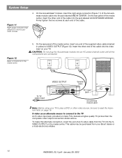
... Insert the other end of the cable into the video input on page 16. RIGHT LEFT To TV video input VIDEO OUTPUT Speaker cable VIDEO D L 75 Ω FM AM LOOP ANTENNA ANTENNA OPTICAL R AUDIO INPUT IDEO 2 L D R D AUX L VIDEO INPUT C VIDEO... OUTPUT C AUDIO OUTPUT L SPEAKERS R S ACOUSTIMASS MODULE S R AC input jack AC INPUT MUSIC CENTER Acoustimass module cable Note: Before using your TV to read the Important Note on your Bose® dealer or a local electronics retailer. 14 AM256950_02_V.pdf • January 29, 2002...
... Insert the other end of the cable into the video input on page 16. RIGHT LEFT To TV video input VIDEO OUTPUT Speaker cable VIDEO D L 75 Ω FM AM LOOP ANTENNA ANTENNA OPTICAL R AUDIO INPUT IDEO 2 L D R D AUX L VIDEO INPUT C VIDEO... OUTPUT C AUDIO OUTPUT L SPEAKERS R S ACOUSTIMASS MODULE S R AC input jack AC INPUT MUSIC CENTER Acoustimass module cable Note: Before using your TV to read the Important Note on your Bose® dealer or a local electronics retailer. 14 AM256950_02_V.pdf • January 29, 2002...
Owner's guide
Page 16
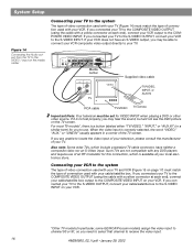
... a composite video nor an S-Video input. VIDEO 1 D L 75 Ω FM AM LOOP ANTENNA ANTENNA OPTICAL R AUDIO INPUT VIDEO 2 L D R D AUX L VIDEO INPUT C VIDEO OUTPUT C AUDIO OUTPUT L SPEAKERS R S ACOUSTIMASS MODULE S R Media center VIDEO IN AUDIO OUT L R TV Supplied video cable TV/VIDEO, INPUT, or AUX IN RCA cable TV/VIDEO TV remote Important...
... a composite video nor an S-Video input. VIDEO 1 D L 75 Ω FM AM LOOP ANTENNA ANTENNA OPTICAL R AUDIO INPUT VIDEO 2 L D R D AUX L VIDEO INPUT C VIDEO OUTPUT C AUDIO OUTPUT L SPEAKERS R S ACOUSTIMASS MODULE S R Media center VIDEO IN AUDIO OUT L R TV Supplied video cable TV/VIDEO, INPUT, or AUX IN RCA cable TV/VIDEO TV remote Important...

Owner's guide
Page 17
...8486; FM AM LOOP ANTENNA ANTENNA OPTICAL R AUDIO INPUT IDEO 2 L D R D AUX L VIDEO INPUT C VIDEO AUDIO OUTPUT OUTPUT C L SPEAKERS R S S R ACOUSTIMASS MODULE FM antenna Plug the connector into the AM antenna jack on the media center. 2. Experiment with positioning the loop for ...Ω AM FM LOOP ANTENNA ANTENNA OPTICAL R AUDIO INPUT VIDEO 2 L D R D AUX L VIDEO INPUT C VIDEO AUDIO OUTPUT OUTPUT C L SPEAKERS R S ACOUSTIMASS MODULE S R Media center VIDEO OUT AUDIO OUT Video cable L R VCR RCA cable Note: Do not connect the video output of ...
...8486; FM AM LOOP ANTENNA ANTENNA OPTICAL R AUDIO INPUT IDEO 2 L D R D AUX L VIDEO INPUT C VIDEO AUDIO OUTPUT OUTPUT C L SPEAKERS R S S R ACOUSTIMASS MODULE FM antenna Plug the connector into the AM antenna jack on the media center. 2. Experiment with positioning the loop for ...Ω AM FM LOOP ANTENNA ANTENNA OPTICAL R AUDIO INPUT VIDEO 2 L D R D AUX L VIDEO INPUT C VIDEO AUDIO OUTPUT OUTPUT C L SPEAKERS R S ACOUSTIMASS MODULE S R Media center VIDEO OUT AUDIO OUT Video cable L R VCR RCA cable Note: Do not connect the video output of ...
Owner's guide
Page 18
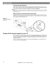
... power (mains) outlet (Figure 17). Make the power connection after all the others To make FM radio signals available through your 3•2•1 system, the speakers in your home. Insert the large end of your cable TV provider for assistance. If your TV does not have an option to turn off... the internal speakers in your TV When you can reduce the volume of the cord into the AC INPUT jack on the module (refer to Figure 12 on...
... power (mains) outlet (Figure 17). Make the power connection after all the others To make FM radio signals available through your 3•2•1 system, the speakers in your home. Insert the large end of your cable TV provider for assistance. If your TV does not have an option to turn off... the internal speakers in your TV When you can reduce the volume of the cord into the AC INPUT jack on the module (refer to Figure 12 on...
Owner's guide
Page 20
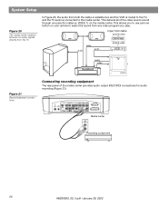
... (Figure 21). This allows you play. VIDEO I D L 75 Ω AM FM LOOP ANTENNA ANTENNA OPTICAL R AUDIO INPUT VIDEO 2 L D AUX L VIDEO INPUT C VIDEO OUTPUT C AUDIO OUTPUT L SPEAKERS R D R S S R ACOUSTIMASS MODULE RECORD INPUT Media center L R Recording component 20 AM256950_02_V.pdf • January 29, 2002 This delivers all audio-for-video signals directly from the...
... (Figure 21). This allows you play. VIDEO I D L 75 Ω AM FM LOOP ANTENNA ANTENNA OPTICAL R AUDIO INPUT VIDEO 2 L D AUX L VIDEO INPUT C VIDEO OUTPUT C AUDIO OUTPUT L SPEAKERS R D R S S R ACOUSTIMASS MODULE RECORD INPUT Media center L R Recording component 20 AM256950_02_V.pdf • January 29, 2002 This delivers all audio-for-video signals directly from the...
Owner's guide
Page 21
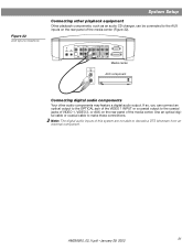
... be connected to make these connections. VIDEO I D L 75 Ω AM FM LOOP ANTENNA ANTENNA OPTICAL R AUDIO INPUT VIDEO 2 L D R D AUX L VIDEO INPUT C VIDEO AUDIO OUTPUT OUTPUT C L R S S R SPEAKERS ACOUSTIMASS MODULE Media center AUDIO OUT AUX component L R Connecting digital audio components Your other playback equipment Other playback components, such as an audio CD changer...
... be connected to make these connections. VIDEO I D L 75 Ω AM FM LOOP ANTENNA ANTENNA OPTICAL R AUDIO INPUT VIDEO 2 L D R D AUX L VIDEO INPUT C VIDEO AUDIO OUTPUT OUTPUT C L R S S R SPEAKERS ACOUSTIMASS MODULE Media center AUDIO OUT AUX component L R Connecting digital audio components Your other playback equipment Other playback components, such as an audio CD changer...
Owner's guide
Page 32
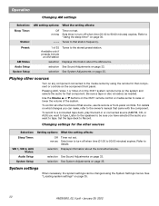
... a connected tape deck, play the built-in or connected source (AM/FM, CD, or AUX) you want to the stored preset station. Listen to the speakers to 90:00 minutes) expires. Set the tape deck to details selection Displays information about the AM source. mm:ss Sets timer to turn off...
... a connected tape deck, play the built-in or connected source (AM/FM, CD, or AUX) you want to the stored preset station. Listen to the speakers to 90:00 minutes) expires. Set the tape deck to details selection Displays information about the AM source. mm:ss Sets timer to turn off...
Owner's guide
Page 33
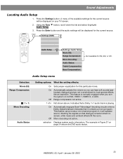
...not active. On Automatically adjusts the volume so you turn the system on page 34 shows the DVD audio status. On Automatically engages Bose® Videostage® decoding circuitry when a Dolby Digital bitstream indicates that dialogue remains locked onscreen, while music and ambient effects fi...settings will be displayed for the current source will be displayed on your TV screen. 2. This feature is playing. The example in multi-speaker sound, directing the signals so that it contains a mono program. AM256950_02_V.pdf • January 29, 2002 33 Press the Settings button....
...not active. On Automatically adjusts the volume so you turn the system on page 34 shows the DVD audio status. On Automatically engages Bose® Videostage® decoding circuitry when a Dolby Digital bitstream indicates that dialogue remains locked onscreen, while music and ambient effects fi...settings will be displayed for the current source will be displayed on your TV screen. 2. This feature is playing. The example in multi-speaker sound, directing the signals so that it contains a mono program. AM256950_02_V.pdf • January 29, 2002 33 Press the Settings button....
Owner's guide
Page 34
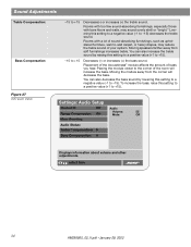
... to +15 Decreases(-) or increases (+) the treble sound. To increase the bass, raise this setting to a negative value (-1 to the corner of your system. Moving speakers farther away from the corner will increase the bass. Placing the module closer to -15) decreases the treble sound. select item 34 AM256950_02_V.pdf •...
... to +15 Decreases(-) or increases (+) the treble sound. To increase the bass, raise this setting to a negative value (-1 to the corner of your system. Moving speakers farther away from the corner will increase the bass. Placing the module closer to -15) decreases the treble sound. select item 34 AM256950_02_V.pdf •...

Owner's guide
Page 38
... require no special care, although you may include cleaning the system's enclosures, cleaning your speakers with a soft, damp cloth. Do not use any sprays near the system. Cleaning the speakers • Clean the surface of your discs, and replacing the remote control batteries. Do not use any solvents,... on a soft cloth to their edges to clean the outside (Figure 28b). Slide the battery compartment cover back into any sprays near the speakers. they can use an ammonia-free window cleaner on or attach labels to the surface of a disc. • To minimize exposure to ...
... require no special care, although you may include cleaning the system's enclosures, cleaning your speakers with a soft, damp cloth. Do not use any sprays near the system. Cleaning the speakers • Clean the surface of your discs, and replacing the remote control batteries. Do not use any solvents,... on a soft cloth to their edges to clean the outside (Figure 28b). Slide the battery compartment cover back into any sprays near the speakers. they can use an ammonia-free window cleaner on or attach labels to the surface of a disc. • To minimize exposure to ...


