Owner's guide
Page 3
... 15 Connecting your TV to the system 16 Connecting your VCR to the system 16 Attaching the supplied antennas 17 Connecting cable FM radio 18 Make the power connection after all the others 18 Turning off the internal speakers in your TV 18 Installing remote control batteries 19 Other ... 20 Connecting other playback equipment 21 Connecting digital audio components 21 Controls, Display, Menus 22 On/Off controls 22 The remote control 22 POWER and MUTE controls 22 SOURCE controls 22 SOURCE and MENU controls 23 PLAYBACK controls 23 The media center 24 Control panel and buttons 24 ...
... 15 Connecting your TV to the system 16 Connecting your VCR to the system 16 Attaching the supplied antennas 17 Connecting cable FM radio 18 Make the power connection after all the others 18 Turning off the internal speakers in your TV 18 Installing remote control batteries 19 Other ... 20 Connecting other playback equipment 21 Connecting digital audio components 21 Controls, Display, Menus 22 On/Off controls 22 The remote control 22 POWER and MUTE controls 22 SOURCE controls 22 SOURCE and MENU controls 23 PLAYBACK controls 23 The media center 24 Control panel and buttons 24 ...
Owner's guide
Page 8
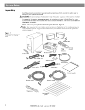
WARNING: To avoid danger of suffocation, keep the plastic bags out of the reach of children. For Bose contact information, refer to transport your system as needed. Save all packing materials, which provide the safest way to the ...center and Acoustimass® module. Speakers Rubber feet Rubber feet Acoustimass module Media center Batteries Remote control 120V power cord Antenna stand AM antenna Stereo cable Video cable Owner's guide Module cable Speaker cable FM antenna Quick setup guide 8 AM256950_02_V.pdf • January 29, 2002 If any part of the system...
WARNING: To avoid danger of suffocation, keep the plastic bags out of the reach of children. For Bose contact information, refer to transport your system as needed. Save all packing materials, which provide the safest way to the ...center and Acoustimass® module. Speakers Rubber feet Rubber feet Acoustimass module Media center Batteries Remote control 120V power cord Antenna stand AM antenna Stereo cable Video cable Owner's guide Module cable Speaker cable FM antenna Quick setup guide 8 AM256950_02_V.pdf • January 29, 2002 If any part of the system...
Owner's guide
Page 11
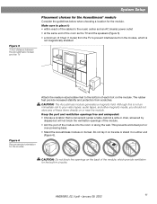
.... • Stand the Acoustimass module on its side or stand it : • within reach of the cables to the music center and an AC (mains) power outlet • at the same end of the room as the TV and the speakers (Figure 5) • a minimum of 3 feet (1 meter) from the TV to ...
.... • Stand the Acoustimass module on its side or stand it : • within reach of the cables to the music center and an AC (mains) power outlet • at the same end of the room as the TV and the speakers (Figure 5) • a minimum of 3 feet (1 meter) from the TV to ...
Owner's guide
Page 13
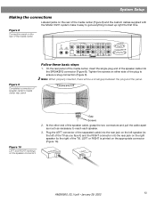
... the speaker connectors Gap Screws 2. Tighten the screws on either side of the plug to media center rear panel Stop/Eject Skip/Scan Source Volume Power Follow these basic steps 1. Figure 8 Connection panel on the rear of the media center VIDEO 1 D L 75 Ω FM AM LOOP ANTENNA ANTENNA OPTICAL...up right the first time. System Setup Making the connections Labeled jacks on the rear of the media center (Figure 8) and the custom cables supplied with the Model 3•2•1 system make it ) and the RIGHT connector into the rear jack on the right speaker (to the ...
... the speaker connectors Gap Screws 2. Tighten the screws on either side of the plug to media center rear panel Stop/Eject Skip/Scan Source Volume Power Follow these basic steps 1. Figure 8 Connection panel on the rear of the media center VIDEO 1 D L 75 Ω FM AM LOOP ANTENNA ANTENNA OPTICAL...up right the first time. System Setup Making the connections Labeled jacks on the rear of the media center (Figure 8) and the custom cables supplied with the Model 3•2•1 system make it ) and the RIGHT connector into the rear jack on the right speaker (to the ...
Owner's guide
Page 14
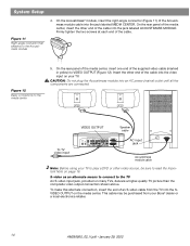
...be purchased from the TV into an AC power (mains) outlet until all the components are connected. S-video as an alternate means to connect to the media center 5. This cable may be sure to play a DVD or other end of an S-video cable from your TV. CAUTION: Do not plug ... the Acoustimass® module, insert the right-angle connector (Figure 11) of the cable into the jack labeled MEDIA CENTER. Figure 12 Basic connections to the TV An S-video input jack, provided on your Bose® dealer or a local electronics retailer. 14 AM256950_02_V.pdf • January 29, 2002 ...
...be purchased from the TV into an AC power (mains) outlet until all the components are connected. S-video as an alternate means to connect to the media center 5. This cable may be sure to play a DVD or other end of an S-video cable from your TV. CAUTION: Do not plug ... the Acoustimass® module, insert the right-angle connector (Figure 11) of the cable into the jack labeled MEDIA CENTER. Figure 12 Basic connections to the TV An S-video input jack, provided on your Bose® dealer or a local electronics retailer. 14 AM256950_02_V.pdf • January 29, 2002 ...
Owner's guide
Page 18
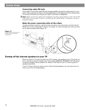
...the AC INPUT jack on the module (refer to your cable TV provider for detailed instructions. Insert the large end of the media center. System Setup Figure 17 Power cord as the final connection Connecting cable FM radio Some cable TV providers make the final connection, insert the... small connector end of the power cord into an AC power (mains) outlet (Figure 17). AC outlet Turning off...
...the AC INPUT jack on the module (refer to your cable TV provider for detailed instructions. Insert the large end of the media center. System Setup Figure 17 Power cord as the final connection Connecting cable FM radio Some cable TV providers make the final connection, insert the... small connector end of the power cord into an AC power (mains) outlet (Figure 17). AC outlet Turning off...
Owner's guide
Page 39
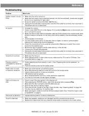
...Check the connections for a minute, then reconnect it is distorted • Adjust antenna position to unmute the sound. • Make sure the module cable and speaker cable are connected properly. • Move AM antenna at the media center. Sound is distorted • Make sure speaker...electronic equipment. • You may be defective. Clean the disc. See "Check for both the DVD and player match. thing • Make sure the power cord is placed correctly, label-side up ). • Eject the disc and try loading it . No sound • Increase the volume. • ...
...Check the connections for a minute, then reconnect it is distorted • Adjust antenna position to unmute the sound. • Make sure the module cable and speaker cable are connected properly. • Move AM antenna at the media center. Sound is distorted • Make sure speaker...electronic equipment. • You may be defective. Clean the disc. See "Check for both the DVD and player match. thing • Make sure the power cord is placed correctly, label-side up ). • Eject the disc and try loading it . No sound • Increase the volume. • ...
Owner's guide
Page 40
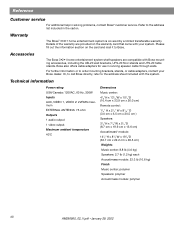
... accessories, including the UB-20 wall brackets, UFS-20 floor stands and UTS-20 table stands. Or, to call Bose directly, refer to Bose. Technical information Power rating USA/Canada: 120VAC, 60 Hz, 300W Inputs AUX, VIDEO 1, VIDEO 2: 2VRMS maximum EXTERNAL ANTENNA: 75 ohm Outputs 1 ...pdf • January 29, 2002 Details of the warranty are compatible with the system. Bose also offers cable adapters for use in the carton. Refer to order mounting brackets, stands, or cable adapters, contact your system. Please fill out the information section on the warranty ...
... accessories, including the UB-20 wall brackets, UFS-20 floor stands and UTS-20 table stands. Or, to call Bose directly, refer to Bose. Technical information Power rating USA/Canada: 120VAC, 60 Hz, 300W Inputs AUX, VIDEO 1, VIDEO 2: 2VRMS maximum EXTERNAL ANTENNA: 75 ohm Outputs 1 ...pdf • January 29, 2002 Details of the warranty are compatible with the system. Bose also offers cable adapters for use in the carton. Refer to order mounting brackets, stands, or cable adapters, contact your system. Please fill out the information section on the warranty ...


