Owner's guide
Page 2
... prevent electric shock, match wide blade of the media center. English Safety Information The AV3-2-1 and AV3-2-1 GS media centers are located on the bottom of your owner's guide for future reference. ©2003 Bose Corporation. REFER SERVICING TO QUALIFIED PERSONNEL. It will help you set up and operate your system properly...
... prevent electric shock, match wide blade of the media center. English Safety Information The AV3-2-1 and AV3-2-1 GS media centers are located on the bottom of your owner's guide for future reference. ©2003 Bose Corporation. REFER SERVICING TO QUALIFIED PERSONNEL. It will help you set up and operate your system properly...

Owner's guide
Page 3
Contents English EEssppaanñooll Francçais Appendix Where to restrict future play 34 Parental Control submenu 34 AM271966_00_V.pdf August 18, 2003 3 Safety Information 2 Contents 3 Before you begin 5 Selecting compatible discs 5 How text is used in this owner's guide 5 Glossary of terms 6 For your records 7 Unpacking 8 Finding the product serial numbers 8 Selecting locations for your 3•2•1 home entertainment system components 9 Placing the media center 9 Placing the 3•2•1 speakers 9 Placing the Acoustimass® module 12 When the system...
Contents English EEssppaanñooll Francçais Appendix Where to restrict future play 34 Parental Control submenu 34 AM271966_00_V.pdf August 18, 2003 3 Safety Information 2 Contents 3 Before you begin 5 Selecting compatible discs 5 How text is used in this owner's guide 5 Glossary of terms 6 For your records 7 Unpacking 8 Finding the product serial numbers 8 Selecting locations for your 3•2•1 home entertainment system components 9 Placing the media center 9 Placing the 3•2•1 speakers 9 Placing the Acoustimass® module 12 When the system...
Owner's guide
Page 4
... menu 40 Locating system settings 42 System Setup menu 43 DVD Setup submenu 43 Reference 44 Taking care of your 3•2•1 or 3•2•1 GS system 44 Cleaning the media center 44 Cleaning the speakers 44 Cleaning discs 44 Replacing the remote batteries 44 Troubleshooting 45 Customer service 46 Warranty...
... menu 40 Locating system settings 42 System Setup menu 43 DVD Setup submenu 43 Reference 44 Taking care of your 3•2•1 or 3•2•1 GS system 44 Cleaning the media center 44 Cleaning the speakers 44 Cleaning discs 44 Replacing the remote batteries 44 Troubleshooting 45 Customer service 46 Warranty...

Owner's guide
Page 5
...region code number on the carton of the 3•2•1 home entertainment system or on the disc label or front cover. Using Bose proprietary signal processing technology, the 3•2•1 systems provide improved spaciousness from stereo recordings, and bold movie effects from surround-encoded...systems, MP3s must meet the following types of the media center that appear on CD Check for purchasing the Bose® 3•2•1 or 3•2•1 GS home entertainment system, which must match. AM271966_00_V.pdf August 18, 2003 5 Yet its additional components) are allocated...
...region code number on the carton of the 3•2•1 home entertainment system or on the disc label or front cover. Using Bose proprietary signal processing technology, the 3•2•1 systems provide improved spaciousness from stereo recordings, and bold movie effects from surround-encoded...systems, MP3s must meet the following types of the media center that appear on CD Check for purchasing the Bose® 3•2•1 or 3•2•1 GS home entertainment system, which must match. AM271966_00_V.pdf August 18, 2003 5 Yet its additional components) are allocated...

Owner's guide
Page 6
The shape of multi-channel surround sound format used on MPEG video, Dolby Digital and MPEG audio, and other limited viewing uses only unless otherwise authorized by Cirrus Logic, Inc. Our standard TV picture, in terminology used by that industry, is protected by 3) in aspect ratio. A single video signal that sends/receives commands on an infrared light beam. a type of the rectangular picture in this copyright protection technology must be authorized by Macrovision Corporation, and is limited solely to the height. the logo representing the above . A standard for ...
The shape of multi-channel surround sound format used on MPEG video, Dolby Digital and MPEG audio, and other limited viewing uses only unless otherwise authorized by Cirrus Logic, Inc. Our standard TV picture, in terminology used by that industry, is protected by 3) in aspect ratio. A single video signal that sends/receives commands on an infrared light beam. a type of the rectangular picture in this copyright protection technology must be authorized by Macrovision Corporation, and is limited solely to the height. the logo representing the above . A standard for ...

Owner's guide
Page 7
... - NTSC - PCM is used for National Television System Committee. English Introduction MPEG - A video interface standard that allows you keep your serial number ready before contacting Bose® customer service. a type of music on a single CD. This is one of several composite video systems. The PAL format is also used for many...
... - NTSC - PCM is used for National Television System Committee. English Introduction MPEG - A video interface standard that allows you keep your serial number ready before contacting Bose® customer service. a type of music on a single CD. This is one of several composite video systems. The PAL format is also used for many...
Owner's guide
Page 8
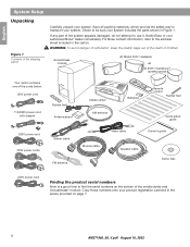
... part of the system appears damaged, do not attempt to find the serial numbers on page 7. 8 AM271966_00_V.pdf August 18, 2003 Notify Bose or your product registration card and in the space provided on the bottom of the cords below: 120V power cord 115/230V power cord with ...cable Demo disc 240V power cord Finding the product serial numbers Now is a good time to use it. Copy those numbers onto your authorized Bose® dealer immediately. Save all packing materials, which provide the safest way to transport your system includes the parts shown in the carton. For...
... part of the system appears damaged, do not attempt to find the serial numbers on page 7. 8 AM271966_00_V.pdf August 18, 2003 Notify Bose or your product registration card and in the space provided on the bottom of the cords below: 120V power cord 115/230V power cord with ...cable Demo disc 240V power cord Finding the product serial numbers Now is a good time to use it. Copy those numbers onto your authorized Bose® dealer immediately. Save all packing materials, which provide the safest way to transport your system includes the parts shown in the carton. For...

Owner's guide
Page 9
The Acoustimass® module is designed to deliver. Placing the media center CAUTION: Do not block any ventilation openings. Do not put the product in mind that all the cables will reach. Note: The speakers are magnetically shielded to prevent interference when they are using a bookshelf or a home entertainment unit, place each speaker at approximately the same height. Positioning the speakers too far back in system, such as a bookcase or cabinet that may keep air from flowing through its ventilation openings. • Place the media center where nothing obstructs opening the ...
The Acoustimass® module is designed to deliver. Placing the media center CAUTION: Do not block any ventilation openings. Do not put the product in mind that all the cables will reach. Note: The speakers are magnetically shielded to prevent interference when they are using a bookshelf or a home entertainment unit, place each speaker at approximately the same height. Positioning the speakers too far back in system, such as a bookcase or cabinet that may keep air from flowing through its ventilation openings. • Place the media center where nothing obstructs opening the ...

Owner's guide
Page 10
... area significantly alters system performance. To contact Bose, refer to the list of of the 3•2•1 and 3•2•1 GS speakers, facing straight ahead toward the listening area. The 3•2•1 and 3•2•1 GS speakers are placing the speakers on a flat ...(Figure 3). Be sure each 3•2•1 or 3•2•1 GS speaker faces straight ahead toward the listening area, not angled WARNING: Choose a stable and level surface for both speakers into or away from Bose® customer service. Vibration can cause the speakers to sit only ...
... area significantly alters system performance. To contact Bose, refer to the list of of the 3•2•1 and 3•2•1 GS speakers, facing straight ahead toward the listening area. The 3•2•1 and 3•2•1 GS speakers are placing the speakers on a flat ...(Figure 3). Be sure each 3•2•1 or 3•2•1 GS speaker faces straight ahead toward the listening area, not angled WARNING: Choose a stable and level surface for both speakers into or away from Bose® customer service. Vibration can cause the speakers to sit only ...

Owner's guide
Page 11
For ordering information, refer to the list of offices included in the product carton. AM271966_00_V.pdf August 18, 2003 11 English Figure 5 Speaker accessories System Setup Speaker Accessories The 3•2•1 and 3•2•1 GS speakers can also be mounted on page 46. UB-20 Wall Bracket UT-S20 Table Stand UFS-20 Floor Stand Additional cables To contact Bose for additional or longer cables, refer to "Accessories" on optional Bose brackets, table stands, or floor stands (Figure 5).
For ordering information, refer to the list of offices included in the product carton. AM271966_00_V.pdf August 18, 2003 11 English Figure 5 Speaker accessories System Setup Speaker Accessories The 3•2•1 and 3•2•1 GS speakers can also be mounted on page 46. UB-20 Wall Bracket UT-S20 Table Stand UFS-20 Floor Stand Additional cables To contact Bose for additional or longer cables, refer to "Accessories" on optional Bose brackets, table stands, or floor stands (Figure 5).

Owner's guide
Page 12
Make sure to place it: • within reach of the cables to the music center and an AC (mains) power outlet • at the same end of the room as the TV and the speakers (Figure 6) • a minimum of the module into the room or along the wall. Although this is convenient (under a table, behind a sofa or chair, screened by drapes) but will not block the ventilation openings of the module. • Aim the port of 3 feet (1 meter) from the TV, to prevent interference from scratches. This prevents a blocked port or over-powering bass. • Stand the Acoustimass module on its side ...
Make sure to place it: • within reach of the cables to the music center and an AC (mains) power outlet • at the same end of the room as the TV and the speakers (Figure 6) • a minimum of the module into the room or along the wall. Although this is convenient (under a table, behind a sofa or chair, screened by drapes) but will not block the ventilation openings of the module. • Aim the port of 3 feet (1 meter) from the TV, to prevent interference from scratches. This prevents a blocked port or over-powering bass. • Stand the Acoustimass module on its side ...

Owner's guide
Page 13
AM271966_00_V.pdf August 18, 2003 13 English System Setup Figure 8 System placement for ideal coverage When the system setup is completed With the speakers and media center placed as directed, you plug in the room without missing a note. CAUTION: Be sure to read the section on making the connections before you can enjoy the freedom to sit, recline, or move about in the system.
AM271966_00_V.pdf August 18, 2003 13 English System Setup Figure 8 System placement for ideal coverage When the system setup is completed With the speakers and media center placed as directed, you plug in the room without missing a note. CAUTION: Be sure to read the section on making the connections before you can enjoy the freedom to sit, recline, or move about in the system.
Owner's guide
Page 14
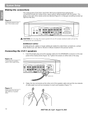
... to help get everything hooked up right the first time. The jacks on the rear of the 3•2•1 and 3•2•1 GS home entertainment systems are connected through the media center, using custom cables supplied with the system. Connecting the 3•2•1 speakers 1. Insert the ...10). Additional cables If additional audio cables or longer cables are connected. Figure 10 Connecting the speaker cable to make these connections, contact Bose. Grasp the two connectors at the other end of the speaker cable and pull the two strands of the plug. Tighten the screws ...
... to help get everything hooked up right the first time. The jacks on the rear of the 3•2•1 and 3•2•1 GS home entertainment systems are connected through the media center, using custom cables supplied with the system. Connecting the 3•2•1 speakers 1. Insert the ...10). Additional cables If additional audio cables or longer cables are connected. Figure 10 Connecting the speaker cable to make these connections, contact Bose. Grasp the two connectors at the other end of the speaker cable and pull the two strands of the plug. Tighten the screws ...

Owner's guide
Page 15
Plug the connector labeled LEFT into the MEDIA CENTER jack. 2. Firmly tighten the two screws at each end of the Acoustimass® module. Insert the other system connections have been made. Place the right speaker to the right of the left speaker (Figure 12). 4. Locate the jack labeled MEDIA CENTER on the rear of the TV as you face it . AM271966_00_V.pdf August 18, 2003 15 Insert the right-angle connector (Figure 14) of the module cable into the jack on the rear of the module cable. English Figure 12 Making the left of the media center. Left and right speaker ...
Plug the connector labeled LEFT into the MEDIA CENTER jack. 2. Firmly tighten the two screws at each end of the Acoustimass® module. Insert the other system connections have been made. Place the right speaker to the right of the left speaker (Figure 12). 4. Locate the jack labeled MEDIA CENTER on the rear of the TV as you face it . AM271966_00_V.pdf August 18, 2003 15 Insert the right-angle connector (Figure 14) of the module cable into the jack on the rear of the module cable. English Figure 12 Making the left of the media center. Left and right speaker ...

Owner's guide
Page 16
English System Setup Attaching the supplied antennas On the rear panel of the two that only the FM radio band, not the cable TV band, is made to establish optimum FM reception. Unwind the wires for each antenna to this service, contact your cable TV provider for optimum AM reception. 3. Spread out the antenna arms at least 4 feet (1.2 meters) from the media center and other end and move them around to the external FM jack on the supplied base, or mount it on the back panel of the media center. If necessary, contact your home. Note: An outdoor antenna may be used in place ...
English System Setup Attaching the supplied antennas On the rear panel of the two that only the FM radio band, not the cable TV band, is made to establish optimum FM reception. Unwind the wires for each antenna to this service, contact your cable TV provider for optimum AM reception. 3. Spread out the antenna arms at least 4 feet (1.2 meters) from the media center and other end and move them around to the external FM jack on the supplied base, or mount it on the back panel of the media center. If necessary, contact your home. Note: An outdoor antenna may be used in place ...

Owner's guide
Page 17
Attach the other end of the stereo cable to the TV by inserting the white plug into the jack labeled VIDEO 1 (L), and the red plug into one of the video input jacks on your TV. See "Selecting the correct video input on the back of the screen to indicate which video input is on, the display "VIDEO 1", "VIDEO 2", or "AUX" will usually appear in order to play a DVD, your television must be using the 3•2•1 home entertainment system with both a TV and a VCR, skip this section and go to "Connecting your TV and VCR to the media center" on your television, please consult your TV...
Attach the other end of the stereo cable to the TV by inserting the white plug into the jack labeled VIDEO 1 (L), and the red plug into one of the video input jacks on your TV. See "Selecting the correct video input on the back of the screen to indicate which video input is on, the display "VIDEO 1", "VIDEO 2", or "AUX" will usually appear in order to play a DVD, your television must be using the 3•2•1 home entertainment system with both a TV and a VCR, skip this section and go to "Connecting your TV and VCR to the media center" on your television, please consult your TV...

Owner's guide
Page 18
... S-video cable from your TV owner's guide for instructions). Turning off the internal speakers in your TV When you must also use S-video to your Bose® dealer or a local electronics retailer. To make this connection, which is available at your TV should not be purchased from the TV into the...
... S-video cable from your TV owner's guide for instructions). Turning off the internal speakers in your TV When you must also use S-video to your Bose® dealer or a local electronics retailer. To make this connection, which is available at your TV should not be purchased from the TV into the...

Owner's guide
Page 19
Attach one of these jacks, make note of the name of the supplied video cable (yellow) to the VIDEO OUTPUT jack on your TV. See "Selecting the correct video input on your TV owner's guide if you need to select the corresponding video input setting on your TV has audio output jacks, you connect the yellow video cable to one end of the jack you choose. Under the AUDIO INPUT heading, there are two options for example: Video 1, Input 1, or Aux). Attach the other end of the video cable (yellow) into one of the video input jacks on the back of the media center. Consult your...
Attach one of these jacks, make note of the name of the supplied video cable (yellow) to the VIDEO OUTPUT jack on your TV. See "Selecting the correct video input on your TV owner's guide if you need to select the corresponding video input setting on your TV has audio output jacks, you connect the yellow video cable to one end of the jack you choose. Under the AUDIO INPUT heading, there are two options for example: Video 1, Input 1, or Aux). Attach the other end of the video cable (yellow) into one of the video input jacks on the back of the media center. Consult your...

Owner's guide
Page 20
When the TV is currently selected. Before playing a DVD, locate the name of the screen to your TV When you have a TV/VIDEO, INPUT, or AUX IN button for instructions). Note: In some models, when the TV's internal speakers are unable to locate the video input setting on your TV to locate the setting for INTERNAL SPEAKERS and select OFF. (Refer to indicate which video input is on the screen) that matches the name of that jack. Most TVs have connected the yellow video cable to hear audio from the correct video input jack. Turning off the internal speakers, you may need to ...
When the TV is currently selected. Before playing a DVD, locate the name of the screen to your TV When you have a TV/VIDEO, INPUT, or AUX IN button for instructions). Note: In some models, when the TV's internal speakers are unable to locate the video input setting on your TV to locate the setting for INTERNAL SPEAKERS and select OFF. (Refer to indicate which video input is on the screen) that matches the name of that jack. Most TVs have connected the yellow video cable to hear audio from the correct video input jack. Turning off the internal speakers, you may need to ...

Owner's guide
Page 21
Attach the stereo cable to the media center by inserting the white plug into the Audio Out (L) jack and the red plug into the Audio Out (R) jack. 6. When you connect the yellow video cable to one end of the stereo cable to the VCR by inserting the white plug into the jack labeled VIDEO 1(L) and the red plug into the Video Output jack on your TV. Attach the other end of the supplied video cable (yellow) into the jack labeled VIDEO 1(R). 5. Attach the other end of the supplied video cable (yellow) to the VIDEO INPUT jack on the back of the media center. 3. See "Selecting the ...
Attach the stereo cable to the media center by inserting the white plug into the Audio Out (L) jack and the red plug into the Audio Out (R) jack. 6. When you connect the yellow video cable to one end of the stereo cable to the VCR by inserting the white plug into the jack labeled VIDEO 1(L) and the red plug into the Video Output jack on your TV. Attach the other end of the supplied video cable (yellow) into the jack labeled VIDEO 1(R). 5. Attach the other end of the supplied video cable (yellow) to the VIDEO INPUT jack on the back of the media center. 3. See "Selecting the ...
