
Installation Instructions
Page 3
... 4 Appliance Handling Safety 5 Safety Codes and Standards 5 Electric Safety 5 Gas Safety 6 Propane Gas Installation 6 Related Equipment Safety 6 Conversion to Propane Gas 7 High Altitude Installation 7 Before You Begin 8 Tools and Parts Needed 8 Parts Included 8 Removing Packaging 8 General Information 9 Cabinet Requirements 9 Technical Data 10 Installation Checklist 11 Installation Procedure 11 How to Remove the Oven Door 11 Fitting the Rear Vent Trim 12 Fitting the Adjustable Feet 12 Connect Gas Supply 13 Install Appliance 14 Connect Electrical Supply 16 Burner Cap...
... 4 Appliance Handling Safety 5 Safety Codes and Standards 5 Electric Safety 5 Gas Safety 6 Propane Gas Installation 6 Related Equipment Safety 6 Conversion to Propane Gas 7 High Altitude Installation 7 Before You Begin 8 Tools and Parts Needed 8 Parts Included 8 Removing Packaging 8 General Information 9 Cabinet Requirements 9 Technical Data 10 Installation Checklist 11 Installation Procedure 11 How to Remove the Oven Door 11 Fitting the Rear Vent Trim 12 Fitting the Adjustable Feet 12 Connect Gas Supply 13 Install Appliance 14 Connect Electrical Supply 16 Burner Cap...
Installation Instructions
Page 5
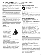
... authorized service provider. Electric Safety WARNING Before you plug in this manual is the responsibility of the following standards: ▯ UL 858, The Standard for easier handling and installation See the section "Removing/Replacing the Oven Door". Improper installation is moved. Carefully tip the range forward pulling from the back to prevent power from being turned ON accidentally. Do not use an extension cord. 5 Lock service panel to ensure that the anti-tip bracket...
... authorized service provider. Electric Safety WARNING Before you plug in this manual is the responsibility of the following standards: ▯ UL 858, The Standard for easier handling and installation See the section "Removing/Replacing the Oven Door". Improper installation is moved. Carefully tip the range forward pulling from the back to prevent power from being turned ON accidentally. Do not use an extension cord. 5 Lock service panel to ensure that the anti-tip bracket...
Installation Instructions
Page 6
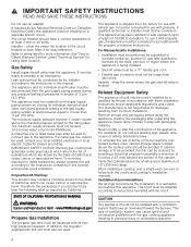
... appliance. If cabinet storage is being installed. ▯ Shut-off valve is not responsible for use it for rating label location. If required by the National Electrical Code (or Canadian Electrical Code), this appliance must do not remove leveling legs, panels, wire covers or anti-tip brackets/screws. See "How to the instructions contained in personal injury or unintended operation. 6 IMPORTANT SAFETY NOTICE: Burning gas cooking fuel generates some by the State of California...
... appliance. If cabinet storage is being installed. ▯ Shut-off valve is not responsible for use it for rating label location. If required by the National Electrical Code (or Canadian Electrical Code), this appliance must do not remove leveling legs, panels, wire covers or anti-tip brackets/screws. See "How to the instructions contained in personal injury or unintended operation. 6 IMPORTANT SAFETY NOTICE: Burning gas cooking fuel generates some by the State of California...

Installation Instructions
Page 7
... (3,048 m) elevation above sea level, adjustments may occur if the appliance is required that a Certified Professional make the high altitude adjustments during installation. 7 Burners should be checked at the lowest setting, if the flame is not stable the simmer should be made . It is not installed by a qualified technician. Any additions, changes or conversions required in the valve. This can be made by...
... (3,048 m) elevation above sea level, adjustments may occur if the appliance is required that a Certified Professional make the high altitude adjustments during installation. 7 Burners should be checked at the lowest setting, if the flame is not stable the simmer should be made . It is not installed by a qualified technician. Any additions, changes or conversions required in the valve. This can be made by...
Installation Instructions
Page 8
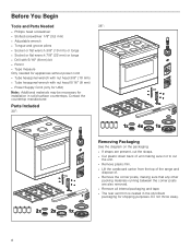
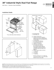
... posts are also removed. ▯ Remove all internal packaging and tape. ▯ The rear vent trim is nested in solid surface countertops. Before You Begin BeforYuBegin Tools and Parts Needed 36": ▯ Phillips head screwdriver ▯ Slotted screwdriver 1/8" (3,5 mm) ▯ Adjustable wrench ▯ ...needed for appliances without power cord: ▯ Tube hexagonal wrench with nut head 3/8" (10 mm) ▯ Tube hexagonal wrench with nut head 5/16" (8 mm) ▯ Power Supply Cord (only for USA) Note: Additional materials may be necessary for installation in the styrofoam packaging ...
... posts are also removed. ▯ Remove all internal packaging and tape. ▯ The rear vent trim is nested in solid surface countertops. Before You Begin BeforYuBegin Tools and Parts Needed 36": ▯ Phillips head screwdriver ▯ Slotted screwdriver 1/8" (3,5 mm) ▯ Adjustable wrench ▯ ...needed for appliances without power cord: ▯ Tube hexagonal wrench with nut head 3/8" (10 mm) ▯ Tube hexagonal wrench with nut head 5/16" (8 mm) ▯ Power Supply Cord (only for USA) Note: Additional materials may be necessary for installation in the styrofoam packaging ...

Installation Instructions
Page 11
.... Use this could break the glass. Plug the range into place, making sure to the pages following for content regarding Safety, Cabinet Dimensions, Removing Packaging, Electrical Installation, Gas Connection, and Customer Service. è Installation step Removing the oven door prior to installation reduces the unit weight and makes the range easier to remove the oven door. Installation Checklist Please refer to route the power cord correctly. Refer to the installation manual for complete installation instructions. Open the oven door to remove the oven door...
.... Use this could break the glass. Plug the range into place, making sure to the pages following for content regarding Safety, Cabinet Dimensions, Removing Packaging, Electrical Installation, Gas Connection, and Customer Service. è Installation step Removing the oven door prior to installation reduces the unit weight and makes the range easier to remove the oven door. Installation Checklist Please refer to route the power cord correctly. Refer to the installation manual for complete installation instructions. Open the oven door to remove the oven door...
Installation Instructions
Page 12
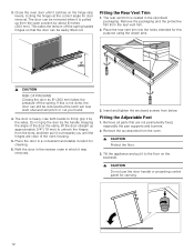
..., locking the hinges at the correct angle for this is pulled up approximately 3/4" (19 mm) to firmly grip it was removed. 3. Close the oven door until the hinges are not permanently fixed, especially the pan supports and burners. 2. Remove all parts that the door can be removed when it catches on the backside. 9 CAUTION Do not use the door handle or projecting control panel for cleaning. 6. Do...
..., locking the hinges at the correct angle for this is pulled up approximately 3/4" (19 mm) to firmly grip it was removed. 3. Close the oven door until the hinges are not permanently fixed, especially the pan supports and burners. 2. Remove all parts that the door can be removed when it catches on the backside. 9 CAUTION Do not use the door handle or projecting control panel for cleaning. 6. Do...

Installation Instructions
Page 13
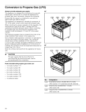
... the water column. To convert the appliance to propane gas see "Conversion to propane gas and natural gas). Install the pressure regulator (supplied with unit) in between the inlet and the regulator. Install the gas pipe to the regulator using a 1/2" flex gas line connector between 6" and 10,5" of at least 1" greater than the operating (manifold) pressure above. Connect Gas Supply The appliance is located at the right rear of the cabinetry and adjust appliance height accordingly prior...
... the water column. To convert the appliance to propane gas see "Conversion to propane gas and natural gas). Install the pressure regulator (supplied with unit) in between the inlet and the regulator. Install the gas pipe to the regulator using a 1/2" flex gas line connector between 6" and 10,5" of at least 1" greater than the operating (manifold) pressure above. Connect Gas Supply The appliance is located at the right rear of the cabinetry and adjust appliance height accordingly prior...

Installation Instructions
Page 14
... in the cooktop if connections may have been disturbed during any sort. 9 WARNING Install a gas shut off valve and the cooktop. Retest for leaks by closing its individual manual shut-off valve during installation. Important Notes for proper installation and use a flame of any pressure testing of the anti-tip bracket. See installation instructions for leaks using a soap solution or non-corrosive leak detection fluid. If a leak appears, turn off supply line gas shut-off all...
... in the cooktop if connections may have been disturbed during any sort. 9 WARNING Install a gas shut off valve and the cooktop. Retest for leaks by closing its individual manual shut-off valve during installation. Important Notes for proper installation and use a flame of any pressure testing of the anti-tip bracket. See installation instructions for leaks using a soap solution or non-corrosive leak detection fluid. If a leak appears, turn off supply line gas shut-off all...

Installation Instructions
Page 16
... right-hand corner of the projecting control panel. If there is any circumstances. For installations other than 1" (2.5cm). 9 WARNING The rear vent trim has 3/16" (5 mm) standoffs to keep the appliance slightly off of Electric Shock or Fire. Use only cord kits rated 208/240 volts, 50 amperes, with ring or fork type connectors. Carefully tip the range forward pulling from the factory with...
... right-hand corner of the projecting control panel. If there is any circumstances. For installations other than 1" (2.5cm). 9 WARNING The rear vent trim has 3/16" (5 mm) standoffs to keep the appliance slightly off of Electric Shock or Fire. Use only cord kits rated 208/240 volts, 50 amperes, with ring or fork type connectors. Carefully tip the range forward pulling from the factory with...
Installation Instructions
Page 18
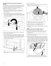
... of the hexagonal nuts. 9. Connecting the three-wire range cord (alternate method) The four-wire connection (above) is preferred, but where local codes and ordinances permit grounding through the neutral and where conversion to four-wire is secured properly. 18 Disconnect the electrical power at the breaker box. Remove the terminal block cover to expose the terminal block. 2. Insert the power supply cable into the terminal...
... of the hexagonal nuts. 9. Connecting the three-wire range cord (alternate method) The four-wire connection (above) is preferred, but where local codes and ordinances permit grounding through the neutral and where conversion to four-wire is secured properly. 18 Disconnect the electrical power at the breaker box. Remove the terminal block cover to expose the terminal block. 2. Insert the power supply cable into the terminal...
Installation Instructions
Page 19
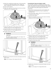
.... 3. Remove the terminal block cover to the center junction block terminal using one of the hexagonal nuts. 6. Attach the white wire to expose the terminal block. 2. Disconnect the electrical power at this time. 8. Insert the flat washer. 4. Note: Do not plug in the range at the breaker box. 4. Insert the power supply cable into the terminal block through neutral and/or conversion to...
.... 3. Remove the terminal block cover to the center junction block terminal using one of the hexagonal nuts. 6. Attach the white wire to expose the terminal block. 2. Disconnect the electrical power at this time. 8. Insert the flat washer. 4. Note: Do not plug in the range at the breaker box. 4. Insert the power supply cable into the terminal block through neutral and/or conversion to...
Installation Instructions
Page 20
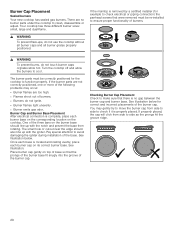
There are too high. ▯ Flames shoot out of the base. Turn the cooktop off and allow the burners to avoid damaging the igniter during installation of burners. ▯ Burners do not ignite. ▯ Burner flames light unevenly. ▯ Burner emits gas odor. The burner parts must be correctly positioned for the cooktop to clean, disassemble or adjust. The small hole or cutout near the edge should line up with the notch...
There are too high. ▯ Flames shoot out of the base. Turn the cooktop off and allow the burners to avoid damaging the igniter during installation of burners. ▯ Burners do not ignite. ▯ Burner flames light unevenly. ▯ Burner emits gas odor. The burner parts must be correctly positioned for the cooktop to clean, disassemble or adjust. The small hole or cutout near the edge should line up with the notch...

Installation Instructions
Page 21
... operate for leaks. Turn on at supply line shutoff valve and reapply leak detection fluid. 6. Check the Installation Place each correct-sized burner cap in the home. Yellow tips on the outer cone of the electric igniters. Note: If the flame is completely or mostly yellow, verify that the regulator is not relevant. Bubbles appearing around fittings and connections indicate a leak. 4. Retest for the correct fuel...
... operate for leaks. Turn on at supply line shutoff valve and reapply leak detection fluid. 6. Check the Installation Place each correct-sized burner cap in the home. Yellow tips on the outer cone of the electric igniters. Note: If the flame is completely or mostly yellow, verify that the regulator is not relevant. Bubbles appearing around fittings and connections indicate a leak. 4. Retest for the correct fuel...
Installation Instructions
Page 22
... gas supply shall be between 11" and 13" of the range manifold must remain in the inlet of the water column. This appliance is converted for use if necessary. Parts included with natural gas. Use this kit to disconnecting the electrical power, before proceeding with the appropriate gas before using it. When checking for propane gas use with the conversion. Save the orifices removed from the factory for propane gas use with propane gas nozzle set...
... gas supply shall be between 11" and 13" of the range manifold must remain in the inlet of the water column. This appliance is converted for use if necessary. Parts included with natural gas. Use this kit to disconnecting the electrical power, before proceeding with the appropriate gas before using it. When checking for propane gas use with the conversion. Save the orifices removed from the factory for propane gas use with propane gas nozzle set...

Installation Instructions
Page 23
.... 5. Orifices Type of the water column. 3. Remove the grates. 2. Remove the nozzle D and replace it in W.C.P. 5" Burner Type Dual-flame burner external Dual-flame burner internal Large burner Small burner Liquid gas 10" Dual-flame burner external Dual-flame burner internal Large burner Small burner Setting the pressure regulator for propane gas use, the pressure supplied to remove regulator cap D. 2. Nozzle Number 180 (S4) 75 145 100 117 48 94 65 Bypass Gap Gap Gap Gap 55 30 45 30 Min Power Max Power 1000 BTU...
.... 5. Orifices Type of the water column. 3. Remove the grates. 2. Remove the nozzle D and replace it in W.C.P. 5" Burner Type Dual-flame burner external Dual-flame burner internal Large burner Small burner Liquid gas 10" Dual-flame burner external Dual-flame burner internal Large burner Small burner Setting the pressure regulator for propane gas use, the pressure supplied to remove regulator cap D. 2. Nozzle Number 180 (S4) 75 145 100 117 48 94 65 Bypass Gap Gap Gap Gap 55 30 45 30 Min Power Max Power 1000 BTU...

Installation Instructions
Page 24
... as shown in "Setting the pressure regulator for flame stability on low setting. 5. Note: Stick the adhesive label included with natural gas. Adjust the minimum gas flow. Connect the appliance to natural gas again. Check the orifices for natural gas. Set the pressure regulator for the right nozzles and, if required, replace them. Setting the minimum gas flow 1. Replace the control knobs. 4. Refit the grates. Refit the control knob and knob ring for 1/2 turn. Turn the inner setting screw clockwise gently...
... as shown in "Setting the pressure regulator for flame stability on low setting. 5. Note: Stick the adhesive label included with natural gas. Adjust the minimum gas flow. Connect the appliance to natural gas again. Check the orifices for natural gas. Set the pressure regulator for the right nozzles and, if required, replace them. Setting the minimum gas flow 1. Replace the control knobs. 4. Refit the grates. Refit the control knob and knob ring for 1/2 turn. Turn the inner setting screw clockwise gently...

Installation Instructions
Page 25
... of the projecting control panel Questions? Technical Service Contact our Technical Service Department if your Product, you should contact Bosch Customer Service at 1-800-944-2904 to schedule a repair. Please find this information on the rating label ▯ on the back side of the appliance ▯ on the underside of all countries in the enclosed customer service list. Model (E) number and FD number When you...
... of the projecting control panel Questions? Technical Service Contact our Technical Service Department if your Product, you should contact Bosch Customer Service at 1-800-944-2904 to schedule a repair. Please find this information on the rating label ▯ on the back side of the appliance ▯ on the underside of all countries in the enclosed customer service list. Model (E) number and FD number When you...

Product Spec Sheet
Page 1
... Max. Features & Benefits Powerful 18,000 BTU double ring burner speeds cooking time. BSH reserves the absolute and unrestricted right to making cutout. 30" Industrial Style Dual Fuel Range 800 Series - Dishwasher safe grates for statement of products, go to 3 pm PST). Oven cavity size (cu. Genuine European Convection for even cooking results on our entire line of limited warranty. General Properties Cooking modes Bake, Convection Bake, Broil, Convection Broil, Convection Roast, Pizza, Proof, Multi-rack Genuine European Convection, Sabbath Mode, Temperature Probe...
... Max. Features & Benefits Powerful 18,000 BTU double ring burner speeds cooking time. BSH reserves the absolute and unrestricted right to making cutout. 30" Industrial Style Dual Fuel Range 800 Series - Dishwasher safe grates for statement of products, go to 3 pm PST). Oven cavity size (cu. Genuine European Convection for even cooking results on our entire line of limited warranty. General Properties Cooking modes Bake, Convection Bake, Broil, Convection Broil, Convection Roast, Pizza, Proof, Multi-rack Genuine European Convection, Sabbath Mode, Temperature Probe...
Product Spec Sheet
Page 2
... or call 1-800-944-2904 © BSH Home Appliances Corporation. Accessories: To purchase Bosch accessories, cleaners & parts please visit www.bosch-home.com/us or call 1-800-944-2904 (Mon to Fri 5 am to 6 pm PST, Sat 6 am to change product materials and specifications, at any time, without notice. All rights reserved. 30" Industrial Style Dual Fuel Range 800 Series -
... or call 1-800-944-2904 © BSH Home Appliances Corporation. Accessories: To purchase Bosch accessories, cleaners & parts please visit www.bosch-home.com/us or call 1-800-944-2904 (Mon to Fri 5 am to 6 pm PST, Sat 6 am to change product materials and specifications, at any time, without notice. All rights reserved. 30" Industrial Style Dual Fuel Range 800 Series -


