Setup Manual
Page 1
..., is not allowed without notice and we will not occur in a particular installation. These limits are trademarks of merchantability or fitness for any party beforehand. Viotech 3200+ Setup Manual FCC Information and Copyright This equipment has been tested and found in this user's manual.
..., is not allowed without notice and we will not occur in a particular installation. These limits are trademarks of merchantability or fitness for any party beforehand. Viotech 3200+ Setup Manual FCC Information and Copyright This equipment has been tested and found in this user's manual.
Setup Manual
Page 2
Table of Contents Chapter 1: Introduction 1 1.1 Before You Start 1 1.2 Package Checklist 1 1.3 Motherboard Features 2 1.4 Rear Panel Connectors 3 1.5 Motherboard Layout 4 Chapter 2: Hardware Installation 5 2.1 Installing Central Processing Unit (CPU 5 2.2 FAN Headers 5 2.3 Installing System Memory 6 2.4 Connectors and Slots 8 Chapter 3: Headers & Jumpers Setup 11 3.1 How to Setup Jumpers 11 3.2 Detail Settings 11 Chapter 4: Useful Help 15 4.1 Driver Installation Note 15 5.2 Extra Information 16 5.3 Troubleshooting 17 Appendix: SPEC In Other ...
Table of Contents Chapter 1: Introduction 1 1.1 Before You Start 1 1.2 Package Checklist 1 1.3 Motherboard Features 2 1.4 Rear Panel Connectors 3 1.5 Motherboard Layout 4 Chapter 2: Hardware Installation 5 2.1 Installing Central Processing Unit (CPU 5 2.2 FAN Headers 5 2.3 Installing System Memory 6 2.4 Connectors and Slots 8 Chapter 3: Headers & Jumpers Setup 11 3.1 How to Setup Jumpers 11 3.2 Detail Settings 11 Chapter 4: Useful Help 15 4.1 Driver Installation Note 15 5.2 Extra Information 16 5.3 Troubleshooting 17 Appendix: SPEC In Other ...
Setup Manual
Page 3
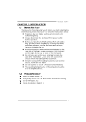
CHAPTER 1: INTRODUCTION Viotech 3200+ 1.1 BEFORE YOU START Thank you take the motherboard out from dangerous area, such as heat source, humid air and water. „ Do not squeeze or ...
CHAPTER 1: INTRODUCTION Viotech 3200+ 1.1 BEFORE YOU START Thank you take the motherboard out from dangerous area, such as heat source, humid air and water. „ Do not squeeze or ...
Setup Manual
Page 4
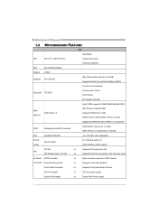
LAN Realtek RTL8103EL 10 / 100 Mb/s auto negotiation Sound Codec VIA VT1708S 5.1 channels audio out High-Definition Audio support PCI slot x1 Supports PCI expansion card Slot PCI Express Gen2 x 16 slot x1 Supports PCI-E x16 expansion card (x8-Lane only) On Board SATA Connector x2 Each connector supports 1 SATA devices Connector Front Panel Connector x1 Supports front panel facilities Front Audio Connector x1 Supports front panel audio function CPU Fan Header x1 CPU Fan power supply System Fan Header x1 System Fan Power supply 2 Motherboard Manual 1.3 ...
LAN Realtek RTL8103EL 10 / 100 Mb/s auto negotiation Sound Codec VIA VT1708S 5.1 channels audio out High-Definition Audio support PCI slot x1 Supports PCI expansion card Slot PCI Express Gen2 x 16 slot x1 Supports PCI-E x16 expansion card (x8-Lane only) On Board SATA Connector x2 Each connector supports 1 SATA devices Connector Front Panel Connector x1 Supports front panel facilities Front Audio Connector x1 Supports front panel audio function CPU Fan Header x1 CPU Fan power supply System Fan Header x1 System Fan Power supply 2 Motherboard Manual 1.3 ...
Setup Manual
Page 5
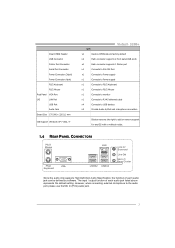
...PS/2 Mouse Real Panel VGA Port I/O LAN Port USB Port Audio Jack Board Size 170 (W) x 220 (L) mm OS Support Windows XP / Vista / 7 Viotech 3200+ SPEC x1 Restore CMOS data to factory default x2 Each connector supports 2 front panel USB ports x1 Each connector supports 1 Printer port x1 Connects to...Mouse x1 Connects to monitor x1 Connects to RJ-45 ethernet cable x4 Connects to USB devices x3 Provide Audio-In/Out and microphone connection Biostar reserves the right to the audio port, please use the Mic In (Pink) audio jack. 3 However, when connecting external microphone to...
...PS/2 Mouse Real Panel VGA Port I/O LAN Port USB Port Audio Jack Board Size 170 (W) x 220 (L) mm OS Support Windows XP / Vista / 7 Viotech 3200+ SPEC x1 Restore CMOS data to factory default x2 Each connector supports 2 front panel USB ports x1 Each connector supports 1 Printer port x1 Connects to...Mouse x1 Connects to monitor x1 Connects to RJ-45 ethernet cable x4 Connects to USB devices x3 Provide Audio-In/Out and microphone connection Biostar reserves the right to the audio port, please use the Mic In (Pink) audio jack. 3 However, when connecting external microphone to...
Setup Manual
Page 6
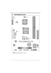
Motherboard Manual 1.5 MOTHERBOARD LAYOUT KBMS1 ATX PW R 2 VGA1 C P U_FA N1 VIA C7-D 1.8G CP U 1 D I MM A 1 D I MM A 2 USB3 J U SB V 2 R J 45U S B1 A U DI O1 LAN VIA VX900 SATA2 F_U S B2 JUSBV1 SATA1 F_USB1 PEX16_1 ATX PW R 1 Codec BAT1 PCI1 Super I/O BIOS J C MOS 1 F_AUDIO1 J_COM1 J_PRINT1 Note: ■ represents the 1st pin. SYS_FAN1 PANEL1 4
Motherboard Manual 1.5 MOTHERBOARD LAYOUT KBMS1 ATX PW R 2 VGA1 C P U_FA N1 VIA C7-D 1.8G CP U 1 D I MM A 1 D I MM A 2 USB3 J U SB V 2 R J 45U S B1 A U DI O1 LAN VIA VX900 SATA2 F_U S B2 JUSBV1 SATA1 F_USB1 PEX16_1 ATX PW R 1 Codec BAT1 PCI1 Super I/O BIOS J C MOS 1 F_AUDIO1 J_COM1 J_PRINT1 Note: ■ represents the 1st pin. SYS_FAN1 PANEL1 4
Setup Manual
Page 7
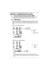
... the red wire is the positive and should be connected to pin#2, and the black wire is Ground and should be different according to pin#1. Viotech 3200+ CHAPTER 2: HARDWARE INSTALLATION 2.1 INSTALLING CENTRAL PROCESSING UNIT (CPU) The motherboard includes an embedded VIA C7-D or Nano processor, and a heatsink has been installed to GND...
... the red wire is the positive and should be connected to pin#2, and the black wire is Ground and should be different according to pin#1. Viotech 3200+ CHAPTER 2: HARDWARE INSTALLATION 2.1 INSTALLING CENTRAL PROCESSING UNIT (CPU) The motherboard includes an embedded VIA C7-D or Nano processor, and a heatsink has been installed to GND...

Setup Manual
Page 8
Align a DIMM on the slot such that the notch on the DIMM matches the break on the Slot. 2. DIM MA 1 DIM MA 2 Motherboard Manual 2.3 INSTALLING SYSTEM MEMORY A. Insert the DIMM vertically and firmly into the slot until the retaining chip snap back in place and the DIMM is properly seated. 6 Unlock a DIMM slot by pressing the retaining clips outward. DDR3 Module 1.
Align a DIMM on the slot such that the notch on the DIMM matches the break on the Slot. 2. DIM MA 1 DIM MA 2 Motherboard Manual 2.3 INSTALLING SYSTEM MEMORY A. Insert the DIMM vertically and firmly into the slot until the retaining chip snap back in place and the DIMM is properly seated. 6 Unlock a DIMM slot by pressing the retaining clips outward. DDR3 Module 1.
Setup Manual
Page 9
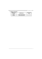
Memory Capacity DIMM Socket Location DIMMA1 DIMMA2 DDR3 Module 512MB/1GB/2GB/4GB 512MB/1GB/2GB/4GB Viotech 3200+ Total Memory Size Max is 8GB. 7 B.
Memory Capacity DIMM Socket Location DIMMA1 DIMMA2 DDR3 Module 512MB/1GB/2GB/4GB 512MB/1GB/2GB/4GB Viotech 3200+ Total Memory Size Max is 8GB. 7 B.

Setup Manual
Page 10
Motherboard Manual 2.4 CONNECTORS AND SLOTS SATA1/SATA2: Serial ATA Connectors The motherboard has a PCI to CPU power circuit. Please make sure this connector has been plugged in perfectly. 32 4 1 Pin Assignment 1 +12V 2 +12V 3 Ground 4 Ground 8 SATA2 SATA1 Pin Assignment 1 Ground 2 TX+ 3 TX- 7 4 Ground 4 5 RX- 6 RX+ 1 7 Ground ATXPWR2: ATX Power Source Connector This connector provides +12V to SATA Controller with 2 channels SATA interface, it satisfies the SATA 2.0 spec and with transfer rate of 3Gb/s.
Motherboard Manual 2.4 CONNECTORS AND SLOTS SATA1/SATA2: Serial ATA Connectors The motherboard has a PCI to CPU power circuit. Please make sure this connector has been plugged in perfectly. 32 4 1 Pin Assignment 1 +12V 2 +12V 3 Ground 4 Ground 8 SATA2 SATA1 Pin Assignment 1 Ground 2 TX+ 3 TX- 7 4 Ground 4 5 RX- 6 RX+ 1 7 Ground ATXPWR2: ATX Power Source Connector This connector provides +12V to SATA Controller with 2 channels SATA interface, it satisfies the SATA 2.0 spec and with transfer rate of 3Gb/s.
Setup Manual
Page 11
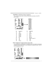
PCI1 9 Viotech 3200+ ATXPWR1: ATX Power Source Connector This connector allows user to connect 24-pin power connector on the ATX power supply. 12 24 1 13 Pin Assignment ...
PCI1 9 Viotech 3200+ ATXPWR1: ATX Power Source Connector This connector allows user to connect 24-pin power connector on the ATX power supply. 12 24 1 13 Pin Assignment ...
Setup Manual
Page 12
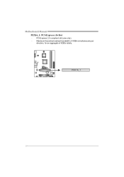
Maximum theoretical realized bandwidth of 4GB/s simultaneously per direction, for an aggregate of 8GB/s totally. Motherboard Manual PEX16_1: PCI-Express x16 Slot - PEX16_1 10 PCI-Express 2.0 compliant (x8-Lane only). -
Maximum theoretical realized bandwidth of 4GB/s simultaneously per direction, for an aggregate of 8GB/s totally. Motherboard Manual PEX16_1: PCI-Express x16 Slot - PEX16_1 10 PCI-Express 2.0 compliant (x8-Lane only). -
Setup Manual
Page 13
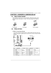
... 15 16 Assignment N/A N/A N/A Power LED (+) Power LED (+) Power LED (-) Power button Ground Function N/A N/A Power LED Power-on , Reset, HDD LED, Power LED, and speaker connections. Viotech 3200+ CHAPTER 3: HEADERS & JUMPERS SETUP 3.1 HOW TO SETUP JUMPERS The illustration shows how to connect the PC case's front panel switch functions. It allows user to...
... 15 16 Assignment N/A N/A N/A Power LED (+) Power LED (+) Power LED (-) Power button Ground Function N/A N/A Power LED Power-on , Reset, HDD LED, Power LED, and speaker connections. Viotech 3200+ CHAPTER 3: HEADERS & JUMPERS SETUP 3.1 HOW TO SETUP JUMPERS The illustration shows how to connect the PC case's front panel switch functions. It allows user to...
Setup Manual
Page 14
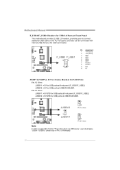
JUSBV2: +5V for USB ports at front panel (F_USB1/F_USB2). Pin 2-3 Close: JUSBV1: +5V STB for USB ports at USB3/RJ45USB1. JUSBV2: +5V STB for USB ports at front panel (F_USB1/F_USB2). F_USB2 F_USB1 10 9 2 1 Pin Assignment 1 +5V (fused) 2 +5V (fused) 3 USB4 USB5 USB+ 6 USB+ 7 Ground 8 Ground 9 Key 10 NC JUSBV1/JUSBV2: Power Source Headers for USB Ports Pin 1-2 Close: JUSBV1: +5V for USB ports at USB3/RJ45USB1. Motherboard Manual F_USB1/F_USB2: Headers for USB 2.0 Ports at Front Panel This motherboard provides 2 USB 2.0 headers, providing user to support this function "...
JUSBV2: +5V for USB ports at front panel (F_USB1/F_USB2). Pin 2-3 Close: JUSBV1: +5V STB for USB ports at USB3/RJ45USB1. JUSBV2: +5V STB for USB ports at front panel (F_USB1/F_USB2). F_USB2 F_USB1 10 9 2 1 Pin Assignment 1 +5V (fused) 2 +5V (fused) 3 USB4 USB5 USB+ 6 USB+ 7 Ground 8 Ground 9 Key 10 NC JUSBV1/JUSBV2: Power Source Headers for USB Ports Pin 1-2 Close: JUSBV1: +5V for USB ports at USB3/RJ45USB1. Motherboard Manual F_USB1/F_USB2: Headers for USB 2.0 Ports at Front Panel This motherboard provides 2 USB 2.0 headers, providing user to support this function "...
Setup Manual
Page 15
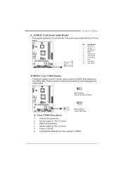
Viotech 3200+ F_AUDIO1: Front Panel Audio Header This header allows user to connect the front audio output cable with the PC front panel. 2 10 Pin Assignment 1 Mic ...
Viotech 3200+ F_AUDIO1: Front Panel Audio Header This header allows user to connect the front audio output cable with the PC front panel. 2 10 Pin Assignment 1 Mic ...
Setup Manual
Page 16
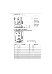
Assignment Carrier detect Received data Transmitted data Data terminal ready Signal ground Data set ready Request to send Clear to connector printer on the PC. Pin 1 2 3 4 5 6 7 2 10 8 9 10 1 9 J_PRINT1: Printer Port Connector This header allows you to send Ring indicator NC Pin Assignment 1 -Strobe 2 -ALF 3 Data 0 4 -Error 5 Data 1 6 -Init 7 Data 2 8 -Scltin 9 Data 3 10 Ground 11 Data 4 12 Ground 13 Data 5 2 26 1 25 Pin Assignment 14 Ground 15 Data 6 16 Ground 17 Data 7 18 Ground 19 -ACK 20 Ground 21 Busy 22 Ground 23 PE ...
Assignment Carrier detect Received data Transmitted data Data terminal ready Signal ground Data set ready Request to send Clear to connector printer on the PC. Pin 1 2 3 4 5 6 7 2 10 8 9 10 1 9 J_PRINT1: Printer Port Connector This header allows you to send Ring indicator NC Pin Assignment 1 -Strobe 2 -ALF 3 Data 0 4 -Error 5 Data 1 6 -Init 7 Data 2 8 -Scltin 9 Data 3 10 Ground 11 Data 4 12 Ground 13 Data 5 2 26 1 25 Pin Assignment 14 Ground 15 Data 6 16 Ground 17 Data 7 18 Ground 19 -ACK 20 Ground 21 Busy 22 Ground 23 PE ...
Setup Manual
Page 17
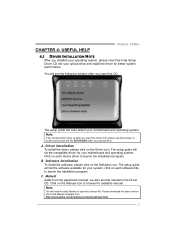
... will list the compatible driver for available manual. Note: You will need Acrobat Reader to browse for your motherboard and operating system. CHAPTER 4: USEFUL HELP Viotech 3200+ 4.1 DRIVER INSTALLATION NOTE After you insert the CD The setup guide will auto detect your motherboard and operating system. A. Note: If this window didn't show...
... will list the compatible driver for available manual. Note: You will need Acrobat Reader to browse for your motherboard and operating system. CHAPTER 4: USEFUL HELP Viotech 3200+ 4.1 DRIVER INSTALLATION NOTE After you insert the CD The setup guide will auto detect your motherboard and operating system. A. Note: If this window didn't show...
Setup Manual
Page 18
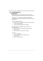
After confirmed, please follow steps below to avoid a damage of the CPU, and the system may not power on the system again. 16 Wait for minutes, that means the CPU protection function has been activated. Power on again. Motherboard Manual 5.2 EXTRA INFORMATION CPU Overheated If the system shutdown automatically after power on system for seconds. 3. CPU fan speed is placed evenly with the CPU speed. Plug in the power cord and boot up the system. The CPU cooler surface is fulfilling with the CPU surface. 2. Remove the power cord from power supply for seconds. 3. In this ...
After confirmed, please follow steps below to avoid a damage of the CPU, and the system may not power on the system again. 16 Wait for minutes, that means the CPU protection function has been activated. Power on again. Motherboard Manual 5.2 EXTRA INFORMATION CPU Overheated If the system shutdown automatically after power on system for seconds. 3. CPU fan speed is placed evenly with the CPU speed. Plug in the power cord and boot up the system. The CPU cooler surface is fulfilling with the CPU surface. 2. Remove the power cord from power supply for seconds. 3. In this ...
Setup Manual
Page 19
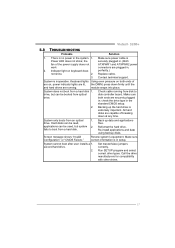
... system. 1. Back up the hard drive is extremely important. System cannot boot after user installs a 1. Call the drive manufacturers for compatibility with other drives. 17 Viotech 3200+ 5.3 TROUBLESHOOTING Probable Solution 1. Replace cable. 3. System is in ; drive. Screen message shows "Invalid Configuration" or "CMOS Failure." Review system's equipment. Set master/slave jumpers correctly...
... system. 1. Back up the hard drive is extremely important. System cannot boot after user installs a 1. Call the drive manufacturers for compatibility with other drives. 17 Viotech 3200+ 5.3 TROUBLESHOOTING Probable Solution 1. Replace cable. 3. System is in ; drive. Screen message shows "Invalid Configuration" or "CMOS Failure." Review system's equipment. Set master/slave jumpers correctly...