Bios Setup
Page 2
... this motherboard. T he rest of this manual will to CMOS RAM. Plug and Pla y Support T his AMI BIOS supports Version 1.1&1.2 of the Advanced Power Management (APM) speci fication. APM Support T his AMI BIOS supports the Plug and Play Version 1.0A specification. Sleep and Suspend power man agement modes are supported. TPower N750 BIOS...
... this motherboard. T he rest of this manual will to CMOS RAM. Plug and Pla y Support T his AMI BIOS supports Version 1.1&1.2 of the Advanced Power Management (APM) speci fication. APM Support T his AMI BIOS supports the Plug and Play Version 1.0A specification. Sleep and Suspend power man agement modes are supported. TPower N750 BIOS...
Bios Setup
Page 3
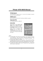
...BIOS settings apply for that may be chang ed without notice. Supported CP Us T his AMI BIOS also supports Version 2.3 of the motherboard. Using Setup When starting up the computer, press during the Power-On Self-Test (POST) to ensure system's compatibility and stability. General...providing a brief description of this manual. DRAM S upport DDR2 SDRAM (Double Data Rate II Synchronous DRAM) is being continuously updated. TPower N750 BIOS Manual PCI Bus Support T his AMI BIOS supports the AMD CPU. Navigation Keys for most conditions to ensure optimum performan ce of...
...BIOS settings apply for that may be chang ed without notice. Supported CP Us T his AMI BIOS also supports Version 2.3 of the motherboard. Using Setup When starting up the computer, press during the Power-On Self-Test (POST) to ensure system's compatibility and stability. General...providing a brief description of this manual. DRAM S upport DDR2 SDRAM (Double Data Rate II Synchronous DRAM) is being continuously updated. TPower N750 BIOS Manual PCI Bus Support T his AMI BIOS supports the AMD CPU. Navigation Keys for most conditions to ensure optimum performan ce of...

Bios Setup
Page 15
... the USB resume from S3/S4 function. Windows Server 2003) must support headless operation. A headless server is a server-speci fic feature. TPower N750 BIOS Manual ACPI APIC support T his item allows you control the wake on LAN (WOL) function. Options: Disabled (Default) / Enabled...table. Options: Enabled (Default) / Disabled AMI OEMB table Set this value to allow the ACPIBIOS to add a pointer to enable or disable the motherboard's APIC (Advan ced Programmable Interrupt Controller). Options: Disabled (Default) / Enabled Resume By RTC Alarm When " Enabled", you can choose which the ...
... the USB resume from S3/S4 function. Windows Server 2003) must support headless operation. A headless server is a server-speci fic feature. TPower N750 BIOS Manual ACPI APIC support T his item allows you control the wake on LAN (WOL) function. Options: Disabled (Default) / Enabled...table. Options: Enabled (Default) / Disabled AMI OEMB table Set this value to allow the ACPIBIOS to add a pointer to enable or disable the motherboard's APIC (Advan ced Programmable Interrupt Controller). Options: Disabled (Default) / Enabled Resume By RTC Alarm When " Enabled", you can choose which the ...

Setup Manual
Page 2
Table of Contents Chapter 1: Introduction 1 1.1 Before You Start 1 1.2 Package Checklist 1 1.3 Motherboard Features 2 1.4 Rear Panel Connectors 3 1.5 Motherboard Layout 4 Chapter 2: Hardware Installation 5 2.1 Installing Central Processing Unit (CPU 5 2.2 FAN Headers 7 2.3 Installing System Memory 8 2.4 Connectors and Slots 10 Chapter 3: Headers & Jumpers Setup 13 3.1 How to ...
Table of Contents Chapter 1: Introduction 1 1.1 Before You Start 1 1.2 Package Checklist 1 1.3 Motherboard Features 2 1.4 Rear Panel Connectors 3 1.5 Motherboard Layout 4 Chapter 2: Hardware Installation 5 2.1 Installing Central Processing Unit (CPU 5 2.2 FAN Headers 7 2.3 Installing System Memory 8 2.4 Connectors and Slots 10 Chapter 3: Headers & Jumpers Setup 13 3.1 How to ...

Setup Manual
Page 3
...cause short circuits which may differ by touching any unfastened small parts inside the case after installation. Before you start installing the motherboard, please make sure you follow the instructions below: „ Prepare a dry and stable working environment with sufficient lighting. ...optional) DVI to remove the static charge. „ Avoid touching the components on motherboard or the rear side of the board unless necessary. CHAPTER 1: INTRODUCTION TPower N750 1.1 BEFORE YOU START Thank you take the motherboard out from dangerous area, such as heat source, humid air and water. 1.2...
...cause short circuits which may differ by touching any unfastened small parts inside the case after installation. Before you start installing the motherboard, please make sure you follow the instructions below: „ Prepare a dry and stable working environment with sufficient lighting. ...optional) DVI to remove the static charge. „ Avoid touching the components on motherboard or the rear side of the board unless necessary. CHAPTER 1: INTRODUCTION TPower N750 1.1 BEFORE YOU START Thank you take the motherboard out from dangerous area, such as heat source, humid air and water. 1.2...
Setup Manual
Page 4
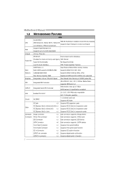
... Ultra DMA 33 / 66 / 100 / 133 Bus Master Mode supports PIO Mode 0~4 SATA II Integrated Serial ATA Controller Data transfer rates up to 3 Gb/s. Motherboard Manual 1.3 MOTHERBOARD FEATURES SPEC Socket AM2+ AMD 64 Architecture enables 32 and 64 bit computing CPU AMD Athlon 64 / Athlon 64 FX / Athlon 64 Supports Hyper Transport...
... Ultra DMA 33 / 66 / 100 / 133 Bus Master Mode supports PIO Mode 0~4 SATA II Integrated Serial ATA Controller Data transfer rates up to 3 Gb/s. Motherboard Manual 1.3 MOTHERBOARD FEATURES SPEC Socket AM2+ AMD 64 Architecture enables 32 and 64 bit computing CPU AMD Athlon 64 / Athlon 64 FX / Athlon 64 Supports Hyper Transport...

Setup Manual
Page 6
Motherboard Manual 1.5 MOTHERBOARD LAYOUT DVI JKBMS1 JATXPWR2 JNFAN1 DIMMB2 DIMMA2 DIMMB1 DIMMA1 JUSB2 JUSB1 Socket AM2+ JUS BLAN1 JCFAN1 IDE1 BIOS JAUDIO2 LAN PCIEX12V_CON1 PEX16-1 JPSLI1 JPSLI3 JPSLI5 ...
Motherboard Manual 1.5 MOTHERBOARD LAYOUT DVI JKBMS1 JATXPWR2 JNFAN1 DIMMB2 DIMMA2 DIMMB1 DIMMA1 JUSB2 JUSB1 Socket AM2+ JUS BLAN1 JCFAN1 IDE1 BIOS JAUDIO2 LAN PCIEX12V_CON1 PEX16-1 JPSLI1 JPSLI3 JPSLI5 ...

Setup Manual
Page 8
... the installation. Connect the CPU FAN power cable to the latest version while using new AM2+ CPUs. Note: Please update the BIOS to the JCFAN1. Motherboard Manual Step 4: Hold the CPU down firmly, and then close the lever toward direct B to complete the installation.
... the installation. Connect the CPU FAN power cable to the latest version while using new AM2+ CPUs. Note: Please update the BIOS to the JCFAN1. Motherboard Manual Step 4: Hold the CPU down firmly, and then close the lever toward direct B to complete the installation.

Setup Manual
Page 10
Unlock a DIMM slot by pressing the retaining clips outward. Insert the DIMM vertically and firmly into the slot until the retaining chip snap back in place and the DIMM is properly seated. 8 Memory Modules DIMMB2 DIMMA2 DIMMB1 DIMMA1 1. Align a DIMM on the slot such that the notch on the DIMM matches the break on the Slot. 2. Motherboard Manual 2.3 INSTALLING SYSTEM MEMORY A.
Unlock a DIMM slot by pressing the retaining clips outward. Insert the DIMM vertically and firmly into the slot until the retaining chip snap back in place and the DIMM is properly seated. 8 Memory Modules DIMMB2 DIMMA2 DIMMB1 DIMMA1 1. Align a DIMM on the slot such that the notch on the DIMM matches the break on the Slot. 2. Motherboard Manual 2.3 INSTALLING SYSTEM MEMORY A.

Setup Manual
Page 11
... memory module of the motherboard, the memory module must be the same (x8 or x16) 9 B. Memory Capacity DIMM Socket Location DIMMA1 DIMMB1 DIMMA2 DIMMB2 DDR2 Module 256MB/512MB/1GB/2GB/4GB 256MB/512MB/1GB/2GB/4GB 256MB/512MB/1GB/2GB/4GB 256MB/512MB/1GB/2GB/4GB TPower N750 Total Memory Size Max is...
... memory module of the motherboard, the memory module must be the same (x8 or x16) 9 B. Memory Capacity DIMM Socket Location DIMMA1 DIMMB1 DIMMA2 DIMMB2 DDR2 Module 256MB/512MB/1GB/2GB/4GB 256MB/512MB/1GB/2GB/4GB 256MB/512MB/1GB/2GB/4GB 256MB/512MB/1GB/2GB/4GB TPower N750 Total Memory Size Max is...

Setup Manual
Page 12
Motherboard Manual 2.4 CONNECTORS AND SLOTS FDD1: Floppy Disk Connector The motherboard provides a standard floppy disk connector that provides PIO Mode 0~4, Bus Master, and Ultra DMA 33/66/100/133 functionality. The IDE connector can connect a master and a slave drive, so you can connect up to two hard disk drives. 40 39 21 10 This connector supports the provided floppy drive ribbon cables. 2 34 1 33 IDE1: Hard Disk Connector The motherboard has a 32-bit Enhanced IDE Controller that supports 360K, 720K, 1.2M, 1.44M and 2.88M floppy disk types.
Motherboard Manual 2.4 CONNECTORS AND SLOTS FDD1: Floppy Disk Connector The motherboard provides a standard floppy disk connector that provides PIO Mode 0~4, Bus Master, and Ultra DMA 33/66/100/133 functionality. The IDE connector can connect a master and a slave drive, so you can connect up to two hard disk drives. 40 39 21 10 This connector supports the provided floppy drive ribbon cables. 2 34 1 33 IDE1: Hard Disk Connector The motherboard has a 32-bit Enhanced IDE Controller that supports 360K, 720K, 1.2M, 1.44M and 2.88M floppy disk types.

Setup Manual
Page 13
... transfer bandwidth up to x16 speed, then PEX16-2 would not be functional. PCI-Express Gen2 supports a raw bit-rate of this motherboard supports dual PCI-Express graphics cards using NVIDIA's SLI technology with multiple displays. PCI-Express 2.0 compliant. - When using SLI, this..., please refer to the instructions of 16GB/s(8GB/s SLI) totally. - This slot is master and runs with multiple displays. PCI-Express 2.0 compliant. - TPower N750 PEX16-1: PCI-Express Gen2 x16(x16/SLI x8 Speed) Slot - If PEX16-1 is reserved for graphics or video cards. PEX16-1 PEX1_1 PEX16-2 11 To ...
... transfer bandwidth up to x16 speed, then PEX16-2 would not be functional. PCI-Express Gen2 supports a raw bit-rate of this motherboard supports dual PCI-Express graphics cards using NVIDIA's SLI technology with multiple displays. PCI-Express 2.0 compliant. - When using SLI, this..., please refer to the instructions of 16GB/s(8GB/s SLI) totally. - This slot is master and runs with multiple displays. PCI-Express 2.0 compliant. - TPower N750 PEX16-1: PCI-Express Gen2 x16(x16/SLI x8 Speed) Slot - If PEX16-1 is reserved for graphics or video cards. PEX16-1 PEX1_1 PEX16-2 11 To ...

Setup Manual
Page 14
PCI stands for Peripheral Component Interconnect, and it is designated as 32 bits. PCI1 PCI2 PCI3 12 This PCI slot is a bus standard for expansion cards. Motherboard Manual PCI1~PCI3: Peripheral Component Interconnect Slots This motherboard is equipped with 3 standard PCI slots.
PCI stands for Peripheral Component Interconnect, and it is designated as 32 bits. PCI1 PCI2 PCI3 12 This PCI slot is a bus standard for expansion cards. Motherboard Manual PCI1~PCI3: Peripheral Component Interconnect Slots This motherboard is equipped with 3 standard PCI slots.

Setup Manual
Page 16
... will provide +12V to connect 24-pin power connector on the system, please make sure that both JATXPWR1 and JATXPWR2 connectors have been plugged-in. Motherboard Manual JATXPWR1: ATX Power Source Connector This connector allows user to CPU power circuit. 8 4 Pin Assignment 1 +12V 2 +12V 5 1 3 +12V 4 +12V 5 Ground 6 Ground 7 Ground 8 Ground Note...
... will provide +12V to connect 24-pin power connector on the system, please make sure that both JATXPWR1 and JATXPWR2 connectors have been plugged-in. Motherboard Manual JATXPWR1: ATX Power Source Connector This connector allows user to CPU power circuit. 8 4 Pin Assignment 1 +12V 2 +12V 5 1 3 +12V 4 +12V 5 Ground 6 Ground 7 Ground 8 Ground Note...

Setup Manual
Page 18
... jumper to "Pin 2-3 close ". 5. Set the jumper to "Pin 1-2 close ". 3. Reset your desired password or clear the CMOS data. 16 Wait for five seconds. 4. Motherboard Manual JCDIN1: CD-ROM Audio-in Connector This connector allows user to connect the audio source from the variaty devices, like CD-ROM, DVD-ROM... Power on pin2-3, it allows user to restore the BIOS safe setting and the CMOS data, please carefully follow the procedures to avoid damaging the motherboard. 3 1 Pin 1-2 Close: Normal Operation (default). 3 1 3 1 Pin 2-3 Close: Clear CMOS data. ※ Clear CMOS Procedures: 1.
... jumper to "Pin 2-3 close ". 5. Set the jumper to "Pin 1-2 close ". 3. Reset your desired password or clear the CMOS data. 16 Wait for five seconds. 4. Motherboard Manual JCDIN1: CD-ROM Audio-in Connector This connector allows user to connect the audio source from the variaty devices, like CD-ROM, DVD-ROM... Power on pin2-3, it allows user to restore the BIOS safe setting and the CMOS data, please carefully follow the procedures to avoid damaging the motherboard. 3 1 Pin 1-2 Close: Normal Operation (default). 3 1 3 1 Pin 2-3 Close: Clear CMOS data. ※ Clear CMOS Procedures: 1.

Setup Manual
Page 19
TPower N750 2 1 25 Pin Assignment Pin Assignment 1 -Strobe 2 -ALF 14 Ground 15 Data 6 3 Data 0 4 -Error 16 Ground 17 Data 7 5 Data 1 6 -Init 7 Data 2 18 Ground 19 -ACK 20 ... 3 21 Busy 22 Ground 10 Ground 11 Data 4 12 Ground 23 PE 24 Ground 25 SCLT 13 Data 5 26 Key JCOM1: Serial port Connector The motherboard has a Serial Port Connector for connecting RS-232 Port. 2 10 1 9 Pin Assignment 1 Carrier detect 2 Received data 3 Transmitted data 4 Data terminal ready 5 Signal ground 6 Data set...
TPower N750 2 1 25 Pin Assignment Pin Assignment 1 -Strobe 2 -ALF 14 Ground 15 Data 6 3 Data 0 4 -Error 16 Ground 17 Data 7 5 Data 1 6 -Init 7 Data 2 18 Ground 19 -ACK 20 ... 3 21 Busy 22 Ground 10 Ground 11 Data 4 12 Ground 23 PE 24 Ground 25 SCLT 13 Data 5 26 Key JCOM1: Serial port Connector The motherboard has a Serial Port Connector for connecting RS-232 Port. 2 10 1 9 Pin Assignment 1 Carrier detect 2 Received data 3 Transmitted data 4 Data terminal ready 5 Signal ground 6 Data set...

Setup Manual
Page 20
...item, and lighted LED means that system item is in normal status. On-Board LED Indicators There are 6 LED indicators on the motherboard to the chipset's specification, SATA5 and SATA6 do not support SATA mode, only support AHCI+RAID mode. LED_D6 LED_D5 LED_D1 LED_D2 ... SATA6 Pin Assignment 1 Ground 2 TX+ 3 TX- 7 4 Ground 5 RX- 4 6 RX+ 7 Ground 1 Note: Due to show system status. Motherboard Manual SATA1~SATA6: Serial ATA Connectors The motherboard has a PCI to SATA Controller with 6 channels SATA interface, it satisfies the SATA 2.0 spec and with transfer rate of 3.0Gb/s.
...item, and lighted LED means that system item is in normal status. On-Board LED Indicators There are 6 LED indicators on the motherboard to the chipset's specification, SATA5 and SATA6 do not support SATA mode, only support AHCI+RAID mode. LED_D6 LED_D5 LED_D1 LED_D2 ... SATA6 Pin Assignment 1 Ground 2 TX+ 3 TX- 7 4 Ground 5 RX- 4 6 RX+ 7 Ground 1 Note: Due to show system status. Motherboard Manual SATA1~SATA6: Serial ATA Connectors The motherboard has a PCI to SATA Controller with 6 channels SATA interface, it satisfies the SATA 2.0 spec and with transfer rate of 3.0Gb/s.

Setup Manual
Page 22
...-2. and PEX16-1 and PEX16-2 will not be set to use the SLI function, these jumpers determines the operation mode of these jumpers should be functional. Motherboard Manual PCIEX12V_CON1: Auxiliary Power for Graphics This connector is an auxiliary power connection for the graphics card provides better graphics performance. JPSLI1 JPSLI3 JPSLI5 JPSLI7...
...-2. and PEX16-1 and PEX16-2 will not be set to use the SLI function, these jumpers determines the operation mode of these jumpers should be functional. Motherboard Manual PCIEX12V_CON1: Auxiliary Power for Graphics This connector is an auxiliary power connection for the graphics card provides better graphics performance. JPSLI1 JPSLI3 JPSLI5 JPSLI7...

Setup Manual
Page 24
... on two graphic cards Step 7: To securely fix the connector between the two graphics cards. Step 7-2: Align and insert the retention bracket into slots completely. Motherboard Manual PEX16-1 PEX16-2 Notice: Make sure both the graphics cards are seated into the slot and then fix it with a screw. Front view Side view...
... on two graphic cards Step 7: To securely fix the connector between the two graphics cards. Step 7-2: Align and insert the retention bracket into slots completely. Motherboard Manual PEX16-1 PEX16-2 Notice: Make sure both the graphics cards are seated into the slot and then fix it with a screw. Front view Side view...

Setup Manual
Page 26
... reads and writes across multiple drives in parallel. No capacity loss penalty for parity. Drawbacks: Does not deliver any drive in RAID 0 and RAID 1. Motherboard Manual CHAPTER 5: NVIDIA RAID FUNCTIONS 5.1 OPERATION SYSTEM Supports Windows XP and Windows VISTA. 5.2 RAID ARRAYS NVRAID supports the following types of RAID arrays: RAID 0: RAID...
... reads and writes across multiple drives in parallel. No capacity loss penalty for parity. Drawbacks: Does not deliver any drive in RAID 0 and RAID 1. Motherboard Manual CHAPTER 5: NVIDIA RAID FUNCTIONS 5.1 OPERATION SYSTEM Supports Windows XP and Windows VISTA. 5.2 RAID ARRAYS NVRAID supports the following types of RAID arrays: RAID 0: RAID...

