

MOTHER BOARD MANUAL
Page 2
... 3 1.1 Before You Start 3 1.2 Package Checklist 3 1.3 Motherboard Features 4 1.4 Rear Panel Connectors 6 1.5 Motherboard Layout 7 Chapter 2: Hardware Installation 8 2.1 Installing Central Processing Unit (CPU 8 2.2 FAN Headers 10 2.3 Installing System Memory 11 2.4 Connectors and Slots 13 Chapter 3: Headers & Jumpers Setup 15 3.1 How to Setup Jumpers 15 3.2 Detail Settings 15 Chapter 4: RAID Functions 23 4.1 Operation System 23...
... 3 1.1 Before You Start 3 1.2 Package Checklist 3 1.3 Motherboard Features 4 1.4 Rear Panel Connectors 6 1.5 Motherboard Layout 7 Chapter 2: Hardware Installation 8 2.1 Installing Central Processing Unit (CPU 8 2.2 FAN Headers 10 2.3 Installing System Memory 11 2.4 Connectors and Slots 13 Chapter 3: Headers & Jumpers Setup 15 3.1 How to Setup Jumpers 15 3.2 Detail Settings 15 Chapter 4: RAID Functions 23 4.1 Operation System 23...

MOTHER BOARD MANUAL
Page 4
... Integrated Serial ATA Controller Integrated Serial ATA Controller SATA II Data transfer rates up to 3 Gb/s. Motherboard Manual 1.3 MOTHERBOARD FEATURES TF7150U-M7 TF7100P-M7 LGA 775 LGA 775 Intel Core2Duo / Core2Quad / Celeron 4xx / Intel Core2Duo / Core2Quad / Celeron 4xx / Pentium D / ... Enhanced Intel SpeedStep® / Intel / Enhanced Intel SpeedStep® / Intel Architecture-64 / Extended Memory 64 Architecture-64 / Extended Memory 64 Technology / Virtualization Technology Technology / Virtualization Technology FSB Support 1333 MHz Support 1333 MHz Chipset GeForce ...
... Integrated Serial ATA Controller Integrated Serial ATA Controller SATA II Data transfer rates up to 3 Gb/s. Motherboard Manual 1.3 MOTHERBOARD FEATURES TF7150U-M7 TF7100P-M7 LGA 775 LGA 775 Intel Core2Duo / Core2Quad / Celeron 4xx / Intel Core2Duo / Core2Quad / Celeron 4xx / Pentium D / ... Enhanced Intel SpeedStep® / Intel / Enhanced Intel SpeedStep® / Intel Architecture-64 / Extended Memory 64 Architecture-64 / Extended Memory 64 Technology / Virtualization Technology Technology / Virtualization Technology FSB Support 1333 MHz Support 1333 MHz Chipset GeForce ...

MOTHER BOARD MANUAL
Page 11
Unlock a DIMM slot by pressing the retaining clips outward. 2.3 INSTALLING SYSTEM MEMORY A. Align a DIMM on the slot such that the notch on the DIMM matches the break on the Slot. 11 Memory Modules TF7150U-M7/TF7100P-M7 DIMMA1 DIMMA2 1.
Unlock a DIMM slot by pressing the retaining clips outward. 2.3 INSTALLING SYSTEM MEMORY A. Align a DIMM on the slot such that the notch on the DIMM matches the break on the Slot. 11 Memory Modules TF7150U-M7/TF7100P-M7 DIMMA1 DIMMA2 1.

MOTHER BOARD MANUAL
Page 12
Insert the DIMM vertically and firmly into the slot until the retaining chip snap back in place and the DIMM is 4GB. 12 Motherboard Manual 2. B. Memory Capacity DIMM Socket Location DIMMA1 DIMMA2 DDR2 Module 512MB/1024MB/2048MB 512MB/1024MB/2048MB Total Memory Size Max is properly seated.
Insert the DIMM vertically and firmly into the slot until the retaining chip snap back in place and the DIMM is 4GB. 12 Motherboard Manual 2. B. Memory Capacity DIMM Socket Location DIMMA1 DIMMA2 DDR2 Module 512MB/1024MB/2048MB 512MB/1024MB/2048MB Total Memory Size Max is properly seated.

MOTHER BOARD MANUAL
Page 21
On-Board LED Indicators There are 2 on -board Power Switch button. Memory Error VGA Error Normal 21 Please refer to show system status. LED_D1 LED_D2 LED_D1 and LED_D2: These 2 LED indicate system power on the motherboard to the table below for different messages: LED_D2 OFF OFF ON ON LED_D1 OFF ON OFF ON Message Abnormal: CPU / Chipset error. On-Board Buttons There are 2 LED indicators on diagnostics. TF7150U-M7/TF7100P-M7 RSTSW1 PWRSW1 PWRSW1: This is an on-board Reset button. RSTSW1: This is an on -board buttons.
On-Board LED Indicators There are 2 on -board Power Switch button. Memory Error VGA Error Normal 21 Please refer to show system status. LED_D1 LED_D2 LED_D1 and LED_D2: These 2 LED indicate system power on the motherboard to the table below for different messages: LED_D2 OFF OFF ON ON LED_D1 OFF ON OFF ON Message Abnormal: CPU / Chipset error. On-Board Buttons There are 2 LED indicators on diagnostics. TF7150U-M7/TF7100P-M7 RSTSW1 PWRSW1 PWRSW1: This is an on-board Reset button. RSTSW1: This is an on -board buttons.
MOTHER BOARD MANUAL
Page 27
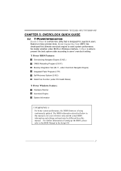
TF7150U-M7/TF7100P-M7 CHAPTER 5: OVERCLOCK QUICK GUIDE 5.1 T-POWER INTRODUCTION Biostar T-Power is a whole new utility that is for overclock users. For further information of setting up the BIOS, ...for your reference only and the actual BIOS information and settings on many precise tests, Biostar Engineering Team (BET) has developed this manual. WARNING !! T-Power BIOS Features: Overclocking Navigator Engine (O.N.E.) CMOS Reloading Program (C.R.P.) Memory Integration Test (M.I.T., under Overclock Navigator Engine) Integrated Flash Program (I.F.P.) Self Recovery System (S.R.S)...
TF7150U-M7/TF7100P-M7 CHAPTER 5: OVERCLOCK QUICK GUIDE 5.1 T-POWER INTRODUCTION Biostar T-Power is a whole new utility that is for overclock users. For further information of setting up the BIOS, ...for your reference only and the actual BIOS information and settings on many precise tests, Biostar Engineering Team (BET) has developed this manual. WARNING !! T-Power BIOS Features: Overclocking Navigator Engine (O.N.E.) CMOS Reloading Program (C.R.P.) Memory Integration Test (M.I.T., under Overclock Navigator Engine) Integrated Flash Program (I.F.P.) Self Recovery System (S.R.S)...

MOTHER BOARD MANUAL
Page 29
TF7150U-M7/TF7100P-M7 FSB-Me mory Clock Mode This item allows you to choose the memory ratio. FSB-Me mory Ratio This item allows you to increase the system performance, named A.O.S. NB Voltage: This function will increase memory stability when overclocking. Based on many tests and experiments,...(A.O.S.) For beginners in a single step. 29 FSB (QDR), MHz This item allows you to set the memory frequency. However, the CPU temperature will increase memory stability when overclocking. CPU Voltage This function will increase CPU stability when overclocking. MEM (DDR), MHz This item...
TF7150U-M7/TF7100P-M7 FSB-Me mory Clock Mode This item allows you to choose the memory ratio. FSB-Me mory Ratio This item allows you to increase the system performance, named A.O.S. NB Voltage: This function will increase memory stability when overclocking. Based on many tests and experiments,...(A.O.S.) For beginners in a single step. 29 FSB (QDR), MHz This item allows you to set the memory frequency. However, the CPU temperature will increase memory stability when overclocking. CPU Voltage This function will increase CPU stability when overclocking. MEM (DDR), MHz This item...

MOTHER BOARD MANUAL
Page 32
...to activate this test. ↓ Step 2: Save and Exit from "Enable" to "Disable" to proceed this test. MIT allows users to ensure the memory stability. Step 1: The default setting under "Overclocking Navigator Engine" item. the condition parameter should be changed to "Enable" to complete the test. 32 ...Run this item is under this test for 5 minutes (minimum) to test memory compatibilities, and no extra devices or software are needed. Memory Integration Test (M.I.T.): This function is "Disabled"; Motherboard Manual C.
...to activate this test. ↓ Step 2: Save and Exit from "Enable" to "Disable" to proceed this test. MIT allows users to ensure the memory stability. Step 1: The default setting under "Overclocking Navigator Engine" item. the condition parameter should be changed to "Enable" to complete the test. 32 ...Run this item is under this test for 5 minutes (minimum) to test memory compatibilities, and no extra devices or software are needed. Memory Integration Test (M.I.T.): This function is "Disabled"; Motherboard Manual C.

MOTHER BOARD MANUAL
Page 36
... is for invoking respective panels. Main Panel contains features as follows: a. The On/Off button is Main Panel. Display the CPU Speed, CPU external clock, Memory clock, VGA clock, and PCI clock information. Desktop Icon After the T-Utility has been installed, a T-Utility icon will be launched. the utility's first window you...
... is for invoking respective panels. Main Panel contains features as follows: a. The On/Off button is Main Panel. Display the CPU Speed, CPU external clock, Memory clock, VGA clock, and PCI clock information. Desktop Icon After the T-Utility has been installed, a T-Utility icon will be launched. the utility's first window you...

MOTHER BOARD MANUAL
Page 39
... real-time status information of the panel. Overvoltage Panel contains these features: a. "CPU Voltage": This function allows user to adjust Memory voltage. TF7150U-M7/TF7100P-M7 e. "Chipset Voltage": This function allows user to decrease the Memory voltage. Click on "+" to increase or "-" to decrease the Chipset voltage. 4. "Save / Open Setting": Click Save button to save...
... real-time status information of the panel. Overvoltage Panel contains these features: a. "CPU Voltage": This function allows user to adjust Memory voltage. TF7150U-M7/TF7100P-M7 e. "Chipset Voltage": This function allows user to decrease the Memory voltage. Click on "+" to increase or "-" to decrease the Chipset voltage. 4. "Save / Open Setting": Click Save button to save...

MOTHER BOARD MANUAL
Page 42
... again. Wait for seconds. 3. In this case, please double check: 1. Plug in the power cord and boot up No error found or video card beeps memory bad High-low siren sound CPU overheated System will shutdown automatically to relief the CPU protection function. 1. CPU fan speed is placed evenly with the...
... again. Wait for seconds. 3. In this case, please double check: 1. Plug in the power cord and boot up No error found or video card beeps memory bad High-low siren sound CPU overheated System will shutdown automatically to relief the CPU protection function. 1. CPU fan speed is placed evenly with the...


