Setup Manual
Page 3
... equipment. „ Keep the computer from anti-static bag, ground yourself properly by touching any unfastened small parts inside the case after installation. CHAPTER 1: INTRODUCTION TA790GXE 128M 1.1 BEFORE YOU START Thank you take the motherboard out from dangerous area, such as heat source, humid air and water. 1.2 PACKAGE CHECKLIST IDE Cable X 1 Serial...
... equipment. „ Keep the computer from anti-static bag, ground yourself properly by touching any unfastened small parts inside the case after installation. CHAPTER 1: INTRODUCTION TA790GXE 128M 1.1 BEFORE YOU START Thank you take the motherboard out from dangerous area, such as heat source, humid air and water. 1.2 PACKAGE CHECKLIST IDE Cable X 1 Serial...
Setup Manual
Page 5
TA790GXE 128M SPEC PCI Slot x2 Supports PCI expansion cards Slots PCI Express Gen2 x16 Slot x2 Supports PCI-E Gen2 x16 expansion cards PCI Express Gen2 x1 ... Audio Jack x6 Provide Audio-In/Out and microphone connection Board Size 225 mm (W) x 305 mm (L) ATX OS Support Windows XP / Vista 32 / Vista 64 Biostar reserves the right to add or remove support for any OS With or without notice. 3
TA790GXE 128M SPEC PCI Slot x2 Supports PCI expansion cards Slots PCI Express Gen2 x16 Slot x2 Supports PCI-E Gen2 x16 expansion cards PCI Express Gen2 x1 ... Audio Jack x6 Provide Audio-In/Out and microphone connection Board Size 225 mm (W) x 305 mm (L) ATX OS Support Windows XP / Vista 32 / Vista 64 Biostar reserves the right to add or remove support for any OS With or without notice. 3
Setup Manual
Page 7
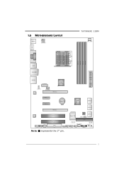
1.5 MOTHERBOARD LAYOUT KBMS 1 ATXPWR1 TA790GXE 128M CPU_ FAN1 HDMI1 S ocket A M 2+ DVI VG A PH1 PH2 PH3 PH4 DIMM A1 DIMM B1 DIMM A2 DIMM B2 USB1 RJ4 5USB1 ATXPWR2 AUDIO2 AUXPWR1 AMD 790GX JUSBV1 L AN SYS_FAN1 PEX16_ 2 PEX1 _1 PEX1 _2 BAT1 AMD SB750 SATA5-6 PEX16_ 1 SATA3-4 Co de c PCI1 Super I/O BI O S JCMOS1 SATA1-2 S PDIF1 F_AUDIO1 CD_IN1 PCI2 FDD1 IDE1 SYS_FA N2 LED_D1 LED_D2 SW_ RST JUSBV 2 F_USB 3 F_USB2 F_USB 1 PANEL1 SW_P WR Note: ■ represents the 1st pin. 5
1.5 MOTHERBOARD LAYOUT KBMS 1 ATXPWR1 TA790GXE 128M CPU_ FAN1 HDMI1 S ocket A M 2+ DVI VG A PH1 PH2 PH3 PH4 DIMM A1 DIMM B1 DIMM A2 DIMM B2 USB1 RJ4 5USB1 ATXPWR2 AUDIO2 AUXPWR1 AMD 790GX JUSBV1 L AN SYS_FAN1 PEX16_ 2 PEX1 _1 PEX1 _2 BAT1 AMD SB750 SATA5-6 PEX16_ 1 SATA3-4 Co de c PCI1 Super I/O BI O S JCMOS1 SATA1-2 S PDIF1 F_AUDIO1 CD_IN1 PCI2 FDD1 IDE1 SYS_FA N2 LED_D1 LED_D2 SW_ RST JUSBV 2 F_USB 3 F_USB2 F_USB 1 PANEL1 SW_P WR Note: ■ represents the 1st pin. 5
Setup Manual
Page 9
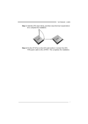
Connect the CPU FAN power cable to complete the installation. This completes the installation. 7 TA790GXE 128M Step 3: Hold the CPU down firmly, and then close the lever toward direct B to the JCFAN1. Step 4: Put the CPU Fan on the CPU and buckle it.
Connect the CPU FAN power cable to complete the installation. This completes the installation. 7 TA790GXE 128M Step 3: Hold the CPU down firmly, and then close the lever toward direct B to the JCFAN1. Step 4: Put the CPU Fan on the CPU and buckle it.
Setup Manual
Page 11
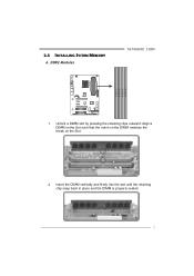
2.3 INSTALLING SYSTEM MEMORY A. Insert the DIMM vertically and firmly into the slot until the retaining chip snap back in place and the DIMM is properly seated. 9 Unlock a DIMM slot by pressing the retaining clips outward. Align a DIMM on the slot such that the notch on the DIMM matches the break on the Slot. 2. DDR2 Modules TA790GXE 128M D IM M A1 D IM M B1 D IM M A2 D IM M B2 1.
2.3 INSTALLING SYSTEM MEMORY A. Insert the DIMM vertically and firmly into the slot until the retaining chip snap back in place and the DIMM is properly seated. 9 Unlock a DIMM slot by pressing the retaining clips outward. Align a DIMM on the slot such that the notch on the DIMM matches the break on the Slot. 2. DDR2 Modules TA790GXE 128M D IM M A1 D IM M B1 D IM M A2 D IM M B2 1.
Setup Manual
Page 13
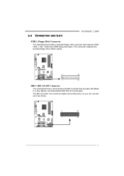
This connector supports the provided floppy drive ribbon cables. 2 34 1 33 IDE1: IDE/ATAPI Connector The motherboard has a 32-bit Enhanced IDE Controller that supports 360K, 720K, 1.2M, 1.44M and 2.88M floppy disk types. 2.4 CONNECTORS AND SLOTS TA790GXE 128M FDD1: Floppy Disk Connector The motherboard provides a standard floppy disk connector that provides PIO Mode 0~4, Bus Master, and Ultra DMA 33/66/100/133 functionality. The IDE connector can connect a master and a slave drive, so you can connect up to two drives. 2 40 1 39 11
This connector supports the provided floppy drive ribbon cables. 2 34 1 33 IDE1: IDE/ATAPI Connector The motherboard has a 32-bit Enhanced IDE Controller that supports 360K, 720K, 1.2M, 1.44M and 2.88M floppy disk types. 2.4 CONNECTORS AND SLOTS TA790GXE 128M FDD1: Floppy Disk Connector The motherboard provides a standard floppy disk connector that provides PIO Mode 0~4, Bus Master, and Ultra DMA 33/66/100/133 functionality. The IDE connector can connect a master and a slave drive, so you can connect up to two drives. 2 40 1 39 11
Setup Manual
Page 15
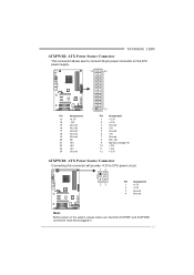
TA790GXE 128M ATXPWR2: ATX Power Source Connector This connector allows user to connect 24-pin power connector on the ATX power supply. 12 24 Pin Assignment 13 +3....
TA790GXE 128M ATXPWR2: ATX Power Source Connector This connector allows user to connect 24-pin power connector on the ATX power supply. 12 24 Pin Assignment 13 +3....
Setup Manual
Page 17
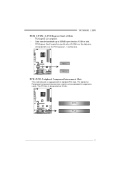
PCI-Express Gen2 supports a raw bit-rate of 5.0Gb/s on the data pins. - 2X bandwidth over the PCI-Express 1.1 architecture. P E X 1_ 1 P E X 1_ 2 PCI1~PCI2: Peripheral Component Interconnect Slots This motherboard is designated as 32 bits. This PCI slot is equipped with 2 standard PCI slots. TA790GXE 128M PEX1_1/PEX1_2: PCI-Express Gen2 x1 Slots - PCI stands for Peripheral Component Interconnect, and it is a bus standard for expansion cards. PCI1 PCI2 15 PCI-Express 2.0 compliant. - Data transfer bandwidth up to 500MB/s per direction; 1GB/s in total. -
PCI-Express Gen2 supports a raw bit-rate of 5.0Gb/s on the data pins. - 2X bandwidth over the PCI-Express 1.1 architecture. P E X 1_ 1 P E X 1_ 2 PCI1~PCI2: Peripheral Component Interconnect Slots This motherboard is designated as 32 bits. This PCI slot is equipped with 2 standard PCI slots. TA790GXE 128M PEX1_1/PEX1_2: PCI-Express Gen2 x1 Slots - PCI stands for Peripheral Component Interconnect, and it is a bus standard for expansion cards. PCI1 PCI2 15 PCI-Express 2.0 compliant. - Data transfer bandwidth up to 500MB/s per direction; 1GB/s in total. -
Setup Manual
Page 19
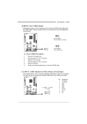
... jumper to "Pin 2-3 close ". 5. Please carefully follow the procedures to restore the BIOS safe setting and the CMOS data. F_USB1~F_USB3: Headers for five seconds. 4. TA790GXE 128M JCMOS1: Clear CMOS Header Placing the jumper on pin2-3 allows user to avoid damaging the motherboard. 13 Pin 1-2 Close: Normal Operation (Default). 1 3 13 Pin 2-3 Close...
... jumper to "Pin 2-3 close ". 5. Please carefully follow the procedures to restore the BIOS safe setting and the CMOS data. F_USB1~F_USB3: Headers for five seconds. 4. TA790GXE 128M JCMOS1: Clear CMOS Header Placing the jumper on pin2-3 allows user to avoid damaging the motherboard. 13 Pin 1-2 Close: Normal Operation (Default). 1 3 13 Pin 2-3 Close...
Setup Manual
Page 21
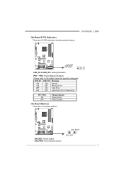
SW_RST 19 PH1~PH4 ON OFF Phase Indicator Phase Active Phase Disable On-Board Buttons There are 6 LED indicators showing system status. SW_PWR: Power Switch button. On-Board LED Indicators There are 2 on-board buttons. SW_PWR SW_RST: Reset button. TA790GXE 128M P H2 P H4 P H1 P H3 LE D_D2 LE D_D1 LED_D1 & LED_D2: Debug Indicators PH1 ~ PH4: Power Status Indicators Please refer to the tables below for specific messages: LED_D1 LED_D2 Message ON ON Normal ON OFF Memory Error OFF ON VGA Error OFF OFF Abnormal: CPU / Chipset error.
SW_RST 19 PH1~PH4 ON OFF Phase Indicator Phase Active Phase Disable On-Board Buttons There are 6 LED indicators showing system status. SW_PWR: Power Switch button. On-Board LED Indicators There are 2 on-board buttons. SW_PWR SW_RST: Reset button. TA790GXE 128M P H2 P H4 P H1 P H3 LE D_D2 LE D_D1 LED_D1 & LED_D2: Debug Indicators PH1 ~ PH4: Power Status Indicators Please refer to the tables below for specific messages: LED_D1 LED_D2 Message ON ON Normal ON OFF Memory Error OFF ON VGA Error OFF OFF Abnormal: CPU / Chipset error.
Setup Manual
Page 23
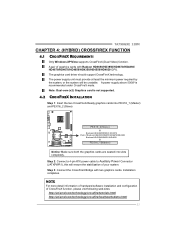
...: Dual-core (x2) Graphics card is recommended under CrossFireX mode. Step 2: Connect a 4-pin ATX power cable to Auxiliary Power Connector (JATXPWR1), this will be unstable. TA790GXE 128M CHAPTER 4: (HYBRID) CROSSFIREX FUNCTION 4.1 CROSSFIREX REQUIREMENTS Only Windows XP/Vista supports CrossFireX (Dual Video) function. The graphics card driver should support CrossFireX technology. Installation completes...
...: Dual-core (x2) Graphics card is recommended under CrossFireX mode. Step 2: Connect a 4-pin ATX power cable to Auxiliary Power Connector (JATXPWR1), this will be unstable. TA790GXE 128M CHAPTER 4: (HYBRID) CROSSFIREX FUNCTION 4.1 CROSSFIREX REQUIREMENTS Only Windows XP/Vista supports CrossFireX (Dual Video) function. The graphics card driver should support CrossFireX technology. Installation completes...
Setup Manual
Page 25
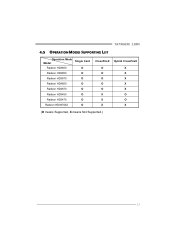
TA790GXE 128M 4.5 OPERATION MODES SUPPORTING LIST Operation Mode Single Card Model Radeon HD3650 O Radeon HD3850 O Radeon HD3870 O Radeon HD4850 O Radeon HD4870 O Radeon HD3450 O Radeon HD3470 O Radeon HD3870X2 O CrossFireX Hybrid CrossFireX O X O X O X O X O X X O X O X X (O means Supported, X means Not Supported.) 23
TA790GXE 128M 4.5 OPERATION MODES SUPPORTING LIST Operation Mode Single Card Model Radeon HD3650 O Radeon HD3850 O Radeon HD3870 O Radeon HD4850 O Radeon HD4870 O Radeon HD3450 O Radeon HD3470 O Radeon HD3870X2 O CrossFireX Hybrid CrossFireX O X O X O X O X O X X O X O X X (O means Supported, X means Not Supported.) 23
Setup Manual
Page 27
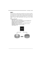
TA790GXE 128M RAID 1: Every read and write is impaired during drive rebuilds. Fault Tolerance: Yes. RAID techniques can reside on the same disk or on a second ...
TA790GXE 128M RAID 1: Every read and write is impaired during drive rebuilds. Fault Tolerance: Yes. RAID techniques can reside on the same disk or on a second ...
Setup Manual
Page 29
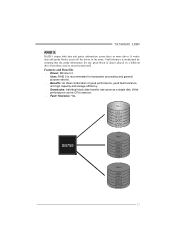
... DATA 5 DATA 8 PARITY DATA 11 Disk 3 PARITY DATA 4 DATA 6 PARITY DATA 10 DATA 12 27 Write performance can be CPU intensive. Fault Tolerance: Yes. TA790GXE 128M RAID 5: RAID 5 stripes both data and parity information across all the drives in the array. It writes data and parity blocks across three or more...
... DATA 5 DATA 8 PARITY DATA 11 Disk 3 PARITY DATA 4 DATA 6 PARITY DATA 10 DATA 12 27 Write performance can be CPU intensive. Fault Tolerance: Yes. TA790GXE 128M RAID 5: RAID 5 stripes both data and parity information across all the drives in the array. It writes data and parity blocks across three or more...
Setup Manual
Page 31
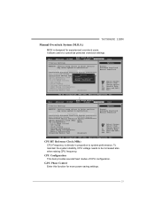
... increased also when raising CPU frequency. Change Option F1 General Help F10 Save and Exit ESC Exit vxx.xx (C)Copyright 1985-200x, American Megatrends, Inc. TA790GXE 128M Manual Overclock System (M.O.S.) MOS is directly in proportion to system performance. G.P.U Phase Control Enter this function for experienced overclock users. To maintain the system stability...
... increased also when raising CPU frequency. Change Option F1 General Help F10 Save and Exit ESC Exit vxx.xx (C)Copyright 1985-200x, American Megatrends, Inc. TA790GXE 128M Manual Overclock System (M.O.S.) MOS is directly in proportion to system performance. G.P.U Phase Control Enter this function for experienced overclock users. To maintain the system stability...
Setup Manual
Page 33
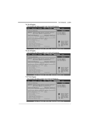
... malfunction. Main Advanced PCIPnP BIOS SETUP UTILITY Boot Chipset T-Series Exit T-Series Settings WARNING: Setting wrong values in below sections may cause system to malfunction. TA790GXE 128M V6 Tech Engine This engine will make a good over -clock performance. Main Advanced PCIPnP BIOS SETUP UTILITY Boot Chipset T-Series Exit T-Series Settings WARNING: Setting...
... malfunction. Main Advanced PCIPnP BIOS SETUP UTILITY Boot Chipset T-Series Exit T-Series Settings WARNING: Setting wrong values in below sections may cause system to malfunction. TA790GXE 128M V6 Tech Engine This engine will make a good over -clock performance. Main Advanced PCIPnP BIOS SETUP UTILITY Boot Chipset T-Series Exit T-Series Settings WARNING: Setting...
Setup Manual
Page 35
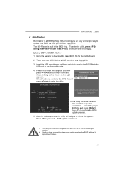
... utility will lead to reboot the system. To enter the utility, press during the POST process. z This utility only allows storage device with BIO-Flasher 1. TA790GXE 128M C.
... utility will lead to reboot the system. To enter the utility, press during the POST process. z This utility only allows storage device with BIO-Flasher 1. TA790GXE 128M C.
Setup Manual
Page 37
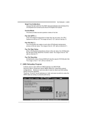
TA790GXE 128M Smart Fan Calibration Choose this set value. F. Fan Ctrl Sensitive Increasing the value of slope PWM will turn off. Users are able to save different ...
TA790GXE 128M Smart Fan Calibration Choose this set value. F. Fan Ctrl Sensitive Increasing the value of slope PWM will turn off. Users are able to save different ...
Setup Manual
Page 39
Over Clock Panel Restore Default Settings AUTO Over-Clock V3/V6/V9 Engine Real-time Ove r-clock TA790GXE 128M Manual Adjust CPU Clock Test & Apply Manual Setting s AUTO User can click this button and the utility will show up to notify you that the system may become unstable, click on "OK" to continue. 37 A warning dialog as below will set the best and stable performance and frequency automatically.
Over Clock Panel Restore Default Settings AUTO Over-Clock V3/V6/V9 Engine Real-time Ove r-clock TA790GXE 128M Manual Adjust CPU Clock Test & Apply Manual Setting s AUTO User can click this button and the utility will show up to notify you that the system may become unstable, click on "OK" to continue. 37 A warning dialog as below will set the best and stable performance and frequency automatically.
Setup Manual
Page 41
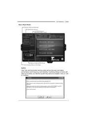
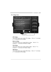
... CPU voltage. Click on "+" to increase or "-" to decrease the Chipset voltage. Chip Voltage This function allows user to adjust CPU voltage. Over Voltage Panel TA790GXE 128M Manual Adjust CPU/Memo ry/Chipset/FSB Voltage CPU Voltage This function allows user to adjust Chipset voltage.
... CPU voltage. Click on "+" to increase or "-" to decrease the Chipset voltage. Chip Voltage This function allows user to adjust CPU voltage. Over Voltage Panel TA790GXE 128M Manual Adjust CPU/Memo ry/Chipset/FSB Voltage CPU Voltage This function allows user to adjust Chipset voltage.