Bios Setup
Page 2
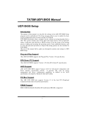
...devices such as keyboard, mouse, serial ports and disk drives. PCI Bus Support This AMI UEFI BIOS also supports Version 2.3 of this motherboard. The rest of the Intel PCI (Peripheral Component Interconnect) local bus specification. ACPI Support AMI ACPI UEFI BIOS support Version 1.0/2.0 of this...such as defined in UEFI BIOS. Plug and Play Support This AMI UEFI BIOS supports the Plug and Play Version 1.0A specification. TA75M UEFI BIOS Manual UEFI BIOS Setup Introduction The purpose of Advanced Configuration and Power interface specification (ACPI). BIOS activates at the first ...
...devices such as keyboard, mouse, serial ports and disk drives. PCI Bus Support This AMI UEFI BIOS also supports Version 2.3 of this motherboard. The rest of the Intel PCI (Peripheral Component Interconnect) local bus specification. ACPI Support AMI ACPI UEFI BIOS support Version 1.0/2.0 of this...such as defined in UEFI BIOS. Plug and Play Support This AMI UEFI BIOS supports the Plug and Play Version 1.0A specification. TA75M UEFI BIOS Manual UEFI BIOS Setup Introduction The purpose of Advanced Configuration and Power interface specification (ACPI). BIOS activates at the first ...
Bios Setup
Page 3
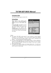
..., and this manual is being continuously updated. In the UEFI BIOS setup utility, you can use these keys to enter the UEFI BIOS setup utility. TA75M UEFI BIOS Manual Supported CPUs This AMI UEFI BIOS supports the Intel CPU. If the system becomes unstable after changing any mistakes found in this...
..., and this manual is being continuously updated. In the UEFI BIOS setup utility, you can use these keys to enter the UEFI BIOS setup utility. TA75M UEFI BIOS Manual Supported CPUs This AMI UEFI BIOS supports the Intel CPU. If the system becomes unstable after changing any mistakes found in this...
Setup Manual
Page 2
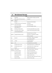
Table of Contents Chapter 1: Introduction 1 1.1 Before You Start 1 1.2 Package Checklist 1 1.3 Motherboard Features 2 1.4 Rear Panel Connectors 3 1.5 Motherboard Layout 4 Chapter 2: Hardware Installation 5 2.1 Installing Central Processing Unit (CPU 5 2.2 FAN Headers 7 2.3 Installing System Memory 8 2.4 Connectors and Slots 10 Chapter 3: Headers & Jumpers Setup 13 3.1 How to ...
Table of Contents Chapter 1: Introduction 1 1.1 Before You Start 1 1.2 Package Checklist 1 1.3 Motherboard Features 2 1.4 Rear Panel Connectors 3 1.5 Motherboard Layout 4 Chapter 2: Hardware Installation 5 2.1 Installing Central Processing Unit (CPU 5 2.2 FAN Headers 7 2.3 Installing System Memory 8 2.4 Connectors and Slots 10 Chapter 3: Headers & Jumpers Setup 13 3.1 How to ...

Setup Manual
Page 3
...anti-static bag, ground yourself properly by touching any unfastened small parts inside the case after installation. CHAPTER 1: INTRODUCTION TA75M 1.1 BEFORE YOU START Thank you take the motherboard out from dangerous area, such as heat source, humid air and water. „ The operating temperatures of the computer...try to bend or flex the board. „ Do not leave any safely grounded appliance, or use grounded wrist strap to area or your motherboard version. 1 Loose parts will cause short circuits which may be 0 to 45 degrees Celsius. 1.2 PACKAGE CHECKLIST Serial ATA Cable X4 Rear ...
...anti-static bag, ground yourself properly by touching any unfastened small parts inside the case after installation. CHAPTER 1: INTRODUCTION TA75M 1.1 BEFORE YOU START Thank you take the motherboard out from dangerous area, such as heat source, humid air and water. „ The operating temperatures of the computer...try to bend or flex the board. „ Do not leave any safely grounded appliance, or use grounded wrist strap to area or your motherboard version. 1 Loose parts will cause short circuits which may be 0 to 45 degrees Celsius. 1.2 PACKAGE CHECKLIST Serial ATA Cable X4 Rear ...
Setup Manual
Page 4
SATA III Integrated Serial ATA Controller SATA Version 3.0 specification compliant. Motherboard Manual 1.3 MOTHERBOARD FEATURES SPEC Socket FM1 AMD 64 Architecture enables 32 and 64 bit CPU AMD A-Series / E2-Series processors computing Chipset AMD A75 ITE 8728 Provides ...
SATA III Integrated Serial ATA Controller SATA Version 3.0 specification compliant. Motherboard Manual 1.3 MOTHERBOARD FEATURES SPEC Socket FM1 AMD 64 Architecture enables 32 and 64 bit CPU AMD A-Series / E2-Series processors computing Chipset AMD A75 ITE 8728 Provides ...

Setup Manual
Page 6
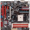
Motherboard Manual 1.5 MOTHERBOARD LAYOUT USB_KBMS1 CP U_FAN 1 NB_ P H1_ D1 P H1_ D1 P H3_ D3 P H2_ D2 H DMI1 ATXPWR2 DVI1 DDR3_ A 1 DDR3_ A 2 DDR3_ B 1 DDR3_ B 2 VGA1 ATX PW R 1 R J45U SB1 LAN BIOS A UDI O1 J SP DI FO UT1 SYS_FAN2 PEX16_1 Super I/O PEX1_1 BAT1 PEX16_2 AMD A75 S ATA 2 S ATA 1 C odec F_ AU DIO1 J_ PR IN T1 PCI1 J_C OM1 JC MOS 1 LED_D1 LED_D2 SW _ PWR 1 S ATA4 C IR 1 F_U SB 1 F_USB 2 JFR ON T_U SB 3_1 PA NE L1 SW_RST1 S ATA3 SY S_FA N1 Note: ■ represents the 1st pin. 4
Motherboard Manual 1.5 MOTHERBOARD LAYOUT USB_KBMS1 CP U_FAN 1 NB_ P H1_ D1 P H1_ D1 P H3_ D3 P H2_ D2 H DMI1 ATXPWR2 DVI1 DDR3_ A 1 DDR3_ A 2 DDR3_ B 1 DDR3_ B 2 VGA1 ATX PW R 1 R J45U SB1 LAN BIOS A UDI O1 J SP DI FO UT1 SYS_FAN2 PEX16_1 Super I/O PEX1_1 BAT1 PEX16_2 AMD A75 S ATA 2 S ATA 1 C odec F_ AU DIO1 J_ PR IN T1 PCI1 J_C OM1 JC MOS 1 LED_D1 LED_D2 SW _ PWR 1 S ATA4 C IR 1 F_U SB 1 F_USB 2 JFR ON T_U SB 3_1 PA NE L1 SW_RST1 S ATA3 SY S_FA N1 Note: ■ represents the 1st pin. 4
Setup Manual
Page 8
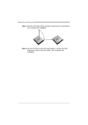
Step 4: Put the CPU Fan on the CPU and buckle it. This completes the installation. 6 Connect the CPU FAN power cable to complete the installation. Motherboard Manual Step 3: Hold the CPU down firmly, and then close the lever toward direct B to the CPU_FAN1.
Step 4: Put the CPU Fan on the CPU and buckle it. This completes the installation. 6 Connect the CPU FAN power cable to complete the installation. Motherboard Manual Step 3: Hold the CPU down firmly, and then close the lever toward direct B to the CPU_FAN1.

Setup Manual
Page 10
Align a DIMM on the slot such that the notch on the DIMM matches the break on the Slot. 2. Insert the DIMM vertically and firmly into the slot until the retaining chip snap back in place and the DIMM is properly seated. 8 DDR 3_A1 DDR 3_A2 DDR 3_B1 DDR 3_B2 Motherboard Manual 2.3 INSTALLING SYSTEM MEMORY A. DDR3 Modules 1. Unlock a DIMM slot by pressing the retaining clips outward.
Align a DIMM on the slot such that the notch on the DIMM matches the break on the Slot. 2. Insert the DIMM vertically and firmly into the slot until the retaining chip snap back in place and the DIMM is properly seated. 8 DDR 3_A1 DDR 3_A2 DDR 3_B1 DDR 3_B2 Motherboard Manual 2.3 INSTALLING SYSTEM MEMORY A. DDR3 Modules 1. Unlock a DIMM slot by pressing the retaining clips outward.
Setup Manual
Page 12
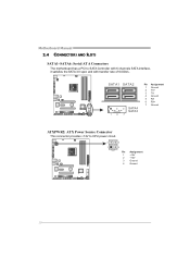
Motherboard Manual 2.4 CONNECTORS AND SLOTS SATA1~SATA6: Serial ATA Connectors The motherboard has a PCI to CPU power circuit. 4 3 1 2 Pin Assignment 1 +12V 2 +12V 3 Ground 4 Ground 10 SATA1 SATA2 S ATA4 S ATA3 14 7 Pin Assignment 1 Ground 2 TX+ 3 TX4 Ground 5 RX6 RX+ 7 Ground ATXPWR2: ATX Power Source Connector This connector provides +12V to SATA Controller with 6 channels SATA interface, it satisfies the SATA 3.0 spec and with transfer rate of 6.0Gb/s.
Motherboard Manual 2.4 CONNECTORS AND SLOTS SATA1~SATA6: Serial ATA Connectors The motherboard has a PCI to CPU power circuit. 4 3 1 2 Pin Assignment 1 +12V 2 +12V 3 Ground 4 Ground 10 SATA1 SATA2 S ATA4 S ATA3 14 7 Pin Assignment 1 Ground 2 TX+ 3 TX4 Ground 5 RX6 RX+ 7 Ground ATXPWR2: ATX Power Source Connector This connector provides +12V to SATA Controller with 6 channels SATA interface, it satisfies the SATA 3.0 spec and with transfer rate of 6.0Gb/s.

Setup Manual
Page 13
PCI stands for Peripheral Component Interconnect, and it is designated as 32 bits. TA75M ATXPWR1: ATX Power Source Connector This connector allows user to connect 24-pin power connector on the ATX power supply. 12 24 1 13 Pin 13 ... that both ATXPWR1 and ATXPWR2 connectors have been plugged-in. This PCI slot is a bus standard for expansion cards. PCI1: Peripheral Component Interconnect Slot This motherboard is equipped with 1 standard PCI slot. PCI1 11
PCI stands for Peripheral Component Interconnect, and it is designated as 32 bits. TA75M ATXPWR1: ATX Power Source Connector This connector allows user to connect 24-pin power connector on the ATX power supply. 12 24 1 13 Pin 13 ... that both ATXPWR1 and ATXPWR2 connectors have been plugged-in. This PCI slot is a bus standard for expansion cards. PCI1: Peripheral Component Interconnect Slot This motherboard is equipped with 1 standard PCI slot. PCI1 11

Setup Manual
Page 14
... 2GB/s per direction; 1GB/s in total. - PCI-Express 2.0 compliant. - PEX16_2: PCI-Express Gen2 x4 Slot - PCI-Express Gen2 supports a raw bit-rate of 16GB/s totally. - Motherboard Manual PEX16_1: PCI-Express Gen2 x16 Slot - PCI-Express 2.0 compliant. - Data transfer bandwidth up to 500MB/s per direction; 4GB/s in total. -
... 2GB/s per direction; 1GB/s in total. - PCI-Express 2.0 compliant. - PEX16_2: PCI-Express Gen2 x4 Slot - PCI-Express Gen2 supports a raw bit-rate of 16GB/s totally. - Motherboard Manual PEX16_1: PCI-Express Gen2 x16 Slot - PCI-Express 2.0 compliant. - Data transfer bandwidth up to 500MB/s per direction; 4GB/s in total. -
Setup Manual
Page 16
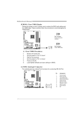
J_COM1: Serial port Connector The motherboard has a Serial Port Connector for five seconds. 4. Wait for connecting RS-232 Port. 2 10 1 9 Pin Assignment 1 Carrier detect 2 Received data 3 Transmitted data 4 Data terminal ready 5...save settings in CMOS. Set the jumper to "Pin 2-3 close ". 5. Set the jumper to "Pin 1-2 close ". 3. Power on pin2-3 allows user to avoid damaging the motherboard. 31 Pin 1-2 Close: Normal Operation (default). 31 31 Pin 2-3 Close: Clear CMOS data. ※ Clear CMOS Procedures: 1. Please carefully follow the procedures to restore the...
J_COM1: Serial port Connector The motherboard has a Serial Port Connector for five seconds. 4. Wait for connecting RS-232 Port. 2 10 1 9 Pin Assignment 1 Carrier detect 2 Received data 3 Transmitted data 4 Data terminal ready 5...save settings in CMOS. Set the jumper to "Pin 2-3 close ". 5. Set the jumper to "Pin 1-2 close ". 3. Power on pin2-3 allows user to avoid damaging the motherboard. 31 Pin 1-2 Close: Normal Operation (default). 31 31 Pin 2-3 Close: Clear CMOS data. ※ Clear CMOS Procedures: 1. Please carefully follow the procedures to restore the...

Setup Manual
Page 18
Motherboard Manual CIR1: Consumer IR Connector This header is for infrared remote control and communication. 26 15 Pin Assignment 1 IrDA serial input 2 Ground 3 Ground 4 Key 5 IrDA ...
Motherboard Manual CIR1: Consumer IR Connector This header is for infrared remote control and communication. 26 15 Pin Assignment 1 IrDA serial input 2 Ground 3 Ground 4 Key 5 IrDA ...

Setup Manual
Page 20
... tables below for specific messages: LED_D1 LED_D2 Message ON ON Normal ON OFF Memory Error OFF OFF ON VGA Error OFF Abnormal: CPU / Chipset error. Motherboard Manual On-Board LED Indicators There are 2 on-board buttons.
... tables below for specific messages: LED_D1 LED_D2 Message ON ON Normal ON OFF Memory Error OFF OFF ON VGA Error OFF Abnormal: CPU / Chipset error. Motherboard Manual On-Board LED Indicators There are 2 on-board buttons.
Setup Manual
Page 22
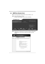
Step 2: Set the BIOS setting as follows: [Chipset]→[North Bridge]→[Surround View]→[Enabled] Step 3: Install Driver CD Chipset Driver, and reboot the system. Motherboard Manual 4.3 AMD DUAL GRAPHICS SETUP Step 1: Insert Dual Graphics-Ready graphics card into PEX16_1 slot. Activate AMD VISION Engine Control Center to make sure CrossFire has been enabled. 20
Step 2: Set the BIOS setting as follows: [Chipset]→[North Bridge]→[Surround View]→[Enabled] Step 3: Install Driver CD Chipset Driver, and reboot the system. Motherboard Manual 4.3 AMD DUAL GRAPHICS SETUP Step 1: Insert Dual Graphics-Ready graphics card into PEX16_1 slot. Activate AMD VISION Engine Control Center to make sure CrossFire has been enabled. 20

Setup Manual
Page 24
...% data redundancy. Should one drive fail, the controller switches to the other application that eliminates tedious manual backups to more expensive and less reliable media. Motherboard Manual RAID 1: Every read and write is impaired during drive rebuilds. Fault Tolerance: Yes. Block 1 Block 2 Block 3 Block 1 Block 2 Block 3 22 Performance is actually...
...% data redundancy. Should one drive fail, the controller switches to the other application that eliminates tedious manual backups to more expensive and less reliable media. Motherboard Manual RAID 1: Every read and write is impaired during drive rebuilds. Fault Tolerance: Yes. Block 1 Block 2 Block 3 Block 1 Block 2 Block 3 22 Performance is actually...
Setup Manual
Page 26
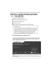
... of setting up the UEFI BIOS, please refer to customize personal overclock settings: Manual Voltage System, Manual Memory System, Manual MCT System, and Manual G.P.U System. Motherboard Manual CHAPTER 6: T-SERIES UEFI BIOS & SOFTWARE 6.1 T-SERIES UEFI BIOS T-Series UEFI BIOS Features Overclocking Navigator Engine (O.N.E.) Self Recovery System (S.R.S) Smart Fan Function BIO-Flasher: Update...
... of setting up the UEFI BIOS, please refer to customize personal overclock settings: Manual Voltage System, Manual Memory System, Manual MCT System, and Manual G.P.U System. Motherboard Manual CHAPTER 6: T-SERIES UEFI BIOS & SOFTWARE 6.1 T-SERIES UEFI BIOS T-Series UEFI BIOS Features Overclocking Navigator Engine (O.N.E.) Self Recovery System (S.R.S) Smart Fan Function BIO-Flasher: Update...

Setup Manual
Page 28
... lowest RPM. The range is from 0~127, with an interval of the fan. The range is from 0~127, with an interval of 1. The range is . Motherboard Manual CPU Smart FAN This item allows you to calibrate CPU FAN.
... lowest RPM. The range is from 0~127, with an interval of the fan. The range is from 0~127, with an interval of 1. The range is . Motherboard Manual CPU Smart FAN This item allows you to calibrate CPU FAN.

Setup Manual
Page 30
It also provides six pre-set modes for reference only) 28 The OC Tweaker tab allows you : (The screenshot below is for you to see its information. You can select memory module on the CPU and motherboard. Motherboard Manual The CPU tab provides information on a specific slot to change system clock settings and voltages settings. The Memory tab provides information on the memory module(s).
It also provides six pre-set modes for reference only) 28 The OC Tweaker tab allows you : (The screenshot below is for you to see its information. You can select memory module on the CPU and motherboard. Motherboard Manual The CPU tab provides information on a specific slot to change system clock settings and voltages settings. The Memory tab provides information on the memory module(s).
Setup Manual
Page 32
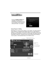
.... (The illustration below is a new function. it optimizes power saving and best power efficiency on light loading; Motherboard Manual Pressing TOVERCLOCKER logo will display information about manufacturer and software version. Green Power II Utility BIOSTAR G.P.U II (Green Power Utility) is for reference only) Display manufacturer & Typical Mode software version information Performance M ode...
.... (The illustration below is a new function. it optimizes power saving and best power efficiency on light loading; Motherboard Manual Pressing TOVERCLOCKER logo will display information about manufacturer and software version. Green Power II Utility BIOSTAR G.P.U II (Green Power Utility) is for reference only) Display manufacturer & Typical Mode software version information Performance M ode...


