Setup Manual
Page 2
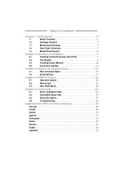
Table of Contents Chapter 1: Introduction 3 1.1 Before You Start 3 1.2 Package Checklist 3 1.3 Motherboard Features 4 1.4 Rear Panel Connectors 5 1.5 Motherboard Layout 6 Chapter 2: Hardware Installation 7 2.1 Installing Central Processing Unit (CPU 7 2.2 Fan Headers 9 2.3 Installing System Memory 10 2.4 Connectors and Slots 12 Chapter 3: Headers & Jumpers Setup 14 3.1 How to Setup Jumpers 14 3.2 Detail Settings 14 Chapter 4: RAID ...
Table of Contents Chapter 1: Introduction 3 1.1 Before You Start 3 1.2 Package Checklist 3 1.3 Motherboard Features 4 1.4 Rear Panel Connectors 5 1.5 Motherboard Layout 6 Chapter 2: Hardware Installation 7 2.1 Installing Central Processing Unit (CPU 7 2.2 Fan Headers 9 2.3 Installing System Memory 10 2.4 Connectors and Slots 12 Chapter 3: Headers & Jumpers Setup 14 3.1 How to Setup Jumpers 14 3.2 Detail Settings 14 Chapter 4: RAID ...
Setup Manual
Page 4
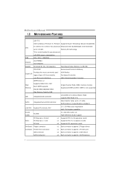
... nt. Motherboard Manual 1.3 MOT HERBOARD FEAT URES SPEC LGA 775 Intel Core2Duo/ Pe ntium 4 / Pentium Supports Hy per Thre ading/ Execute Disable Bit/ CPU D / Celero n D / C eleron 4xx processor Enha nced Intel SpeedStep®/ Intel Extended up to use processors with 95W power consumption. FSB 533 .../ 800 / 1066 MHz Chipset Graphic VIA P4M900 VIA VT8237A Chrome9 HC 3D / 2D Graphics Max Share d Vide o Memory is 256 MB ITE 8712F Provides the most commonly used Super...
... nt. Motherboard Manual 1.3 MOT HERBOARD FEAT URES SPEC LGA 775 Intel Core2Duo/ Pe ntium 4 / Pentium Supports Hy per Thre ading/ Execute Disable Bit/ CPU D / Celero n D / C eleron 4xx processor Enha nced Intel SpeedStep®/ Intel Extended up to use processors with 95W power consumption. FSB 533 .../ 800 / 1066 MHz Chipset Graphic VIA P4M900 VIA VT8237A Chrome9 HC 3D / 2D Graphics Max Share d Vide o Memory is 256 MB ITE 8712F Provides the most commonly used Super...
Setup Manual
Page 5
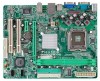
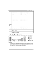
... Connects to RJ- 45 ether net cable x4 Connects to USB devices x3 Provide Audio-In/Out a nd microphone co nnection Micro ATX Size Board Biostar Reserves the right to a dd or r emove support for any OS with Smart Fa n function) x1 System Fan Power supply x1 Restore CMOS ...190 mm (W) x 244 mm (L) Special Feature RAID 0 / 1 support OS Support Windows 2000 / XP / VISTA P4M900-M7 FE SPEC x1 Supports front panel facilities x1 Supports front panel a udio function x1 Supports CD audio-in function x1 CPU Fan power s upply (with or witho ut notice. 1.4 REAR PANEL CONNECT ORS PS /2 Mouse LA N Li...
... Connects to RJ- 45 ether net cable x4 Connects to USB devices x3 Provide Audio-In/Out a nd microphone co nnection Micro ATX Size Board Biostar Reserves the right to a dd or r emove support for any OS with Smart Fa n function) x1 System Fan Power supply x1 Restore CMOS ...190 mm (W) x 244 mm (L) Special Feature RAID 0 / 1 support OS Support Windows 2000 / XP / VISTA P4M900-M7 FE SPEC x1 Supports front panel facilities x1 Supports front panel a udio function x1 Supports CD audio-in function x1 CPU Fan power s upply (with or witho ut notice. 1.4 REAR PANEL CONNECT ORS PS /2 Mouse LA N Li...
Setup Manual
Page 7
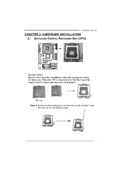
Pin Cap Step 1: Pull the socket locking lever out from the socket and then raise the lever up to ensure pin legs won't be damaged. When the CPU is removed, cover the Pin Cap on the empty socket to a 90-degree angle. 7 P4M900-M7 FE CHAPTER 2: HARDWARE INSTALLATION 2.1 INST ALLING CENT RAL PROCESSING UNIT (CPU) Special Notice: Remove Pin Cap before installation, and make good preservation for future use.
Pin Cap Step 1: Pull the socket locking lever out from the socket and then raise the lever up to ensure pin legs won't be damaged. When the CPU is removed, cover the Pin Cap on the empty socket to a 90-degree angle. 7 P4M900-M7 FE CHAPTER 2: HARDWARE INSTALLATION 2.1 INST ALLING CENT RAL PROCESSING UNIT (CPU) Special Notice: Remove Pin Cap before installation, and make good preservation for future use.
Setup Manual
Page 8
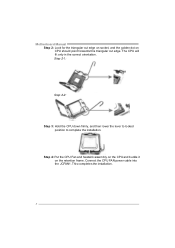
Connect the CPU FAN power cable into the JCFAN1. Motherboard Manual Step 2: Look for the triangular cut edge on socket, and the golden dot on the retention frame. The CPU will fit only in the correct orientation. Step 4: Put the CPU Fan and heatsink assembly on the CPU and buckle it on CPU should point forwards this triangular cut edge. This completes the installation. 8 Step 2-1: Step 2-2: Step 3: Hold the CPU down firmly, and then lower the lever to locked position to complete the installation.
Connect the CPU FAN power cable into the JCFAN1. Motherboard Manual Step 2: Look for the triangular cut edge on socket, and the golden dot on the retention frame. The CPU will fit only in the correct orientation. Step 4: Put the CPU Fan and heatsink assembly on the CPU and buckle it on CPU should point forwards this triangular cut edge. This completes the installation. 8 Step 2-1: Step 2-2: Step 3: Hold the CPU down firmly, and then lower the lever to locked position to complete the installation.
Setup Manual
Page 15
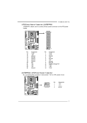
Pin Assignment 1 4 1 +12V 2 +12V 2 3 3 Ground 4 Ground 15 P4M900-M7 FE ATX Powe r Source Conne ctor: JATXPWR1 JATXPWR1 allows user to connect 24-pin power connector on the ATX power supply. 12 24 Pin Assignment 13 +3.... 7 Ground 8 PW_OK 9 StandbyVoltage+5V 10 +12V 11 +12V 12 +3.3V JATXPWR2: ATX Powe r Source C onne ctor By connecting this connector, it will provide +12V to CPU power circuit.
Pin Assignment 1 4 1 +12V 2 +12V 2 3 3 Ground 4 Ground 15 P4M900-M7 FE ATX Powe r Source Conne ctor: JATXPWR1 JATXPWR1 allows user to connect 24-pin power connector on the ATX power supply. 12 24 Pin Assignment 13 +3.... 7 Ground 8 PW_OK 9 StandbyVoltage+5V 10 +12V 11 +12V 12 +3.3V JATXPWR2: ATX Powe r Source C onne ctor By connecting this connector, it will provide +12V to CPU power circuit.
Setup Manual
Page 23
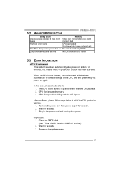
... beeps every other second No DRAM detected or install 5.3 EXT RA INFORMAT ION CPU Overheated If the system shutdown automatically after power on the system again. 23 5.2 AWARD BIOS BEEP CODE P4M900-M7 FE Beep Sound One long beep followed by two short beeps Meaning Video card not ...found or v ideo card memory bad High-low siren sound CPU overheated System will shutdown automatically to relief the CPU protection function. 1. The CPU cooler surface is rotated normally....
... beeps every other second No DRAM detected or install 5.3 EXT RA INFORMAT ION CPU Overheated If the system shutdown automatically after power on the system again. 23 5.2 AWARD BIOS BEEP CODE P4M900-M7 FE Beep Sound One long beep followed by two short beeps Meaning Video card not ...found or v ideo card memory bad High-low siren sound CPU overheated System will shutdown automatically to relief the CPU protection function. 1. The CPU cooler surface is rotated normally....


