Setup Manual
Page 2
Table of Contents Chapter 1: Introduction 3 1.1 Before You Start 3 1.2 Package Checklist 3 1.3 Motherboard Features 4 1.4 Rear Panel Connectors 5 1.5 Motherboard Layout 6 Chapter 2: Hardware Installation 7 2.1 Installing Central Processing Unit (CPU 7 2.2 Fan Headers 9 2.3 Installing System Memory 10 2.4 Connectors and Slots 12 Chapter 3: Headers & Jumpers Setup 14 3.1 How ...
Table of Contents Chapter 1: Introduction 3 1.1 Before You Start 3 1.2 Package Checklist 3 1.3 Motherboard Features 4 1.4 Rear Panel Connectors 5 1.5 Motherboard Layout 6 Chapter 2: Hardware Installation 7 2.1 Installing Central Processing Unit (CPU 7 2.2 Fan Headers 9 2.3 Installing System Memory 10 2.4 Connectors and Slots 12 Chapter 3: Headers & Jumpers Setup 14 3.1 How ...
Setup Manual
Page 3
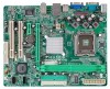
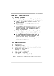
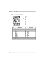
P4M900-M7 FE CHAPTER 1: INTRODUCTION 1.1 BEFORE YOU START Thank you for ATX Case X 1 FDD Cable X 1 (optional) Se rial ATA Cable X 1 (optional) USB 2.0 Cable X1 (optional) Se rial ATA ...) Note: The package contents may damage the equipment. „ Keep the compute r from anti-static bag, ground yourse lf prope rly by area or your motherboard version. 3 Loose parts will cause short circuits which may differ by touching any safe ly grounde d appliance, or use grounded wrist strap to remove the...
P4M900-M7 FE CHAPTER 1: INTRODUCTION 1.1 BEFORE YOU START Thank you for ATX Case X 1 FDD Cable X 1 (optional) Se rial ATA Cable X 1 (optional) USB 2.0 Cable X1 (optional) Se rial ATA ...) Note: The package contents may damage the equipment. „ Keep the compute r from anti-static bag, ground yourse lf prope rly by area or your motherboard version. 3 Loose parts will cause short circuits which may differ by touching any safe ly grounde d appliance, or use grounded wrist strap to remove the...
Setup Manual
Page 4
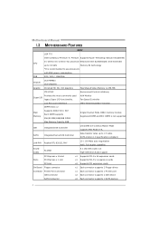
... Half / Full duplex capability Sound Codec ALC662 5.1 cha nnels a udio o ut High- FSB 533 / 800 / 1066 MHz Chipset Graphic VIA P4M900 VIA VT8237A Chrome9 HC 3D / 2D Graphics Max Share d Vide o Memory is 256 MB ITE 8712F Provides the most commonly used Super I/O legacy...DIMM and ECC DIMM is not supported IDE Integrated I /O functionality. E x 16 expa nsion cards x1 Supports PCI- SATA Version 1.0 specification complia nt. Motherboard Manual 1.3 MOT HERBOARD FEAT URES SPEC LGA 775 Intel Core2Duo/ Pe ntium 4 / Pentium Supports Hy per Thre ading/ Execute Disable Bit/ CPU D /...
... Half / Full duplex capability Sound Codec ALC662 5.1 cha nnels a udio o ut High- FSB 533 / 800 / 1066 MHz Chipset Graphic VIA P4M900 VIA VT8237A Chrome9 HC 3D / 2D Graphics Max Share d Vide o Memory is 256 MB ITE 8712F Provides the most commonly used Super I/O legacy...DIMM and ECC DIMM is not supported IDE Integrated I /O functionality. E x 16 expa nsion cards x1 Supports PCI- SATA Version 1.0 specification complia nt. Motherboard Manual 1.3 MOT HERBOARD FEAT URES SPEC LGA 775 Intel Core2Duo/ Pe ntium 4 / Pentium Supports Hy per Thre ading/ Execute Disable Bit/ CPU D /...
Setup Manual
Page 6
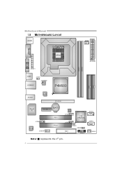
Motherboard Manual 1.5 MOT HERBOARD LAYOUT JKB MS1 LGA775 JCFAN1 COJMC1OM1 CPU1 JATXPWR1 JVGA1 DIMM1 DIMM2 JPRNT1 JUSB1 JUSBV1 JATXPWR2 J US BLAN1 P4M900 IDE1 IDE2 JAUDIO1 LAN PCI-E X16 Super I/O BAT1 PCI-EX1_1 JCDIN1 Codec JAUDIOF1 PCI1 PCI2 BIOS JU SB2 VIA VT8237A JUSB3 FDD1 JUSBV2 JCMOS1 JPAN EL 1 JSATA2 JSATA1 JSFAN1 Not e: ■ represe nts the 1st pin. 6
Motherboard Manual 1.5 MOT HERBOARD LAYOUT JKB MS1 LGA775 JCFAN1 COJMC1OM1 CPU1 JATXPWR1 JVGA1 DIMM1 DIMM2 JPRNT1 JUSB1 JUSBV1 JATXPWR2 J US BLAN1 P4M900 IDE1 IDE2 JAUDIO1 LAN PCI-E X16 Super I/O BAT1 PCI-EX1_1 JCDIN1 Codec JAUDIOF1 PCI1 PCI2 BIOS JU SB2 VIA VT8237A JUSB3 FDD1 JUSBV2 JCMOS1 JPAN EL 1 JSATA2 JSATA1 JSFAN1 Not e: ■ represe nts the 1st pin. 6
Setup Manual
Page 8
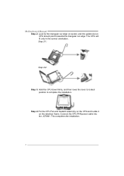
Connect the CPU FAN power cable into the JCFAN1. Step 2-1: Step 2-2: Step 3: Hold the CPU down firmly, and then lower the lever to locked position to complete the installation. Motherboard Manual Step 2: Look for the triangular cut edge on socket, and the golden dot on the retention frame. Step 4: Put the CPU Fan and heatsink assembly on the CPU and buckle it on CPU should point forwards this triangular cut edge. The CPU will fit only in the correct orientation. This completes the installation. 8
Connect the CPU FAN power cable into the JCFAN1. Step 2-1: Step 2-2: Step 3: Hold the CPU down firmly, and then lower the lever to locked position to complete the installation. Motherboard Manual Step 2: Look for the triangular cut edge on socket, and the golden dot on the retention frame. Step 4: Put the CPU Fan and heatsink assembly on the CPU and buckle it on CPU should point forwards this triangular cut edge. The CPU will fit only in the correct orientation. This completes the installation. 8
Setup Manual
Page 10
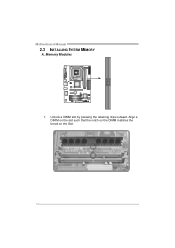
Unlock a DIMM slot by pressing the retaining clips outward. Align a DIMM on the slot such that the notch on the DIMM matches the break on the Slot. 10 Memory Modules 1. DIMM1 DIMM2 Motherboard Manual 2.3 INST ALLING SYST EM MEMORY A.
Unlock a DIMM slot by pressing the retaining clips outward. Align a DIMM on the slot such that the notch on the DIMM matches the break on the Slot. 10 Memory Modules 1. DIMM1 DIMM2 Motherboard Manual 2.3 INST ALLING SYST EM MEMORY A.
Setup Manual
Page 12
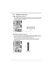
...primary ) and IDE2 (secondary ). The f irst hard drive should always be connected to four hard disk drives. Motherboard Manual 2.4 CONNECT ORS AND SLOT S FDD1: Floppy Disk Conne ctor The motherboard prov ides a standard floppy disk connector that prov ides PIO Mode 0~4, Bus Master, and Ultra DMA 33/66/...100/133 f unctionality. This connector supports the prov ided f loppy drive ribbon cable. 2 34 1 33 IDE1/IDE2: Hard Disk Conne ctors The motherboard has a 32-bit Enhanced PCI IDE Controller that supports 360K, 720K, 1.2M, 1.44M and 2.88M floppy disk ty pes. The IDE connectors can ...
...primary ) and IDE2 (secondary ). The f irst hard drive should always be connected to four hard disk drives. Motherboard Manual 2.4 CONNECT ORS AND SLOT S FDD1: Floppy Disk Conne ctor The motherboard prov ides a standard floppy disk connector that prov ides PIO Mode 0~4, Bus Master, and Ultra DMA 33/66/...100/133 f unctionality. This connector supports the prov ided f loppy drive ribbon cable. 2 34 1 33 IDE1/IDE2: Hard Disk Conne ctors The motherboard has a 32-bit Enhanced PCI IDE Controller that supports 360K, 720K, 1.2M, 1.44M and 2.88M floppy disk ty pes. The IDE connectors can ...
Setup Manual
Page 13
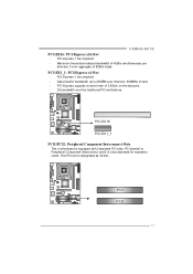
... 2.5Gb/s on the data pins. - 2X bandwidth ov er the traditional PCI architecture. P4M900-M7 FE PCI-EX16: PCI-Express x16 Slot - PCI-EX 16 PCI-EX 1_1 PCI1/PCI2: Pe riphe ral Component Inte rconne ct Slots This motherboard is designated as 32 bits. PCI-EX1_1: PCI-Express x1 Slot - PCI stands f or...
... 2.5Gb/s on the data pins. - 2X bandwidth ov er the traditional PCI architecture. P4M900-M7 FE PCI-EX16: PCI-Express x16 Slot - PCI-EX 16 PCI-EX 1_1 PCI1/PCI2: Pe riphe ral Component Inte rconne ct Slots This motherboard is designated as 32 bits. PCI-EX1_1: PCI-Express x1 Slot - PCI stands f or...
Setup Manual
Page 14
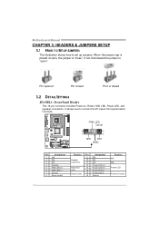
... speaker connection. Pin opened Pin closed Pin1-2 closed 3.2 DET AIL SETT INGS JPANEL1: Front Panel Heade r This 16-pin connector includes Power-on button 14 Motherboard Manual CHAPTER 3: HEADERS & JUMPERS SETUP 3.1 HOW T O SET UP JUMPERS The illustration shows how to connect the PC case's front panel switch f unctions. When the jumper...
... speaker connection. Pin opened Pin closed Pin1-2 closed 3.2 DET AIL SETT INGS JPANEL1: Front Panel Heade r This 16-pin connector includes Power-on button 14 Motherboard Manual CHAPTER 3: HEADERS & JUMPERS SETUP 3.1 HOW T O SET UP JUMPERS The illustration shows how to connect the PC case's front panel switch f unctions. When the jumper...
Setup Manual
Page 16
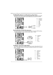
... 1 +5V (fused) 2 +5V (fused) 3 USB4 USB5 USB+ 6 USB+ 7 Ground 8 Ground 2 10 JUSB2 9 Key 10 NC 1 9 JUSB3 JSATA1/JSATA2: Se rial ATA Conne ctors The motherboard has a PCI to connect additional USB cable on the PC f ront panel, and also can be connected with internal USB devices, like USB card reader.... Motherboard Manual JUSB2/JUSB3: Heade rs for USB 2.0 Ports at Front Panel This header allows user to SATA Controller with 2 channels SATA interf ace, it satisfies...
... 1 +5V (fused) 2 +5V (fused) 3 USB4 USB5 USB+ 6 USB+ 7 Ground 8 Ground 2 10 JUSB2 9 Key 10 NC 1 9 JUSB3 JSATA1/JSATA2: Se rial ATA Conne ctors The motherboard has a PCI to connect additional USB cable on the PC f ront panel, and also can be connected with internal USB devices, like USB card reader.... Motherboard Manual JUSB2/JUSB3: Heade rs for USB 2.0 Ports at Front Panel This header allows user to SATA Controller with 2 channels SATA interf ace, it satisfies...
Setup Manual
Page 17
Wait f or f ive seconds. 4. Remov e AC power line. 2. Set the jumper to avoid damaging the motherboard. 13 Pin 1-2 Close: Normal Operation (default). 13 13 Pin 2-3 Close: Clear CMOS data. ※ Clear CMOS Proce dures: 1. Power on pin2-3, it allows user to ... data. 17 Pin Assignment 1 Left Channel Input 2 Ground 3 Ground 4 Right Channel Input 4 1 JCMO S1: Cle ar CMOS Heade r By placing the jumper on the AC. 6. P4M900-M7 FE JCDIN1: CD-RO M Audio-in Connector This connector allows user to "Pin 2-3 close ". 5.
Wait f or f ive seconds. 4. Remov e AC power line. 2. Set the jumper to avoid damaging the motherboard. 13 Pin 1-2 Close: Normal Operation (default). 13 13 Pin 2-3 Close: Clear CMOS data. ※ Clear CMOS Proce dures: 1. Power on pin2-3, it allows user to ... data. 17 Pin Assignment 1 Left Channel Input 2 Ground 3 Ground 4 Right Channel Input 4 1 JCMO S1: Cle ar CMOS Heade r By placing the jumper on the AC. 6. P4M900-M7 FE JCDIN1: CD-RO M Audio-in Connector This connector allows user to "Pin 2-3 close ". 5.
Setup Manual
Page 18
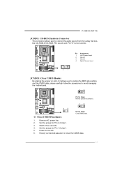
Motherboard Manual JPRNT1: Printe r Port Connector This header allows you to connector printer on the PC. 25 2 1 Pin Assignment 1 -Strobe 2 -ALF 3 Data 0 4 -Error 5 Data 1 6 -Init 7 Data 2 8 -Scltin 9 Data 3 10 Ground 11 Data 4 12 Ground 13 Data 5 Pin Assignment 14 Ground 15 Data 6 16 Ground 17 Data 7 18 Ground 19 -ACK 20 Ground 21 Busy 22 Ground 23 PE 24 Ground 25 SCLT 26 Key 18
Motherboard Manual JPRNT1: Printe r Port Connector This header allows you to connector printer on the PC. 25 2 1 Pin Assignment 1 -Strobe 2 -ALF 3 Data 0 4 -Error 5 Data 1 6 -Init 7 Data 2 8 -Scltin 9 Data 3 10 Ground 11 Data 4 12 Ground 13 Data 5 Pin Assignment 14 Ground 15 Data 6 16 Ground 17 Data 7 18 Ground 19 -ACK 20 Ground 21 Busy 22 Ground 23 PE 24 Ground 25 SCLT 26 Key 18
Setup Manual
Page 20
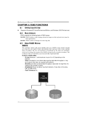
... creation of the RAID set based on the platf orm. Uses: Intended for non-critical data requiring high data throughput, or any fault tolerance. Motherboard Manual CHAPTER 4: RAID FUNCTIONS 4.1 OPERAT ION SYST EM z Supports Windows XP Home/Prof essional Edition, and Windows 2000 Prof essional. 4.2 RAID ARRAYS RAID supports the...
... creation of the RAID set based on the platf orm. Uses: Intended for non-critical data requiring high data throughput, or any fault tolerance. Motherboard Manual CHAPTER 4: RAID FUNCTIONS 4.1 OPERAT ION SYST EM z Supports Windows XP Home/Prof essional Edition, and Windows 2000 Prof essional. 4.2 RAID ARRAYS RAID supports the...
Setup Manual
Page 22
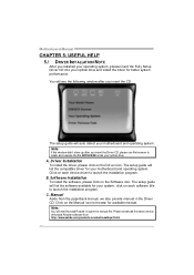
... the Software icon. Please download the latest version of Acrobat Reader soft ware from the paperback manual, we also provide manual in the Driver CD. Motherboard Manual CHAPTER 5: USEFUL HELP 5.1 DRIVER INST ALLAT ION NOT E After you installed your operating system, please insert the Fully Setup Driver CD into your optical... didn't show up after you insert the Driver CD, please use file browser to launch the installation program. The setup guide will auto detect your motherboard and operating system. Manual Aside from http://www.adobe.com/products/acrobat/readstep 2.html 22
... the Software icon. Please download the latest version of Acrobat Reader soft ware from the paperback manual, we also provide manual in the Driver CD. Motherboard Manual CHAPTER 5: USEFUL HELP 5.1 DRIVER INST ALLAT ION NOT E After you installed your operating system, please insert the Fully Setup Driver CD into your optical... didn't show up after you insert the Driver CD, please use file browser to launch the installation program. The setup guide will auto detect your motherboard and operating system. Manual Aside from http://www.adobe.com/products/acrobat/readstep 2.html 22
Setup Manual
Page 23
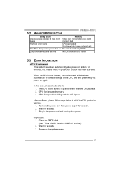
...from power supply for seconds. 3. Wait for seconds, that means the CPU protection function has been activated. CPU fan is over heated, the motherboard will shut down automatically One Short beep when system boot-up the system. Clear the CMOS data. (See "Close CMOS Header: JCMOS1" section)...siren sound CPU overheated System will shutdown automatically to relief the CPU protection function. 1. Power on again. 5.2 AWARD BIOS BEEP CODE P4M900-M7 FE Beep Sound One long beep followed by two short beeps Meaning Video card not found during POST Long beeps every other second No DRAM...
...from power supply for seconds. 3. Wait for seconds, that means the CPU protection function has been activated. CPU fan is over heated, the motherboard will shut down automatically One Short beep when system boot-up the system. Clear the CMOS data. (See "Close CMOS Header: JCMOS1" section)...siren sound CPU overheated System will shutdown automatically to relief the CPU protection function. 1. Power on again. 5.2 AWARD BIOS BEEP CODE P4M900-M7 FE Beep Sound One long beep followed by two short beeps Meaning Video card not found during POST Long beeps every other second No DRAM...
Setup Manual
Page 24
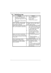
... does not turn 2. Backing up data and applications f iles. Set master/slave jumpers correctly. 2. Call the drive manuf acturers f or compatibility with other drives. 24 Motherboard Manual 5.4 TROUBLESHOOT ING Probable Solution 1. Contact technical support. 2. check the driv e type in setup. Make sure correct inf ormation is extremely important. Rev iew system...
... does not turn 2. Backing up data and applications f iles. Set master/slave jumpers correctly. 2. Call the drive manuf acturers f or compatibility with other drives. 24 Motherboard Manual 5.4 TROUBLESHOOT ING Probable Solution 1. Contact technical support. 2. check the driv e type in setup. Make sure correct inf ormation is extremely important. Rev iew system...


