
Setup Manual
Page 2
Table of Contents Chapter 1: Introduction 1 1.1 Before You Start 1 1.2 Package Checklist 1 1.3 Motherboard Features 2 1.4 Rear Panel Connectors 3 1.5 Motherboard Layout 4 Chapter 2: Hardware Installation 5 2.1 Installing Central Processing Unit (CPU 5 2.2 FAN Headers 7 2.3 Installing System Memory 8 2.4 Connectors and Slots 10 Chapter 3: Headers & Jumpers Setup 12 3.1 How to ...
Table of Contents Chapter 1: Introduction 1 1.1 Before You Start 1 1.2 Package Checklist 1 1.3 Motherboard Features 2 1.4 Rear Panel Connectors 3 1.5 Motherboard Layout 4 Chapter 2: Hardware Installation 5 2.1 Installing Central Processing Unit (CPU 5 2.2 FAN Headers 7 2.3 Installing System Memory 8 2.4 Connectors and Slots 10 Chapter 3: Headers & Jumpers Setup 12 3.1 How to ...

Setup Manual
Page 3
Before you start installing the motherboard, please make sure you follow the instructions below: „ Prepare a dry and stable working ... equipment. „ Keep the computer from anti-static bag, ground yourself properly by area or your motherboard version. 1 P31-A7 CHAPTER 1: INTRODUCTION 1.1 BEFORE YOU START Thank you take the motherboard out from dangerous area, such as heat source, humid air and water. 1.2 PACKAGE CHECKLIST HDD Cable... leave any unfastened small parts inside the case after installation. Hold the board on motherboard or the rear side of the board unless necessary.
Before you start installing the motherboard, please make sure you follow the instructions below: „ Prepare a dry and stable working ... equipment. „ Keep the computer from anti-static bag, ground yourself properly by area or your motherboard version. 1 P31-A7 CHAPTER 1: INTRODUCTION 1.1 BEFORE YOU START Thank you take the motherboard out from dangerous area, such as heat source, humid air and water. 1.2 PACKAGE CHECKLIST HDD Cable... leave any unfastened small parts inside the case after installation. Hold the board on motherboard or the rear side of the board unless necessary.

Setup Manual
Page 4
Motherboard Manual 1.3 MOTHERBOARD FEATURES SPEC LGA 775 Supports Hyper-Threading / Execute Disable Bit / Intel Core2Duo / Core2Quad / Celeron 4xx Enhanced Intel SpeedStep® / Intel Architecture-64 / CPU / Pentium D / Pentium 4 / Celeron D Extended Memory 64 Technology / Virtualization processor Technology FSB Support 533 / 800 / 1066 / 1333 MHz Chipset Intel P31 Intel ICH7 ITE 8712F Environment Control initiatives, Provides...
Motherboard Manual 1.3 MOTHERBOARD FEATURES SPEC LGA 775 Supports Hyper-Threading / Execute Disable Bit / Intel Core2Duo / Core2Quad / Celeron 4xx Enhanced Intel SpeedStep® / Intel Architecture-64 / CPU / Pentium D / Pentium 4 / Celeron D Extended Memory 64 Technology / Virtualization processor Technology FSB Support 533 / 800 / 1066 / 1333 MHz Chipset Intel P31 Intel ICH7 ITE 8712F Environment Control initiatives, Provides...

Setup Manual
Page 6
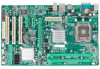
Motherboard Manual 1.5 MOTHERBOARD LAYOUT JKBMS1 LGA775 JCFAN1 JCOM1 JATXPWR1 CPU1 DDR2_A1 DDR2_B1 JUSBV1 JUSB1 JRJ45USB1 JATXPWR2 JAUDIO2 Intel P31 JAUDIOF1 JCDIN1 LAN JSPDIF_OUT1 PEX16_1 Super I/O PEX1_1 JCMOS1 PEX1_2 BAT1 BIOS PCI1 Intel ICH7 SATA1 SATA3 CODEC JPRNT1 PCI2 PCI3 FDD1 SATA2 SATA4 IDE1 JUSBV2 JUSB3 JUSB4 JSFAN1 JPANEL1 Note: ■ represents the 1st pin. 4
Motherboard Manual 1.5 MOTHERBOARD LAYOUT JKBMS1 LGA775 JCFAN1 JCOM1 JATXPWR1 CPU1 DDR2_A1 DDR2_B1 JUSBV1 JUSB1 JRJ45USB1 JATXPWR2 JAUDIO2 Intel P31 JAUDIOF1 JCDIN1 LAN JSPDIF_OUT1 PEX16_1 Super I/O PEX1_1 JCMOS1 PEX1_2 BAT1 BIOS PCI1 Intel ICH7 SATA1 SATA3 CODEC JPRNT1 PCI2 PCI3 FDD1 SATA2 SATA4 IDE1 JUSBV2 JUSB3 JUSB4 JSFAN1 JPANEL1 Note: ■ represents the 1st pin. 4

Setup Manual
Page 8
Step 2-1: Step 2-2: Step 3: Hold the CPU down firmly, and then lower the lever to locked position to complete the installation. Step 4: Put the CPU Fan and heatsink assembly on the CPU and buckle it on CPU should point forwards this triangular cut edge on socket, and the golden dot on the retention frame. Motherboard Manual Step 2: Look for the triangular cut edge. Connect the CPU FAN power cable into the JCFAN1. This completes the installation. 6 The CPU will fit only in the correct orientation.
Step 2-1: Step 2-2: Step 3: Hold the CPU down firmly, and then lower the lever to locked position to complete the installation. Step 4: Put the CPU Fan and heatsink assembly on the CPU and buckle it on CPU should point forwards this triangular cut edge on socket, and the golden dot on the retention frame. Motherboard Manual Step 2: Look for the triangular cut edge. Connect the CPU FAN power cable into the JCFAN1. This completes the installation. 6 The CPU will fit only in the correct orientation.

Setup Manual
Page 10
DDR2_A1 DDR2_B1 Motherboard Manual 2.3 INSTALLING SYSTEM MEMORY A. Align a DIMM on the slot such that the notch on the DIMM matches the break on the Slot. 2. Insert the DIMM vertically and firmly into the slot until the retaining chip snap back in place and the DIMM is properly seated. 8 Unlock a DIMM slot by pressing the retaining clips outward. Memory Modules 1.
DDR2_A1 DDR2_B1 Motherboard Manual 2.3 INSTALLING SYSTEM MEMORY A. Align a DIMM on the slot such that the notch on the DIMM matches the break on the Slot. 2. Insert the DIMM vertically and firmly into the slot until the retaining chip snap back in place and the DIMM is properly seated. 8 Unlock a DIMM slot by pressing the retaining clips outward. Memory Modules 1.

Setup Manual
Page 11
...Enabled O O (O means memory installed, X means memory not installed.) The DRAM bus width of the installed CPU. C. FSB of the installed CPU, the motherboard could support DDR2 533/667/800 modules. FSB Supporting Table According to find out the proper RAM module that fits the FSB of the memory...the following table. B. Dual Channel Memory installation To trigger the Dual Channel function of the motherboard, the memory module must be the same (x8 or x16) D. Memory Capacity P31-A7 DIMM Socket Location DDR2_A1 DDR2_B1 DDR Module 256MB/512MB/1GB/2GB 256MB/512MB/1GB/2GB Total Memory...
...Enabled O O (O means memory installed, X means memory not installed.) The DRAM bus width of the installed CPU. C. FSB of the installed CPU, the motherboard could support DDR2 533/667/800 modules. FSB Supporting Table According to find out the proper RAM module that fits the FSB of the memory...the following table. B. Dual Channel Memory installation To trigger the Dual Channel function of the motherboard, the memory module must be the same (x8 or x16) D. Memory Capacity P31-A7 DIMM Socket Location DDR2_A1 DDR2_B1 DDR Module 256MB/512MB/1GB/2GB 256MB/512MB/1GB/2GB Total Memory...

Setup Manual
Page 12
The IDE connector can connect a master and a slave drive, so you can connect up to two hard disk drives. 2 40 1 39 10 Motherboard Manual 2.4 CONNECTORS AND SLOTS FDD1: Floppy Disk Connector The motherboard provides a standard floppy disk connector that provides PIO Mode 0~4, Bus Master, and Ultra DMA 33/66/100 functionality. This connector supports the provided floppy drive ribbon cables. 2 34 1 33 IDE1: Hard Disk Connector The motherboard has a 32-bit Enhanced PCI IDE Controller that supports 360K, 720K, 1.2M, 1.44M and 2.88M floppy disk types.
The IDE connector can connect a master and a slave drive, so you can connect up to two hard disk drives. 2 40 1 39 10 Motherboard Manual 2.4 CONNECTORS AND SLOTS FDD1: Floppy Disk Connector The motherboard provides a standard floppy disk connector that provides PIO Mode 0~4, Bus Master, and Ultra DMA 33/66/100 functionality. This connector supports the provided floppy drive ribbon cables. 2 34 1 33 IDE1: Hard Disk Connector The motherboard has a 32-bit Enhanced PCI IDE Controller that supports 360K, 720K, 1.2M, 1.44M and 2.88M floppy disk types.

Setup Manual
Page 13
... PEX1_1/PEX1_2: PCI-Express x1 Slots - PCI-Express supports a raw bit-rate of 500MB/s totally. - PEX16_1 PEX1_1 PEX1_2 PCI1~PCI3: Peripheral Component Interconnect Slots This motherboard is designated as 32 bits. PCI-Express 1.0a compliant. - Maximum theoretical realized bandwidth of 250MB/s simultaneously per direction, for an aggregate of 8GB/s totally. Maximum... for Peripheral Component Interconnect, and it is a bus standard for an aggregate of 2.5GB/s on the data pins. - 2X bandwidth over the traditional PCI architecture. P31-A7 PEX16_1: PCI-Express x16 Slot -
... PEX1_1/PEX1_2: PCI-Express x1 Slots - PCI-Express supports a raw bit-rate of 500MB/s totally. - PEX16_1 PEX1_1 PEX1_2 PCI1~PCI3: Peripheral Component Interconnect Slots This motherboard is designated as 32 bits. PCI-Express 1.0a compliant. - Maximum theoretical realized bandwidth of 250MB/s simultaneously per direction, for an aggregate of 8GB/s totally. Maximum... for Peripheral Component Interconnect, and it is a bus standard for an aggregate of 2.5GB/s on the data pins. - 2X bandwidth over the traditional PCI architecture. P31-A7 PEX16_1: PCI-Express x16 Slot -

Setup Manual
Page 14
... , Reset, HDD LED, Power LED, and speaker connection. When the jumper cap is "open". PWR_LED On/Off ++ - 9 16 1 8 +- It allows user to set up jumpers. Motherboard Manual CHAPTER 3: HEADERS & JUMPERS SETUP 3.1 HOW TO SETUP JUMPERS The illustration shows how to connect the PC case's front panel switch functions. SPK RST HLED...
... , Reset, HDD LED, Power LED, and speaker connection. When the jumper cap is "open". PWR_LED On/Off ++ - 9 16 1 8 +- It allows user to set up jumpers. Motherboard Manual CHAPTER 3: HEADERS & JUMPERS SETUP 3.1 HOW TO SETUP JUMPERS The illustration shows how to connect the PC case's front panel switch functions. SPK RST HLED...

Setup Manual
Page 16
... with the PC front panel. Pin Assignment 1 1 Left Channel Input 2 Ground 3 Ground 4 4 Right Channel Input 14 This header allows only HD audio front panel connector; Motherboard Manual JUSB3/JUSB4: Headers for USB 2.0 Ports at Front Panel This header allows user to connect the audio source from the variaty devices, like USB...
... with the PC front panel. Pin Assignment 1 1 Left Channel Input 2 Ground 3 Ground 4 4 Right Channel Input 14 This header allows only HD audio front panel connector; Motherboard Manual JUSB3/JUSB4: Headers for USB 2.0 Ports at Front Panel This header allows user to connect the audio source from the variaty devices, like USB...
Setup Manual
Page 17
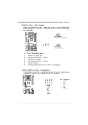
... the BIOS safe setting and the CMOS data, please carefully follow the procedures to avoid damaging the motherboard. 13 Pin 1-2 Close: Normal Operation (default). 13 13 Pin 2-3 Close: Clear CMOS data. ※ Clear CMOS Procedures: 1. P31-A7 JCMOS1: Clear CMOS Header By placing the jumper on the AC. 6. Wait for five seconds. 4. Remove...
... the BIOS safe setting and the CMOS data, please carefully follow the procedures to avoid damaging the motherboard. 13 Pin 1-2 Close: Normal Operation (default). 13 13 Pin 2-3 Close: Clear CMOS data. ※ Clear CMOS Procedures: 1. P31-A7 JCMOS1: Clear CMOS Header By placing the jumper on the AC. 6. Wait for five seconds. 4. Remove...

Setup Manual
Page 18
Motherboard Manual JSPDIF_OUT1: Digital Audio-out Connector (Optional) This connector allows user to support this function "Power-On system via USB device," "JUSBV1/ JUSBV2" jumper cap ...
Motherboard Manual JSPDIF_OUT1: Digital Audio-out Connector (Optional) This connector allows user to support this function "Power-On system via USB device," "JUSBV1/ JUSBV2" jumper cap ...
Setup Manual
Page 20
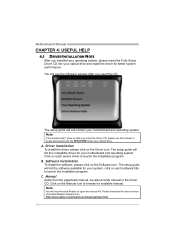
...performance. Note: If this window didn't show up after you insert the CD The setup guide will list the software available for your motherboard and operating system. B. Software Installation To install the software, please click on the Driver icon. Click on each device driver to ...launch the installation program. The setup guide will need Acrobat Reader to open the manual file. A. Motherboard Manual CHAPTER 4: USEFUL HELP 4.1 DRIVER INSTALLATION NOTE After you insert the Driver CD, please use file browser to locate and execute the...
...performance. Note: If this window didn't show up after you insert the CD The setup guide will list the software available for your motherboard and operating system. B. Software Installation To install the software, please click on the Driver icon. Click on each device driver to ...launch the installation program. The setup guide will need Acrobat Reader to open the manual file. A. Motherboard Manual CHAPTER 4: USEFUL HELP 4.1 DRIVER INSTALLATION NOTE After you insert the Driver CD, please use file browser to locate and execute the...

Setup Manual
Page 21
...is fulfilling with the CPU surface. 2. Wait for seconds. 2. Clear the CMOS data. (See "Close CMOS Header: JCMOS1" section) 2. P31-A7 4.2 AWARD BIOS BEEP CODE Beep Sound Meaning One long beep followed by two short Video card not found during POST Long beeps every other second ...automatically after power on system for seconds, that means the CPU protection function has been activated. The CPU cooler surface is over heated, the motherboard will shut down automatically One Short beep when system boot-up the system. Remove the power cord from power supply for seconds. 3. Wait for...
...is fulfilling with the CPU surface. 2. Wait for seconds. 2. Clear the CMOS data. (See "Close CMOS Header: JCMOS1" section) 2. P31-A7 4.2 AWARD BIOS BEEP CODE Beep Sound Meaning One long beep followed by two short Video card not found during POST Long beeps every other second ...automatically after power on system for seconds, that means the CPU protection function has been activated. The CPU cooler surface is over heated, the motherboard will shut down automatically One Short beep when system boot-up the system. Remove the power cord from power supply for seconds. 3. Wait for...

Setup Manual
Page 22
.... is impossible. Back up the hard drive is spinning. Screen message says "Invalid Configuration" or "CMOS Failure." Run SETUP program and select correct drive types. Motherboard Manual 4.4 TROUBLESHOOTING Probable Solution 1. System only boots from hard disk 1. on keyboard does not turn 2. System does not boot from optical drive. 1. Make sure both...
.... is impossible. Back up the hard drive is spinning. Screen message says "Invalid Configuration" or "CMOS Failure." Run SETUP program and select correct drive types. Motherboard Manual 4.4 TROUBLESHOOTING Probable Solution 1. System only boots from hard disk 1. on keyboard does not turn 2. System does not boot from optical drive. 1. Make sure both...

