

N4SLI-A9 user's manual
Page 2
Table of Contents Chapter 1: Introduction 1 1.1 Motherboard Features 1 1.2 Package Checklist 6 1.3 Layout & Components 7 Chapter 2: Hardware Installation 8 2.1 Central Processing Unit (CPU 8 2.2 Fan Headers 9 2.3 Memory Modules Installation 10 2.4 Connectors & Slots 11 Chapter 3: Headers & Jumpers Setup ...
Table of Contents Chapter 1: Introduction 1 1.1 Motherboard Features 1 1.2 Package Checklist 6 1.3 Layout & Components 7 Chapter 2: Hardware Installation 8 2.1 Central Processing Unit (CPU 8 2.2 Fan Headers 9 2.3 Memory Modules Installation 10 2.4 Connectors & Slots 11 Chapter 3: Headers & Jumpers Setup ...
N4SLI-A9 user's manual
Page 3
... IDE λ 2 on-board connectors support 4 IDE disk drives. λ Supports PIO mode 5, Block Mode and Ultra DMA 33/66/100/133 bus master mode. 1 N4SLI-A9 CHAPTER 1: INTRODUCTION 1.1 MOTHERBOARD FEATURES A.
... IDE λ 2 on-board connectors support 4 IDE disk drives. λ Supports PIO mode 5, Block Mode and Ultra DMA 33/66/100/133 bus master mode. 1 N4SLI-A9 CHAPTER 1: INTRODUCTION 1.1 MOTHERBOARD FEATURES A.
N4SLI-A9 user's manual
Page 13
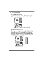
N4SLI-A9 2.4 CONNECTORS & SLOTS FDD1: Floppy Disk Connector The motherboard provides a standard floppy disk connector that provides PIO Mode 0~5, Bus Master, and Ultra DMA 33/66/100/133 functionality. This connector supports the provided floppy drive ribbon cables. 2 34 1 33 IDE1/IDE2: Hard Disk Connectors The motherboard has two 32-bit Enhanced PCI IDE Controller...
N4SLI-A9 2.4 CONNECTORS & SLOTS FDD1: Floppy Disk Connector The motherboard provides a standard floppy disk connector that provides PIO Mode 0~5, Bus Master, and Ultra DMA 33/66/100/133 functionality. This connector supports the provided floppy drive ribbon cables. 2 34 1 33 IDE1/IDE2: Hard Disk Connectors The motherboard has two 32-bit Enhanced PCI IDE Controller...

N4SLI-A9 user's manual
Page 14
...-1/PEX1-1/PEX1-2 (Normal Mode): - PCI Express 1.0a compliant. - Maximum bandwidth is up to 4GB/s per direction. Maximum bandwidth is a bus standard for expansion cards. N4SLI-A9 PCI1~PCI3: Peripheral Component Interconnect Slots This motherboard is designated as 32 bits. PCI stands for Peripheral Component Interconnect, and it is up to 2GB/s per direction.
...-1/PEX1-1/PEX1-2 (Normal Mode): - PCI Express 1.0a compliant. - Maximum bandwidth is up to 4GB/s per direction. Maximum bandwidth is a bus standard for expansion cards. N4SLI-A9 PCI1~PCI3: Peripheral Component Interconnect Slots This motherboard is designated as 32 bits. PCI stands for Peripheral Component Interconnect, and it is up to 2GB/s per direction.
N4SLI-A9 user's manual
Page 20
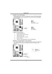
... restore the BIOS safe setting and the CMOS data, please carefully follow the procedures to avoid damaging the motherboard. 13 Pin 1-2 close: Normal Operation (Default). 13 13 Pin 2-3 close ". 5. Remove AC power line. 2. N4SLI-A9 JCMOS1: Clear CMOS Header By placing the jumper on the AC. 6. Power on pin2-3, it will record to...
... restore the BIOS safe setting and the CMOS data, please carefully follow the procedures to avoid damaging the motherboard. 13 Pin 1-2 close: Normal Operation (Default). 13 13 Pin 2-3 close ". 5. Remove AC power line. 2. N4SLI-A9 JCMOS1: Clear CMOS Header By placing the jumper on the AC. 6. Power on pin2-3, it will record to...
N4SLI-A9 user's manual
Page 21
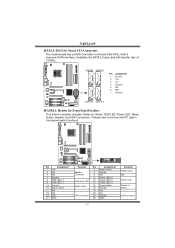
N4SLI-A9 JSATA1~JSATA4: Serial ATA Connectors The motherboard has a SATA Controller in nForce4 CK8-04 SLI with 4 channels SATA interface, it satisfies the SATA 2.0 spec and with transfer rate of 3.0Gb/s. It allows ...
N4SLI-A9 JSATA1~JSATA4: Serial ATA Connectors The motherboard has a SATA Controller in nForce4 CK8-04 SLI with 4 channels SATA interface, it satisfies the SATA 2.0 spec and with transfer rate of 3.0Gb/s. It allows ...
N4SLI-A9 user's manual
Page 22
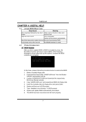
... below to DOS prompt. 7. Download the Flash Utility "AWDFLASH.exe" from Biostar website. 4. Make a bootable floppy disk. 2. Confirm motherboard model and download the respectively BIOS from the Biostar website: www.biostar.com.tw 3. Type "Awdflash xxxx.bf/sn/py/r" in DOS prompt. ...8. System will work properly. 20 System will boo-up No error found or video card memory bad High-low siren sound CPU overheated System will shut down automatically One Short beep when system boot-up to restore the BIOS: 1. N4SLI-A9...
... below to DOS prompt. 7. Download the Flash Utility "AWDFLASH.exe" from Biostar website. 4. Make a bootable floppy disk. 2. Confirm motherboard model and download the respectively BIOS from the Biostar website: www.biostar.com.tw 3. Type "Awdflash xxxx.bf/sn/py/r" in DOS prompt. ...8. System will work properly. 20 System will boo-up No error found or video card memory bad High-low siren sound CPU overheated System will shut down automatically One Short beep when system boot-up to restore the BIOS: 1. N4SLI-A9...
N4SLI-A9 user's manual
Page 23
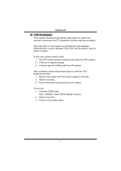
N4SLI-A9 B. Plug in the power cord and boot up the system. The CPU cooler surface is rotated normally. 3. After confirmed, please follow steps below to avoid a ...: Clear CMOS Header" section) 2. CPU Overheated If the system shutdown automatically after power on the system again. 21 CPU fan speed is over heated, the motherboard will shutdown automatically to relief the CPU protection function. 1. In this case, please double check: 1. Wait for seconds, that means the CPU protection function has...
N4SLI-A9 B. Plug in the power cord and boot up the system. The CPU cooler surface is rotated normally. 3. After confirmed, please follow steps below to avoid a ...: Clear CMOS Header" section) 2. CPU Overheated If the system shutdown automatically after power on the system again. 21 CPU fan speed is over heated, the motherboard will shutdown automatically to relief the CPU protection function. 1. In this case, please double check: 1. Wait for seconds, that means the CPU protection function has...
N4SLI-A9 user's manual
Page 25
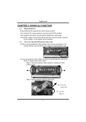
Step 2: Pull the selector card out of the slot. ○2 pull out the selector card ○1 about 45O degree lift. 23 N4SLI-A9 CHAPTER 5: NVIDIA SLI FUNCTION 5.1 REQUIREMENTS λOnly Windows XP supports SLI (Dual Video) function. λTwo identical SLI-ready graphics cards that are NVIDIA certified. &#... selector card. Step 1: Push the retention clips outward to support dual video cards. The default setting is a pre-installed SLI-NF4 selector card on the motherboard.
Step 2: Pull the selector card out of the slot. ○2 pull out the selector card ○1 about 45O degree lift. 23 N4SLI-A9 CHAPTER 5: NVIDIA SLI FUNCTION 5.1 REQUIREMENTS λOnly Windows XP supports SLI (Dual Video) function. λTwo identical SLI-ready graphics cards that are NVIDIA certified. &#... selector card. Step 1: Push the retention clips outward to support dual video cards. The default setting is a pre-installed SLI-NF4 selector card on the motherboard.
N4SLI-A9 user's manual
Page 35
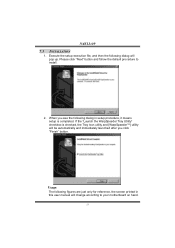
If the "Launch the WarpSpeeder Tray Utility" checkbox is completed. Please click "Next" button and follow the default procedure to your motherboard on hand. 33 N4SLI-A9 7.3 1. Usage: The following figures are just only for reference, the screen printed in setup procedure, it means setup is checked, the Tray Icon utility and [...
If the "Launch the WarpSpeeder Tray Utility" checkbox is completed. Please click "Next" button and follow the default procedure to your motherboard on hand. 33 N4SLI-A9 7.3 1. Usage: The following figures are just only for reference, the screen printed in setup procedure, it means setup is checked, the Tray Icon utility and [...
N4SLI-A9 BIOS guide
Page 16
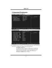
Select "Enabled" to deactivate an interface if you a submenu with the following options: OnChip IDE Channel 0/1 The motherboard chipset contains a PCI IDE interface with support for two IDE channels. Integrated Peripherals IDE Function Setup If you highlight the literal "Press Enter" next to ... the enter key, it will take you are going to install a primary and/or secondary add-in IDE interface. The Choices: Enabled (default), Disabled. 15 N4SLI-A9 5 Integrated Peripherals Figure 5. Select "Disabled" to activate the first and/or second IDE interface.
Select "Enabled" to deactivate an interface if you a submenu with the following options: OnChip IDE Channel 0/1 The motherboard chipset contains a PCI IDE interface with support for two IDE channels. Integrated Peripherals IDE Function Setup If you highlight the literal "Press Enter" next to ... the enter key, it will take you are going to install a primary and/or secondary add-in IDE interface. The Choices: Enabled (default), Disabled. 15 N4SLI-A9 5 Integrated Peripherals Figure 5. Select "Disabled" to activate the first and/or second IDE interface.

