
N4SIE-A7 user's manual
Page 2
Table of Contents Chapter 1: Introduction 1 1.1 Motherboard Features 1 1.2 Package Checklist 5 1.3 Layout and Components 6 Chapter 2: Hardware Installation 7 2.1 Installing Central Processing Unit (CPU 7 2.2 FAN Headers 9 2.3 Installing System Memory 10 2.4 Connectors and Slots 11 Chapter 3: ...
Table of Contents Chapter 1: Introduction 1 1.1 Motherboard Features 1 1.2 Package Checklist 5 1.3 Layout and Components 6 Chapter 2: Hardware Installation 7 2.1 Installing Central Processing Unit (CPU 7 2.2 FAN Headers 9 2.3 Installing System Memory 10 2.4 Connectors and Slots 11 Chapter 3: ...
N4SIE-A7 user's manual
Page 3
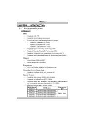
...; Maximum DRAM space is 16GB. Chipset λ North Bridge: NF4-SLI-SPP. λ South Bridge: NF4-SLI-MCP. DDR2_B2 256MB/512MB/1GB/2GB/4GB*1 1 N4SIE-A7 CHAPTER 1: INTRODUCTION 1.1 MOTHERBOARD FEATURES A. Hardware CPU λ Supports LGA 775. λ Supports Intel Pentium 4 processor. λ Front Side Bus at the following frequency ranges: 533MT/s (133MHz...
...; Maximum DRAM space is 16GB. Chipset λ North Bridge: NF4-SLI-SPP. λ South Bridge: NF4-SLI-MCP. DDR2_B2 256MB/512MB/1GB/2GB/4GB*1 1 N4SIE-A7 CHAPTER 1: INTRODUCTION 1.1 MOTHERBOARD FEATURES A. Hardware CPU λ Supports LGA 775. λ Supports Intel Pentium 4 processor. λ Front Side Bus at the following frequency ranges: 533MT/s (133MHz...
N4SIE-A7 user's manual
Page 13
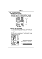
N4SIE-A7 2.4 CONNECTORS AND SLOTS FDD1: Floppy Disk Connector The motherboard provides a standard floppy disk connector that provides PIO Mode 0~5, Bus Master, and Ultra DMA 33/66/100/133 functionality. The first hard drive should always ...be connected to four hard disk drives. This connector supports the provided floppy drive ribbon cables. 34 33 2 1 IDE1/IDE2: Hard Disk Connector The motherboard has two 32-bit Enhanced PCI IDE Controller that supports 360K, 720K, 1.2M, 1.44M and 2.88M floppy disk types. It has two HDD connectors IDE1...
N4SIE-A7 2.4 CONNECTORS AND SLOTS FDD1: Floppy Disk Connector The motherboard provides a standard floppy disk connector that provides PIO Mode 0~5, Bus Master, and Ultra DMA 33/66/100/133 functionality. The first hard drive should always ...be connected to four hard disk drives. This connector supports the provided floppy drive ribbon cables. 34 33 2 1 IDE1/IDE2: Hard Disk Connector The motherboard has two 32-bit Enhanced PCI IDE Controller that supports 360K, 720K, 1.2M, 1.44M and 2.88M floppy disk types. It has two HDD connectors IDE1...
N4SIE-A7 user's manual
Page 14
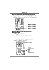
...-EX1-2: PCI-Express Slots PCI-EX16-1 (Normal Mode): - PCI Express 1.0a compliant. - PCI-EX16-1 PCI-EX1_1 PCI-EX1_2 PCI-EX16-2 12 N4SIE-A7 PCI1~PCI3: Peripheral Component Interconnect Slots This motherboard is designated as 32 bits. PCI stands for Peripheral Component Interconnect, and it is up to 2GB/s per direction. Maximum bandwidth is...
...-EX1-2: PCI-Express Slots PCI-EX16-1 (Normal Mode): - PCI Express 1.0a compliant. - PCI-EX16-1 PCI-EX1_1 PCI-EX1_2 PCI-EX16-2 12 N4SIE-A7 PCI1~PCI3: Peripheral Component Interconnect Slots This motherboard is designated as 32 bits. PCI stands for Peripheral Component Interconnect, and it is up to 2GB/s per direction. Maximum bandwidth is...
N4SIE-A7 user's manual
Page 19
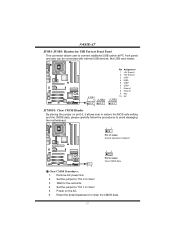
...to "Pin 1-2 close ". 3. Set the jumper to "Pin 2-3 close ". 5. Reset the desired password or clear the CMOS data. 17 N4SIE-A7 JUSB1~JUSB3: Headers for five seconds. 4. Power on pin2-3, it allows user to restore the BIOS safe setting and the CMOS data, please ... be connected with internal USB devices, like USB card reader. Wait for USB Ports at Front Panel This connector allows user to avoid damaging the motherboard. 13 Pin 1-2 close: Normal Operation (Default). 13 Pin 2-3 close: Clear CMOS data. 13 ※ Clear CMOS Procedures: 1. JUSB1 2 10 JUSB2 Pin Assignment 1 +...
...to "Pin 1-2 close ". 3. Set the jumper to "Pin 2-3 close ". 5. Reset the desired password or clear the CMOS data. 17 N4SIE-A7 JUSB1~JUSB3: Headers for five seconds. 4. Power on pin2-3, it allows user to restore the BIOS safe setting and the CMOS data, please ... be connected with internal USB devices, like USB card reader. Wait for USB Ports at Front Panel This connector allows user to avoid damaging the motherboard. 13 Pin 1-2 close: Normal Operation (Default). 13 Pin 2-3 close: Clear CMOS data. 13 ※ Clear CMOS Procedures: 1. JUSB1 2 10 JUSB2 Pin Assignment 1 +...
N4SIE-A7 user's manual
Page 20
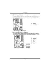
Pin Assignment 1 Case open signal 2 Ground 12 JSATA1~JSATA4: Serial ATA Connectors The motherboard has a SATA Controller in NVIDIA Crush19 with 4 channels SATA interface, it will record to monitor PC case open status. Pin Assignment 1 Ground 2 TX+ 3 TX4 Ground 5 RX6 RX+ SATA2SATA1 7 Ground 741 741 SATA4SATA3 18 If the signal has been triggered, it satisfies the SATA 2.0 spec and with transfer rate of 3.0Gb/s. N4SIE-A7 JCI1: Case Open Headers This connector allows system to the CMOS and show the message on next boot-up.
Pin Assignment 1 Case open signal 2 Ground 12 JSATA1~JSATA4: Serial ATA Connectors The motherboard has a SATA Controller in NVIDIA Crush19 with 4 channels SATA interface, it will record to monitor PC case open status. Pin Assignment 1 Ground 2 TX+ 3 TX4 Ground 5 RX6 RX+ SATA2SATA1 7 Ground 741 741 SATA4SATA3 18 If the signal has been triggered, it satisfies the SATA 2.0 spec and with transfer rate of 3.0Gb/s. N4SIE-A7 JCI1: Case Open Headers This connector allows system to the CMOS and show the message on next boot-up.
N4SIE-A7 user's manual
Page 22
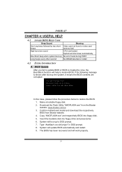
...N4SIE-A7 CHAPTER 4: USEFUL HELP 4.1 AWARD BIOS BEEP CODE Beep Sound One long beep followed by virus, the Boot-Block function will help to restore BIOS. In this Case, please follow the procedure below to restore the BIOS: 1. System will work properly. 20 Confirm motherboard model and download the respectively BIOS from the Biostar... website: www.biostar.com.tw 3. The BIOS has been recovered and will update BIOS automatically and ...
...N4SIE-A7 CHAPTER 4: USEFUL HELP 4.1 AWARD BIOS BEEP CODE Beep Sound One long beep followed by virus, the Boot-Block function will help to restore BIOS. In this Case, please follow the procedure below to restore the BIOS: 1. System will work properly. 20 Confirm motherboard model and download the respectively BIOS from the Biostar... website: www.biostar.com.tw 3. The BIOS has been recovered and will update BIOS automatically and ...
N4SIE-A7 user's manual
Page 23
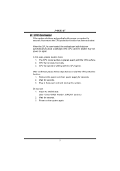
N4SIE-A7 B. When the CPU is fulfilling with the CPU surface. 2. CPU fan speed is over heated, the motherboard will shutdown automatically to relief the CPU protection function. 1. Or you can: 1. In this case, please double check: 1. Plug in the power cord and boot ...
N4SIE-A7 B. When the CPU is fulfilling with the CPU surface. 2. CPU fan speed is over heated, the motherboard will shutdown automatically to relief the CPU protection function. 1. Or you can: 1. In this case, please double check: 1. Plug in the power cord and boot ...
N4SIE-A7 user's manual
Page 25
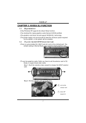
... lift. 23 Step 1: Push the retention clips outward to support dual video cards. The default setting is a pre-installed SLI-NF4T selector card on the motherboard. N4SIE-A7 CHAPTER 5: NVIDIA SLI FUNCTION 5.1 REQUIREMENTS λOnly Windows XP supports SLI (Dual Video) function. λTwo identical SLI-ready graphics cards that are NVIDIA certified...
... lift. 23 Step 1: Push the retention clips outward to support dual video cards. The default setting is a pre-installed SLI-NF4T selector card on the motherboard. N4SIE-A7 CHAPTER 5: NVIDIA SLI FUNCTION 5.1 REQUIREMENTS λOnly Windows XP supports SLI (Dual Video) function. λTwo identical SLI-ready graphics cards that are NVIDIA certified...
N4SIE-A7 user's manual
Page 34
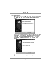
...;] utility will pop up. If the "Launch the WarpSpeeder Tray Utility" checkbox is completed. Please click "Next" button and follow the default procedure to your motherboard on hand. 32 When you click "Finish" button. Usage: The following dialog in this user manual will change according to install. 2. N4SIE-A7 7.3 1.
...;] utility will pop up. If the "Launch the WarpSpeeder Tray Utility" checkbox is completed. Please click "Next" button and follow the default procedure to your motherboard on hand. 32 When you click "Finish" button. Usage: The following dialog in this user manual will change according to install. 2. N4SIE-A7 7.3 1.
N4SIE-A7 BIOS guide
Page 18
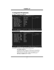
The Choices: Enabled (default), Disabled. 17 N4SIE-A7 5 Integrated Peripherals Figure 5. Select "Enabled" to the "IDE Function Setup" label and then press the enter key, it will take you a submenu with the following options: OnChip IDE Channel 0/1 The motherboard chipset contains a PCI IDE interface with support for two IDE channels. Integrated Peripherals IDE Function...
The Choices: Enabled (default), Disabled. 17 N4SIE-A7 5 Integrated Peripherals Figure 5. Select "Enabled" to the "IDE Function Setup" label and then press the enter key, it will take you a submenu with the following options: OnChip IDE Channel 0/1 The motherboard chipset contains a PCI IDE interface with support for two IDE channels. Integrated Peripherals IDE Function...

