Update Manual
Page 3
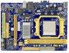
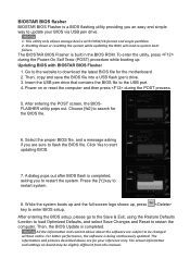
...the BIOS file. 6. While the system boots up and the full screen logo shows up . All the information and content above are for the motherboard. 2. A dialog pops out after BIOS flash is completed, asking you an easy and simple way to update your reference only. Then, the BIOS... Update is completed. BIOSTAR BIOS flasher BIOSTAR BIOS Flasher is a BIOS flashing utility providing you to restart the system. Shutting down or resetting the system while updating the BIOS ...
...the BIOS file. 6. While the system boots up and the full screen logo shows up . All the information and content above are for the motherboard. 2. A dialog pops out after BIOS flash is completed, asking you an easy and simple way to update your reference only. Then, the BIOS... Update is completed. BIOSTAR BIOS flasher BIOSTAR BIOS Flasher is a BIOS flashing utility providing you to restart the system. Shutting down or resetting the system while updating the BIOS ...
Setup Manual
Page 2
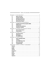
Table of Contents Chapter 1: Introduction 1 1.1 Before You Start 1 1.2 Package Checklist 1 1.3 Motherboard Features 2 1.4 Rear Panel Connectors 3 1.5 Motherboard Layout 4 Chapter 2: Hardware Installation 5 2.1 Installing Central Processing Unit (CPU 5 2.2 FAN Headers 7 2.3 Installing System Memory 8 2.4 Connectors and Slots 10 Chapter 3: Headers & Jumpers Setup 12 3.1 How to ...
Table of Contents Chapter 1: Introduction 1 1.1 Before You Start 1 1.2 Package Checklist 1 1.3 Motherboard Features 2 1.4 Rear Panel Connectors 3 1.5 Motherboard Layout 4 Chapter 2: Hardware Installation 5 2.1 Installing Central Processing Unit (CPU 5 2.2 FAN Headers 7 2.3 Installing System Memory 8 2.4 Connectors and Slots 10 Chapter 3: Headers & Jumpers Setup 12 3.1 How to ...
Setup Manual
Page 3
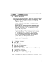
... BEFORE YOU START Thank you take the motherboard out from anti-static bag, ground yourself properly by area or your motherboard version. 1 Hold the board on the edge, do not try to remove the static charge. „ Avoid touching the components on motherboard or the rear side of the board ...unless necessary. Before you start installing the motherboard, please make sure you follow the instructions below: „ Prepare a dry and stable working environment ...
... BEFORE YOU START Thank you take the motherboard out from anti-static bag, ground yourself properly by area or your motherboard version. 1 Hold the board on the edge, do not try to remove the static charge. „ Avoid touching the components on motherboard or the rear side of the board ...unless necessary. Before you start installing the motherboard, please make sure you follow the instructions below: „ Prepare a dry and stable working environment ...
Setup Manual
Page 4
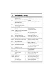
Motherboard Manual 1.3 MOTHERBOARD FEATURES SPEC Socket AM2 / AM2+ AMD 64 Architecture enables 32 and 64 bit AMD Athlon 64 / Athlon 64 FX / Athlon 64 x2 CPU computing / Sempron / ...
Motherboard Manual 1.3 MOTHERBOARD FEATURES SPEC Socket AM2 / AM2+ AMD 64 Architecture enables 32 and 64 bit AMD Athlon 64 / Athlon 64 FX / Athlon 64 x2 CPU computing / Sempron / ...
Setup Manual
Page 8
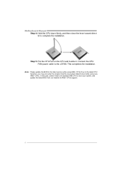
... to the JCFAN. Connect the CPU FAN power cable to boot your system, and update the latest BIOS from our website for AM2+ CPUs support. 6 Motherboard Manual Step 4: Hold the CPU down firmly, and then close the lever toward direct B to complete the installation. Step 5: Put the CPU Fan on the...
... to the JCFAN. Connect the CPU FAN power cable to boot your system, and update the latest BIOS from our website for AM2+ CPUs support. 6 Motherboard Manual Step 4: Hold the CPU down firmly, and then close the lever toward direct B to complete the installation. Step 5: Put the CPU Fan on the...

Setup Manual
Page 10
DIM MA1 DIM MB1 Motherboard Manual 2.3 INSTALLING SYSTEM MEMORY A. Unlock a DIMM slot by pressing the retaining clips outward. Align a DIMM on the slot so that the notch on the DIMM matches the break on the Slot. 2. Insert the DIMM vertically and firmly into the slot until the retaining chip snap back in place and the DIMM is properly seated. 8 Memory Modules 1.
DIM MA1 DIM MB1 Motherboard Manual 2.3 INSTALLING SYSTEM MEMORY A. Unlock a DIMM slot by pressing the retaining clips outward. Align a DIMM on the slot so that the notch on the DIMM matches the break on the Slot. 2. Insert the DIMM vertically and firmly into the slot until the retaining chip snap back in place and the DIMM is properly seated. 8 Memory Modules 1.
Setup Manual
Page 11
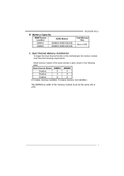
... bus width of the same density in pairs, shown in the following table. Dual Channel Memory installation To trigger the Dual Channel function of the motherboard, the memory module must meet the following requirements: Install memory module of the memory module must be the same (x8 or x16) 9 C.
... bus width of the same density in pairs, shown in the following table. Dual Channel Memory installation To trigger the Dual Channel function of the motherboard, the memory module must meet the following requirements: Install memory module of the memory module must be the same (x8 or x16) 9 C.

Setup Manual
Page 12
The IDE connector can connect a master and a slave drive, so you can connect up to two drives. 40 39 21 10 This connector supports the provided floppy drive ribbon cable. 2 34 1 33 IDE: IDE/ATAPI Connector The motherboard has a 32-bit Enhanced PCI IDE Controller that supports 360K, 720K, 1.2M, 1.44M and 2.88M floppy disk types. Motherboard Manual 2.4 CONNECTORS AND SLOTS FDD: Floppy Disk Connector The motherboard provides a standard floppy disk connector that provides PIO Mode 0~4, Bus Master, and Ultra DMA 33/66/100/133 functionality.
The IDE connector can connect a master and a slave drive, so you can connect up to two drives. 40 39 21 10 This connector supports the provided floppy drive ribbon cable. 2 34 1 33 IDE: IDE/ATAPI Connector The motherboard has a 32-bit Enhanced PCI IDE Controller that supports 360K, 720K, 1.2M, 1.44M and 2.88M floppy disk types. Motherboard Manual 2.4 CONNECTORS AND SLOTS FDD: Floppy Disk Connector The motherboard provides a standard floppy disk connector that provides PIO Mode 0~4, Bus Master, and Ultra DMA 33/66/100/133 functionality.
Setup Manual
Page 13
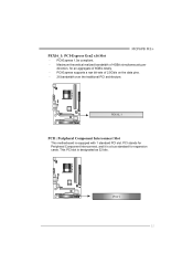
PCI-Express 1.0a compliant. - PCI stands for Peripheral Component Interconnect, and it is a bus standard for an aggregate of 8GB/s totally. - PCI-Express supports a raw bit-rate of 4GB/s simultaneously per direction, for expansion cards. PEX16_1 PCI1: Peripheral Component Interconnect Slot This motherboard is designated as 32 bits. PCI1 11 This PCI slot is equipped with 1 standard PCI slot. Maximum theoretical realized bandwidth of 2.5Gb/s on the data pins. - 2X bandwidth over the traditional PCI architecture. MCP6PB M2+ PEX16_1: PCI-Express Gen2 x16 Slot -
PCI-Express 1.0a compliant. - PCI stands for Peripheral Component Interconnect, and it is a bus standard for an aggregate of 8GB/s totally. - PCI-Express supports a raw bit-rate of 4GB/s simultaneously per direction, for expansion cards. PEX16_1 PCI1: Peripheral Component Interconnect Slot This motherboard is designated as 32 bits. PCI1 11 This PCI slot is equipped with 1 standard PCI slot. Maximum theoretical realized bandwidth of 2.5Gb/s on the data pins. - 2X bandwidth over the traditional PCI architecture. MCP6PB M2+ PEX16_1: PCI-Express Gen2 x16 Slot -
Setup Manual
Page 14
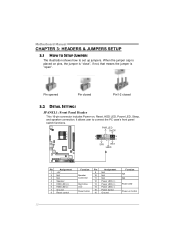
... 16 Assignment N/A N/A N/A Power LED (+) Power LED (+) Power LED (-) Power button Ground Function N/A N/A Power LED Power-on , Reset, HDD LED, Power LED, Sleep, and speaker connection. Motherboard Manual CHAPTER 3: HEADERS & JUMPERS SETUP 3.1 HOW TO SETUP JUMPERS The illustration shows how to connect the PC case's front panel switch functions. Pin opened Pin...
... 16 Assignment N/A N/A N/A Power LED (+) Power LED (+) Power LED (-) Power button Ground Function N/A N/A Power LED Power-on , Reset, HDD LED, Power LED, Sleep, and speaker connection. Motherboard Manual CHAPTER 3: HEADERS & JUMPERS SETUP 3.1 HOW TO SETUP JUMPERS The illustration shows how to connect the PC case's front panel switch functions. Pin opened Pin...
Setup Manual
Page 16
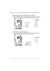
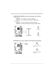
... a PCI to connect additional USB cable on the PC front panel, and also can be connected with transfer rate of 3.0Gb/s. Motherboard Manual JUSB2/JUSB3: Headers for USB 2.0 Ports at Front Panel These headers allow user to SATA Controller with 2 channels SATA interface, it satisfies the SATA 2.0 ...
... a PCI to connect additional USB cable on the PC front panel, and also can be connected with transfer rate of 3.0Gb/s. Motherboard Manual JUSB2/JUSB3: Headers for USB 2.0 Ports at Front Panel These headers allow user to SATA Controller with 2 channels SATA interface, it satisfies the SATA 2.0 ...
Setup Manual
Page 17
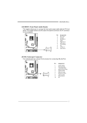
... in 2 Ground 3 Mic Right in 4 GPIO 5 Right line in 6 Jack Sense 7 Front Sense 8 Key 9 Left line in 10 Jack Sense 1 9 JCOM: Serial port Connector The motherboard has a Serial Port Connector for connecting RS-232 Port. 2 10 1 9 Pin Assignment 1 Carrier detect 2 Received data 3 Transmitted data 4 Data terminal ready 5 Signal ground 6 Data set...
... in 2 Ground 3 Mic Right in 4 GPIO 5 Right line in 6 Jack Sense 7 Front Sense 8 Key 9 Left line in 10 Jack Sense 1 9 JCOM: Serial port Connector The motherboard has a Serial Port Connector for connecting RS-232 Port. 2 10 1 9 Pin Assignment 1 Carrier detect 2 Received data 3 Transmitted data 4 Data terminal ready 5 Signal ground 6 Data set...
Setup Manual
Page 18
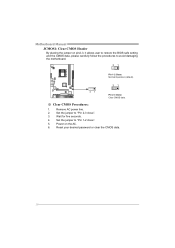
Remove AC power line. 2. Power on pin2-3, it allows user to restore the BIOS safe setting and the CMOS data, please carefully follow the procedures to avoid damaging the motherboard. 31 Pin 1-2 Close: Normal Operation (default). 31 31 Pin 2-3 Close: Clear CMOS data. ※ Clear CMOS Procedures: 1. Reset your desired password or clear the CMOS data. 16 Set the jumper to "Pin 1-2 close ". 3. Wait for five seconds. 4. Set the jumper to "Pin 2-3 close ". 5. Motherboard Manual JCMOS1: Clear CMOS Header By placing the jumper on the AC. 6.
Remove AC power line. 2. Power on pin2-3, it allows user to restore the BIOS safe setting and the CMOS data, please carefully follow the procedures to avoid damaging the motherboard. 31 Pin 1-2 Close: Normal Operation (default). 31 31 Pin 2-3 Close: Clear CMOS data. ※ Clear CMOS Procedures: 1. Reset your desired password or clear the CMOS data. 16 Set the jumper to "Pin 1-2 close ". 3. Wait for five seconds. 4. Set the jumper to "Pin 2-3 close ". 5. Motherboard Manual JCMOS1: Clear CMOS Header By placing the jumper on the AC. 6.
Setup Manual
Page 20
JUSBPWR1 1 3 3 1 JUSBPWR2 1 3 Pin 1-2 close 1 3 Pin 2-3 close JKB_PWR: Power Source Header for PS/2 Keyboard and Mouse 1 3 1 3 Pin 1-2 close +5V for PS/2 keyboard and mouse. 1 3 Pin 2-3 close +5V STB for USB ports at front panel (JUSB2/JUSB3). Motherboard Manual JUSBPWR1/JUSBPWR2: Power Source Headers for USB Ports Pin 1-2 Close: JUSBPWR1: +5V for USB ports at JUSB1/JUSBLAN1. Pin 2-3 Close: JUSBPWR1: +5V STB for USB ports at front panel (JUSB2/JUSB3). JUSBPWR2: +5V STB for USB ports at JUSB1/JUSBLAN1. JUSBPWR2: +5V for PS/2 keyboard and mouse. 18
JUSBPWR1 1 3 3 1 JUSBPWR2 1 3 Pin 1-2 close 1 3 Pin 2-3 close JKB_PWR: Power Source Header for PS/2 Keyboard and Mouse 1 3 1 3 Pin 1-2 close +5V for PS/2 keyboard and mouse. 1 3 Pin 2-3 close +5V STB for USB ports at front panel (JUSB2/JUSB3). Motherboard Manual JUSBPWR1/JUSBPWR2: Power Source Headers for USB Ports Pin 1-2 Close: JUSBPWR1: +5V for USB ports at JUSB1/JUSBLAN1. Pin 2-3 Close: JUSBPWR1: +5V STB for USB ports at front panel (JUSB2/JUSB3). JUSBPWR2: +5V STB for USB ports at JUSB1/JUSBLAN1. JUSBPWR2: +5V for PS/2 keyboard and mouse. 18

Setup Manual
Page 22
RAID techniques can reside on the same disk or on a second redundant drive in a RAID 1 array system. Motherboard Manual RAID 1: Every read and write is actually carried out in parallel across 2 disk drives in the array. Block 1 Block 2 Block 3 20 Block 1 Block 2 Block 3 ...
RAID techniques can reside on the same disk or on a second redundant drive in a RAID 1 array system. Motherboard Manual RAID 1: Every read and write is actually carried out in parallel across 2 disk drives in the array. Block 1 Block 2 Block 3 20 Block 1 Block 2 Block 3 ...
Setup Manual
Page 23
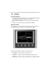
... you insert the Driver CD, please use file browser to browse for better system performance. The setup guide will list the software available for your motherboard and operating system. Note: You will auto detect your...
... you insert the Driver CD, please use file browser to browse for better system performance. The setup guide will list the software available for your motherboard and operating system. Note: You will auto detect your...
Setup Manual
Page 24
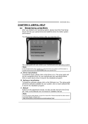
.... Transform:Transform the picture for BIOS and preview the result. 3. Select Software Installation, and then click on -screen instructions to complete the update. 22 Motherboard Manual 5.2 SOFTWARE Installing Software 1. The drivers installation program would appear if the Autorun function has been enabled. 2. Please follow the following instructions to customize your...
.... Transform:Transform the picture for BIOS and preview the result. 3. Select Software Installation, and then click on -screen instructions to complete the update. 22 Motherboard Manual 5.2 SOFTWARE Installing Software 1. The drivers installation program would appear if the Autorun function has been enabled. 2. Please follow the following instructions to customize your...
Setup Manual
Page 25
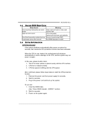
The CPU cooler surface is over heated, the motherboard will shut down automatically One Short beep when system boot-up the system. Plug in the power cord and boot up No error found during ...
The CPU cooler surface is over heated, the motherboard will shut down automatically One Short beep when system boot-up the system. Plug in the power cord and boot up No error found during ...
Setup Manual
Page 26
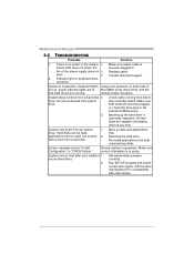
... ends of are on keyboard does not shine. Back up the hard drive is no power in . Re-install applications and data using backup disks. Motherboard Manual 5.5 TROUBLESHOOTING Probable Solution 1. There is extremely important. Make sure power cable is inoperative. the securely plugged in the system. 1. Replace cable. Contact technical support...
... ends of are on keyboard does not shine. Back up the hard drive is no power in . Re-install applications and data using backup disks. Motherboard Manual 5.5 TROUBLESHOOTING Probable Solution 1. There is extremely important. Make sure power cable is inoperative. the securely plugged in the system. 1. Replace cable. Contact technical support...

Setup Manual
Page 44
Motherboard Manual JAPANESE 仕様 Socket AM2 / AM2+ AMD 64 32ビットと64 AMD Athlon 64 / Athlon 64 FX / Althlon 64 能で&#...
Motherboard Manual JAPANESE 仕様 Socket AM2 / AM2+ AMD 64 32ビットと64 AMD Athlon 64 / Athlon 64 FX / Althlon 64 能で&#...

