

M6VCF user's manual
Page 14
CD Audio-IN connector (J7,J8) O. Frequency Selection (JP1) H. Front Panel connector(PANEL1) R. Front USB (USB2) S. ATX Power connector (POWER1) J. CPU Fan connector (J6) K. System Fan connector (J5) NOTES: After version 1.0, the ATX POWER (POWER1) will be removed just beside the KB/MS (CN1) & USB (USB1) ...
CD Audio-IN connector (J7,J8) O. Frequency Selection (JP1) H. Front Panel connector(PANEL1) R. Front USB (USB2) S. ATX Power connector (POWER1) J. CPU Fan connector (J6) K. System Fan connector (J5) NOTES: After version 1.0, the ATX POWER (POWER1) will be removed just beside the KB/MS (CN1) & USB (USB1) ...

M6VCF user's manual
Page 27
Chapter 1 Motherboard Description 1.6 CPU Installation 1.6.1 CPU Installation Procedure : Socket 370
Chapter 1 Motherboard Description 1.6 CPU Installation 1.6.1 CPU Installation Procedure : Socket 370

M6VCF user's manual
Page 28
Chapter 1 Motherboard Description 1.6.2 CPU Frequency Selection : JP1 JP1 FREQ. 66MHz 100MHz 133MHz 1 2 3 4 5 6 OPEN OPEN OPEN OPEN OPEN OPEN CLOSE CLOSE CLOSE CLOSE OPEN CLOSE OPEN CLOSE OPEN OPEN CLOSE OPEN NOTES: After version 1.0, the ATX POWER (POWER1) will be removed just beside the KB/MS (CN1) & USB (USB1) port. ( in vertical position)
Chapter 1 Motherboard Description 1.6.2 CPU Frequency Selection : JP1 JP1 FREQ. 66MHz 100MHz 133MHz 1 2 3 4 5 6 OPEN OPEN OPEN OPEN OPEN OPEN CLOSE CLOSE CLOSE CLOSE OPEN CLOSE OPEN CLOSE OPEN OPEN CLOSE OPEN NOTES: After version 1.0, the ATX POWER (POWER1) will be removed just beside the KB/MS (CN1) & USB (USB1) port. ( in vertical position)

M6VCF user's manual
Page 29
Chapter 1 Motherboard Description 1.6.3 CPU Ratio Selection : JFREQ1 JFREQ1 RATIO x 2.0 x 2.5 x 3.0 x 3.5 x 4.0 x 4.5 x 5.0 x 5.5 x 6.0 x 6.5 x 7.0 x 7.5 x 8.0 1 CLOSE CLOSE CLOSE CLOSE OPEN OPEN OPEN OPEN CLOSE CLOSE CLOSE CLOSE OPEN 2 CLOSE CLOSE OPEN OPEN CLOSE CLOSE OPEN OPEN CLOSE CLOSE OPEN OPEN CLOSE 3 CLOSE OPEN CLOSE OPEN CLOSE OPEN CLOSE OPEN CLOSE OPEN CLOSE OPEN CLOSE 4 CLOSE CLOSE CLOSE CLOSE CLOSE CLOSE CLOSE CLOSE OPEN OPEN OPEN OPEN OPEN
Chapter 1 Motherboard Description 1.6.3 CPU Ratio Selection : JFREQ1 JFREQ1 RATIO x 2.0 x 2.5 x 3.0 x 3.5 x 4.0 x 4.5 x 5.0 x 5.5 x 6.0 x 6.5 x 7.0 x 7.5 x 8.0 1 CLOSE CLOSE CLOSE CLOSE OPEN OPEN OPEN OPEN CLOSE CLOSE CLOSE CLOSE OPEN 2 CLOSE CLOSE OPEN OPEN CLOSE CLOSE OPEN OPEN CLOSE CLOSE OPEN OPEN CLOSE 3 CLOSE OPEN CLOSE OPEN CLOSE OPEN CLOSE OPEN CLOSE OPEN CLOSE OPEN CLOSE 4 CLOSE CLOSE CLOSE CLOSE CLOSE CLOSE CLOSE CLOSE OPEN OPEN OPEN OPEN OPEN
M6VCF user's manual
Page 31
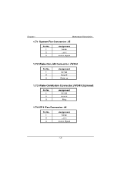
Chapter 1 Motherboard Description 1.7.1 System Fan Connector: J5 Pin No. 1 2 3 Assignment Sense +12 V Control Signal 1.7.2 Wake-On-LAN Connector: JWOL1 Pin No. 1 2 3 Assignment 5V_SB Ground Wake-up 1.7.3 Wake-On-Modem Connector:JWOM1(Optional) Pin No. 1 2 3 Assignment 5V_SB Ground Ring 1.7.4 CPU Fan Connector: J6 Pin No. 1 2 3 Assignment Sense +12 V Control Signal
Chapter 1 Motherboard Description 1.7.1 System Fan Connector: J5 Pin No. 1 2 3 Assignment Sense +12 V Control Signal 1.7.2 Wake-On-LAN Connector: JWOL1 Pin No. 1 2 3 Assignment 5V_SB Ground Wake-up 1.7.3 Wake-On-Modem Connector:JWOM1(Optional) Pin No. 1 2 3 Assignment 5V_SB Ground Ring 1.7.4 CPU Fan Connector: J6 Pin No. 1 2 3 Assignment Sense +12 V Control Signal

M6VCF user's manual
Page 45
... someone attempt to choose the VIRUS warning feature for IDE Hard disk boot sector proctection. Chapter2 2.3 Advanced BIOS Features " BIOS Setup Virus Warning CPU Internal Cache External Cache CPU L2 Cache ECC Checking Processor Number Feature Quick Power On Self Test First Boot Device Second Boot Device Third Boot Device Boot Other...
... someone attempt to choose the VIRUS warning feature for IDE Hard disk boot sector proctection. Chapter2 2.3 Advanced BIOS Features " BIOS Setup Virus Warning CPU Internal Cache External Cache CPU L2 Cache ECC Checking Processor Number Feature Quick Power On Self Test First Boot Device Second Boot Device Third Boot Device Boot Other...

M6VCF user's manual
Page 66
Chapter2 2.8 PC Health Status " BIOS Setup Show H/W Monitor in POST 3sec Current CPU FAN Speed RPM Item Help Current System FAN Speed RPM Menu Level Vcore V +2.5V V +3.3V V +5.0V V +12.0V V : Move Enter :Select +/-/PU/PD :Value F10 :Save ESC :Exit F1 :General Help F5 :Previous Values F6 :Fail-Safe Defaults F7 : Optimized Defaults
Chapter2 2.8 PC Health Status " BIOS Setup Show H/W Monitor in POST 3sec Current CPU FAN Speed RPM Item Help Current System FAN Speed RPM Menu Level Vcore V +2.5V V +3.3V V +5.0V V +12.0V V : Move Enter :Select +/-/PU/PD :Value F10 :Save ESC :Exit F1 :General Help F5 :Previous Values F6 :Fail-Safe Defaults F7 : Optimized Defaults


